EP4342828A2 - Système isolant pour remplir un récipient avec un liquide, station de transfert pour transférer un récipient et procédé associé - Google Patents
Système isolant pour remplir un récipient avec un liquide, station de transfert pour transférer un récipient et procédé associé Download PDFInfo
- Publication number
- EP4342828A2 EP4342828A2 EP24155999.6A EP24155999A EP4342828A2 EP 4342828 A2 EP4342828 A2 EP 4342828A2 EP 24155999 A EP24155999 A EP 24155999A EP 4342828 A2 EP4342828 A2 EP 4342828A2
- Authority
- EP
- European Patent Office
- Prior art keywords
- container
- module
- filling
- station
- transfer
- Prior art date
- Legal status (The legal status is an assumption and is not a legal conclusion. Google has not performed a legal analysis and makes no representation as to the accuracy of the status listed.)
- Pending
Links
Images









Classifications
-
- B—PERFORMING OPERATIONS; TRANSPORTING
- B65—CONVEYING; PACKING; STORING; HANDLING THIN OR FILAMENTARY MATERIAL
- B65B—MACHINES, APPARATUS OR DEVICES FOR, OR METHODS OF, PACKAGING ARTICLES OR MATERIALS; UNPACKING
- B65B1/00—Packaging fluent solid material, e.g. powders, granular or loose fibrous material, loose masses of small articles, in individual containers or receptacles, e.g. bags, sacks, boxes, cartons, cans, or jars
- B65B1/30—Devices or methods for controlling or determining the quantity or quality or the material fed or filled
- B65B1/46—Check-weighing of filled containers or receptacles
-
- B—PERFORMING OPERATIONS; TRANSPORTING
- B65—CONVEYING; PACKING; STORING; HANDLING THIN OR FILAMENTARY MATERIAL
- B65B—MACHINES, APPARATUS OR DEVICES FOR, OR METHODS OF, PACKAGING ARTICLES OR MATERIALS; UNPACKING
- B65B3/00—Packaging plastic material, semiliquids, liquids or mixed solids and liquids, in individual containers or receptacles, e.g. bags, sacks, boxes, cartons, cans, or jars
- B65B3/003—Filling medical containers such as ampoules, vials, syringes or the like
- B65B3/006—Related operations, e.g. scoring ampoules
-
- B—PERFORMING OPERATIONS; TRANSPORTING
- B25—HAND TOOLS; PORTABLE POWER-DRIVEN TOOLS; MANIPULATORS
- B25J—MANIPULATORS; CHAMBERS PROVIDED WITH MANIPULATION DEVICES
- B25J21/00—Chambers provided with manipulation devices
-
- B—PERFORMING OPERATIONS; TRANSPORTING
- B25—HAND TOOLS; PORTABLE POWER-DRIVEN TOOLS; MANIPULATORS
- B25J—MANIPULATORS; CHAMBERS PROVIDED WITH MANIPULATION DEVICES
- B25J21/00—Chambers provided with manipulation devices
- B25J21/005—Clean rooms
-
- B—PERFORMING OPERATIONS; TRANSPORTING
- B25—HAND TOOLS; PORTABLE POWER-DRIVEN TOOLS; MANIPULATORS
- B25J—MANIPULATORS; CHAMBERS PROVIDED WITH MANIPULATION DEVICES
- B25J9/00—Program-controlled manipulators
- B25J9/0084—Program-controlled manipulators comprising a plurality of manipulators
-
- B—PERFORMING OPERATIONS; TRANSPORTING
- B65—CONVEYING; PACKING; STORING; HANDLING THIN OR FILAMENTARY MATERIAL
- B65B—MACHINES, APPARATUS OR DEVICES FOR, OR METHODS OF, PACKAGING ARTICLES OR MATERIALS; UNPACKING
- B65B3/00—Packaging plastic material, semiliquids, liquids or mixed solids and liquids, in individual containers or receptacles, e.g. bags, sacks, boxes, cartons, cans, or jars
- B65B3/003—Filling medical containers such as ampoules, vials, syringes or the like
-
- B—PERFORMING OPERATIONS; TRANSPORTING
- B65—CONVEYING; PACKING; STORING; HANDLING THIN OR FILAMENTARY MATERIAL
- B65B—MACHINES, APPARATUS OR DEVICES FOR, OR METHODS OF, PACKAGING ARTICLES OR MATERIALS; UNPACKING
- B65B31/00—Packaging articles or materials under special atmospheric or gaseous conditions; Adding propellants to aerosol containers
- B65B31/02—Filling, closing, or filling and closing, containers or wrappers in chambers maintained under vacuum or superatmospheric pressure or containing a special atmosphere, e.g. of inert gas
- B65B31/025—Filling, closing, or filling and closing, containers or wrappers in chambers maintained under vacuum or superatmospheric pressure or containing a special atmosphere, e.g. of inert gas specially adapted for rigid or semi-rigid containers
- B65B31/027—Filling, closing, or filling and closing, containers or wrappers in chambers maintained under vacuum or superatmospheric pressure or containing a special atmosphere, e.g. of inert gas specially adapted for rigid or semi-rigid containers closed by a stopper
-
- B—PERFORMING OPERATIONS; TRANSPORTING
- B65—CONVEYING; PACKING; STORING; HANDLING THIN OR FILAMENTARY MATERIAL
- B65B—MACHINES, APPARATUS OR DEVICES FOR, OR METHODS OF, PACKAGING ARTICLES OR MATERIALS; UNPACKING
- B65B55/00—Preserving, protecting or purifying packages or package contents in association with packaging
- B65B55/02—Sterilising, e.g. of complete packages
- B65B55/027—Packaging in aseptic chambers
-
- B—PERFORMING OPERATIONS; TRANSPORTING
- B65—CONVEYING; PACKING; STORING; HANDLING THIN OR FILAMENTARY MATERIAL
- B65B—MACHINES, APPARATUS OR DEVICES FOR, OR METHODS OF, PACKAGING ARTICLES OR MATERIALS; UNPACKING
- B65B55/00—Preserving, protecting or purifying packages or package contents in association with packaging
- B65B55/02—Sterilising, e.g. of complete packages
- B65B55/12—Sterilising contents prior to, or during, packaging
- B65B55/18—Sterilising contents prior to, or during, packaging by liquids or gases
-
- B—PERFORMING OPERATIONS; TRANSPORTING
- B65—CONVEYING; PACKING; STORING; HANDLING THIN OR FILAMENTARY MATERIAL
- B65B—MACHINES, APPARATUS OR DEVICES FOR, OR METHODS OF, PACKAGING ARTICLES OR MATERIALS; UNPACKING
- B65B63/00—Auxiliary devices, not otherwise provided for, for operating on articles or materials to be packaged
- B65B63/08—Auxiliary devices, not otherwise provided for, for operating on articles or materials to be packaged for heating or cooling articles or materials to facilitate packaging
-
- B—PERFORMING OPERATIONS; TRANSPORTING
- B65—CONVEYING; PACKING; STORING; HANDLING THIN OR FILAMENTARY MATERIAL
- B65B—MACHINES, APPARATUS OR DEVICES FOR, OR METHODS OF, PACKAGING ARTICLES OR MATERIALS; UNPACKING
- B65B7/00—Closing containers or receptacles after filling
- B65B7/16—Closing semi-rigid or rigid containers or receptacles not deformed by, or not taking-up shape of, contents, e.g. boxes or cartons
- B65B7/161—Sealing filled ampoules
-
- B—PERFORMING OPERATIONS; TRANSPORTING
- B65—CONVEYING; PACKING; STORING; HANDLING THIN OR FILAMENTARY MATERIAL
- B65B—MACHINES, APPARATUS OR DEVICES FOR, OR METHODS OF, PACKAGING ARTICLES OR MATERIALS; UNPACKING
- B65B7/00—Closing containers or receptacles after filling
- B65B7/16—Closing semi-rigid or rigid containers or receptacles not deformed by, or not taking-up shape of, contents, e.g. boxes or cartons
- B65B7/168—Closing semi-rigid or rigid containers or receptacles not deformed by, or not taking-up shape of, contents, e.g. boxes or cartons by applying and securing double closures
-
- B—PERFORMING OPERATIONS; TRANSPORTING
- B65—CONVEYING; PACKING; STORING; HANDLING THIN OR FILAMENTARY MATERIAL
- B65B—MACHINES, APPARATUS OR DEVICES FOR, OR METHODS OF, PACKAGING ARTICLES OR MATERIALS; UNPACKING
- B65B7/00—Closing containers or receptacles after filling
- B65B7/16—Closing semi-rigid or rigid containers or receptacles not deformed by, or not taking-up shape of, contents, e.g. boxes or cartons
- B65B7/28—Closing semi-rigid or rigid containers or receptacles not deformed by, or not taking-up shape of, contents, e.g. boxes or cartons by applying separate preformed closures, e.g. lids, covers
- B65B7/2821—Closing semi-rigid or rigid containers or receptacles not deformed by, or not taking-up shape of, contents, e.g. boxes or cartons by applying separate preformed closures, e.g. lids, covers applying plugs or threadless stoppers
-
- B—PERFORMING OPERATIONS; TRANSPORTING
- B65—CONVEYING; PACKING; STORING; HANDLING THIN OR FILAMENTARY MATERIAL
- B65B—MACHINES, APPARATUS OR DEVICES FOR, OR METHODS OF, PACKAGING ARTICLES OR MATERIALS; UNPACKING
- B65B7/00—Closing containers or receptacles after filling
- B65B7/16—Closing semi-rigid or rigid containers or receptacles not deformed by, or not taking-up shape of, contents, e.g. boxes or cartons
- B65B7/28—Closing semi-rigid or rigid containers or receptacles not deformed by, or not taking-up shape of, contents, e.g. boxes or cartons by applying separate preformed closures, e.g. lids, covers
- B65B7/2842—Securing closures on containers
- B65B7/285—Securing closures on containers by deformation of the closure
Definitions
- the present invention relates to modular isolator systems and methods for filling a container with a liquid.
- the present invention further relates to a transfer station and a method for transferring a container between a first module and a second module.
- the present invention is primarily concerned with aseptic isolators which have a filling area for fluidly filling objects (eg vials, cartridges, bottles, syringes and/or the like), for example using filling needles.
- the term “isolator” is generally understood to mean a closed space that is hermetically and gas-tight from the surrounding work space.
- a defined atmosphere can be created within an isolator for processing sensitive or dangerous products.
- ventilation technology can be provided, for example, by means of which the defined atmosphere is created.
- isolators are commonly used in biopharmaceutical process technology, for example as part of a filling system with several process and processing stations, in order to create a highly pure or sterile, i.e. germ-free, environment and to prevent contamination by germs, in particular bacteria, viruses, pathogens and/or or the like.
- the transfer of the objects between the individual processing stations as well as the handling of the objects at the individual processing stations can, for example, be carried out manually by an operator using gloves.
- the glove openings can also be used to manage germ monitoring during production or possibly to troubleshoot problems.
- this “manual” handling using gloves is extremely time-consuming.
- glove bushings which in practice are made of rubber or plastic, especially butyl, can be damaged when gripping the objects to be handled. Glove openings therefore also represent an increased risk of contamination and/or safety as a result of leaks. The non-use and, in the best case, omission of these glove openings thus eliminates the risk of contamination that they pose
- handling devices such as robots, are used within the isolator to transfer the objects to be filled within the isolator between the individual processing stations and to handle the objects at the individual processing stations.
- the publication shows WO 2016/198391 A1 a method for filling and closing bottles, cartridges, syringes and the like, the bottles, cartridges, syringes and the like being generally referred to as containers, such containers being individually accommodated in respective seats of a first nest, which in turn is contained in a first transport tray is.
- the method consists of feeding the containers, which are individually accommodated in respective seats of the first nest, which in turn is associated with the first transport tub; Removing at least one individual container from the first nest and transferring it at least one container to a filling station to fill it with a substance; transferring the at least one filled container to a stopper placement station to place a stopper on the container; transferring the at least one filled container to a crimping station, passing the container through a partition; Closing the at least one container at the crimping station; Inserting the at least one closed container into a respective seat of a second nest.
- the filling station and the stopper setting station are arranged in a filling module.
- the flanging station is arranged in a flanging module.
- the partition is arranged between the filling module and the flanging module.
- the filling module and the flanging module each have a handling device by means of which the containers in the respective module are handled.
- the isolator system may be a system disposed within an isolator.
- the individual modules of the system can be arranged within the isolator.
- the isolator system can also be an isolator in which the individual modules of the system are arranged.
- the container is preferably a pharmaceutical container, for example a syringe, a vial, a bottle, a cylinder ampoule or the like.
- the container is preferably cylindrical. This means that the container is circular cylindrical in cross section.
- the liquid is preferably a pharmaceutical, cosmetic or toxic liquid.
- the filling station has means for filling the container.
- the filling station can, for example, have one or more filling needles for dispensing the liquid into a container.
- the filling station can also have a metering device by means of which the amount of liquid to be dispensed can be metered.
- the filling station can be connected to a liquid reservoir, in particular a tank, via one or more hoses.
- the metering device can be arranged in a fluid path between the liquid reservoir and the filling needle.
- the liquid reservoir can be arranged inside or outside the filling module.
- the filling station can be designed such that several, in particular two, containers can be filled at the same time.
- the filling station can, for example, have several, in particular two, filling needles.
- the plug setting station has means for placing a plug.
- the plug-setting station can, for example, have a support structure and a plug-setting device that can be moved by means of the support structure.
- the stopper setting device is designed to insert a stopper into the opening of the container.
- the stopper setting station can also have a feed through which the stoppers are fed to the stopper setting device.
- the plug setting station can be connected to a plug reservoir in which a plurality of plugs are stored.
- the plug reservoir can have a separating device in which the plugs are separated before they are fed separately via the feed of the plug setting device. Alternatively, the feed can be carried out by providing the plugs loosely on a plate.
- the position of the plugs can be recognized via a sensor device, for example a camera.
- the stopper setting device can have a robot which, based on the detected position, picks up a stopper and feeds it to the stopper setting device or places it directly on the container. Furthermore, the stopper setting station can be designed in such a way that a stopper can be placed on several, in particular two, containers at the same time.
- Each handling device has means for handling the container.
- each handling device can have a robot with an end effector.
- the robot can, for example, have a, preferably multi-axis, support structure, at the end of which the end effector is attached.
- the end effector can be moved within the filling module using the support structure.
- the end effector may be configured to handle the container.
- the end effector can have a gripping tool by means of which the end effector can grip the container.
- transferring the container it is meant that the container is moved from a first location, for example the filling station, to a second location, for example the stopper setting station.
- a handling device can pick up or grab the container at the first location, move it to the second location and release it again at the second location.
- each handling device can be designed such that it can handle several, in particular two, containers at the same time.
- each handling device can have, for example, an end effector with several, in particular two, gripping tools.
- the control device is set up to control one or more, in particular all, modules of the isolator system.
- the control device can send control commands to the handling devices and stations of the respective module of the isolator system in order to carry out the respective control steps of the method.
- the control device can send control commands to the filling station to fill the container.
- the control device can send control commands to one or more handling devices in order to transfer the container.
- the control device can send control commands to the stopper placement station in order to place a stopper on the container.
- control device can have a programmable logic controller (PLC), an integrated circuit (IC) (for example a microcontroller, a field programmable gate array (FPGA) or an application-specific integrated circuit (ASIC)) or a computer with a processor, by means of which The control commands are generated from a given program.
- PLC programmable logic controller
- IC integrated circuit
- FPGA field programmable gate array
- ASIC application-specific integrated circuit
- the control commands are generated from a given program.
- the program can, for example, be stored on a permanent storage medium.
- the filling module has several handling devices for handling the container, it is possible for the individual transfer steps to be carried out by different handling devices.
- several containers in the filling module can be transferred to different processing stations at the same time.
- the steps of the first transfer, the second transfer, and the third transfer can be carried out in parallel for different containers.
- a container to be filled can be transferred from the transfer station to the filling station by means of a first handling device, while an already filled container can be transferred from the filling station to the stopper setting station or from the stopper setting station to the second transfer station by means of a second handling device.
- the throughput rate or processing speed can be increased compared to handling using a single handling device. In other words, this increases the throughput rate in the filling process.
- the container to be filled to be first placed in the filling station and then filled.
- the filling needle carrier carrying the filling needles is moved relative to the container so that the filling needles are moved relative to the container to avoid bubble formation in the container when filling the container.
- the filling needle is moved during filling in such a way that the tip of the filling needle is arranged near the surface of the liquid.
- the container no longer has to be placed in the filling station to be filled. Instead, the container can simply be held under the filling needle using the first handling device. In this way, handling during the filling process is improved and the throughput rate is increased.
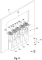
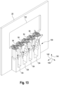
- a transfer station for transferring a container between a first module and a second module, wherein the transfer station has at least one receptacle for receiving the container, the receptacle being opened towards both modules in a transfer direction between the two modules, so that the container can be introduced into the receptacle in the transfer direction by means of a handling device of the first module and can be removed from the receptacle in the transfer direction by means of a handling device of the second module, and wherein the transfer station has a holding device for holding the container in the receptacle
- the first module and the second module can be modules of an isolator system, for example the isolator system according to the first or third aspect.
- the modules adjoin one another and are connected to one another via the transfer station.
- the modules can be a removal module, a filling module, a flanging module, a freeze-drying module, or an external washing module.
- the transfer direction is to be understood as the direction from the first to the second module.
- the transfer direction is the direction in which the container is moved when it is transferred from the first module to the second module.
- the container is inserted into the holder in the transfer direction. This means that the receptacle is opened towards the first module in such a way that the container can be introduced into the receptacle by moving in the transfer direction.
- the container is removed from the receptacle in the transfer direction.
- the container is held by means of the holding device.
- the container is held in such a way that the container can be removed in the transfer direction.
- the container can be inserted into or removed from the receptacle directly in the transfer direction, without a movement perpendicular to the transfer direction being required. This allows the container to be easily transferred between two modules, simplifying handling and increasing throughput.
- the plurality of handling devices has a first handling device and a second handling device.
- control steps in the filling module can be carried out more quickly, since the process steps can be divided between the two handling devices. In this way, individual process steps when handling several containers can be carried out at the same time, whereby the throughput rate is increased, in particular doubled.
- the step of the first transfer is carried out using the first handling device
- the step of the second transfer is carried out using the first handling device and/or the second handling device
- the step of the third transfer is carried out using the second handling device.
- a first container to be filled can be transferred for filling by means of two handling devices, while a second filled container can be transferred at the same time for plugging and/or to the second transfer station.
- individual process steps when handling several containers can be carried out at the same time, whereby the throughput rate is increased, in particular doubled.
- the filling module has an intermediate station between the filling station and the stopper setting station, wherein in the step of the second transfer the first handling device transfers the container from the filling station to the intermediate station, and the second handling device transfers the container from the intermediate station to the stopper setting station .
- step of the second transfer is carried out partly by means of the first handling device and partly by means of the second handling device.
- the isolator system further has a removal module for removing the container to be filled from a nest.
- a plurality of containers to be filled are provided in a nest.
- the nest can be introduced into the isolator in a transport tub (tub) via a transfer lock.
- the transfer lock represents a system entrance.
- the transfer lock can be designed as an H2O2 lock.
- H2O2 lock there are other options for how the transport tray can get into the removal module.
- decontamination chambers can be used using electron beam, plasma jet, gamma ray or nitrogen dioxide processes. It is also possible to work without a sterilization process by pushing or transferring the transport trays directly into the removal module after cutting open the outer bag.
- the transport tray can be inserted manually or mechanically into the transfer lock on the input side, after an outer bag in particular has been cut open around it.
- the transport tub can also be opened, the opened outer bag and/or an inner bag can be removed and/or the nest can be lifted out of the transport tub. With the lock closed, the transport trough is then decontaminated, if necessary, with a nest using hydrogen peroxide (H2O2) or one of the other methods above. Access to the removal module is then opened and processing begins.
- the removal module can have a removal station and a handling device.
- the nest can be held or placed in the removal station while the handling device removes each container individually from the nest, transfers it to the first transfer station and arranges it therein for transfer to the filling module.
- the handling device can also be designed in such a way that it can remove several, in particular two, containers from the nest at the same time and arrange them in the transfer station.
- the removal module is arranged upstream of the filling module.
- the removal module is thus arranged in front of the filling module.
- the containers are first removed from the nest and then transferred to the filling module.
- the first transfer station is arranged between the removal module and the filling module.
- the container can be removed from the removal module and transferred directly to the filling module.
- the insulator system further has a flanging module for closing the filled container.
- the crimping module can have a crimping station and one or more handling devices for handling the filled container.
- the container In the crimping station, the container is closed by means of a lid, in particular an aluminum cap. To do this, the lid is placed on the opening of the container in the crimping station and crimped onto the upper edge of the container. This process is therefore also known as “flaring”.
- the crimping station can also have a feed through which lids can be fed.
- the crimping station can be connected to a lid reservoir in which a plurality of lids are stored.
- the lid reservoir can have a separating device in which the lids are separated before they are fed individually via the feed to the crimping station.
- the filled container can be transferred from the second transfer lock to the crimping station using one or more of the handling devices.
- the supply can be carried out by providing the lids loosely on a plate.
- the position of the lids can be recognized via a sensor device, for example a camera.
- the crimping station can have a robot that, based on the detected position, picks up a lid and feeds it to the crimping station or directly to the opening of the container sets up.
- the flanging station can be designed such that several, in particular two, containers can be closed at the same time.
- the flanging module is arranged downstream of the filling module, in particular wherein the filling module is arranged between the removal module and the flanging module.
- the flanging module is thus arranged after the filling module.
- the containers are therefore first filled in the filling module and then transferred to the crimping module.
- the second transfer station is arranged between the filling module and the flanging module.
- the container can be filled in the filling module and transferred directly to the crimping module for closing.
- the isolator system further has a freeze-drying module for freeze-drying the filled containers.
- the freeze-drying module can have a freeze-dryer in which the container can be freeze-dried.
- the freeze dryer can also be arranged outside the isolator, wherein the freeze dryer can be coupled to the isolator, in particular to the freeze drying module.
- the freeze-drying module can further have one or more handling devices for handling the filled container.
- the handling devices By means of the handling devices, the container can be handled, in particular transferred, within the freeze-drying module.
- the container can be inserted into the freeze dryer using one of the handling devices and removed from the freeze dryer again after freeze drying.
- it can also be provided that one or more trays are filled with containers to be freeze dried and the freeze dryer is loaded with them.
- the trays can be unloaded from the freeze dryer and the freeze-dried containers from the tray be removed.
- the freeze dryer can be equipped with an entire batch or batch of containers. The freeze-drying process runs for several hours or days before the freeze dryer is unloaded again.
- the freeze-drying module is arranged downstream of the filling module, in particular wherein the freeze-drying module is arranged between the filling module and the crimping module.
- the container can be transferred to the freeze-drying module for freeze-drying. After freeze-drying, the container can then be transferred to the crimping module for sealing.
- the second transfer station is arranged between the filling module and the freeze-drying module.
- the container can be filled in the filling module and transferred directly to the freeze-drying module for freeze-drying.
- the isolator system further has a third transfer station between the crimping module and the freeze-drying module for transferring the container between the crimping module and the freeze-drying module.
- the container can be transferred via the third transfer station directly to the crimping module for closure. If the crimping module is arranged upstream of the freeze-drying module, the container can be transferred directly to the freeze-drying module for freeze-drying via the third transfer station after closure in the crimping module.
- the isolator system further has a transfer module for transferring the container between the filling module, the crimping module and the freeze-drying module.
- the container can be transferred from the filling module to the flanging module after filling or from the filling module to the freeze-drying module, depending on whether the container is to be freeze-dried. If the container is freeze-dried in the freeze-drying module, the container is transferred from the freeze-drying module to the flanging module after freeze-drying using the transfer module.
- the transfer module can have one or more handling devices for handling or transferring the container within the transfer module.
- the transfer module is arranged between the filling module, the crimping module and the freeze-drying module.
- the container can either be transferred from the filling module directly to the crimping module or as an intermediate station to the freeze-drying module for freeze-drying, after which the container is also transferred further to the crimping module.
- the second transfer station is arranged between the filling module and the transfer module.
- the container can be filled in the filling module and transferred directly to the transfer module for optional transfer to the crimping module or freeze-drying module.
- the isolator system further has a fourth transfer station between the transfer module and the flanging module for transferring the container between the transfer module and the flanging module, and wherein the isolator system further has between the transfer module and the freeze-drying module has a fifth transfer station for locking the container between the transfer module and the freeze-drying module.
- the container can be transferred from the transfer module directly to the crimping module after filling in the filling module or after freeze-drying in the freeze-drying module.
- the container can be transferred from the transfer module directly to the freeze-drying module after filling in the filling module.
- the isolator system further has an external washing module for external washing of the container.
- Washing the outside of a container is understood to mean that the outside of the container is freed from contaminants, in particular germs, liquid residues and/or powder residues, which occurred during the filling and/or freeze-drying and/or closing of the container.
- the container can, for example, be rinsed with a sterile liquid, in particular sterile water, and/or blown off with an inert gas or sterile air in order to remove the contamination.
- the external washing station can have an arrangement of nozzles from which sterile water for cleaning and sterile air for drying emerge.
- Cleaning agents for example caustic soda, are preferably mixed into the sterile water.
- the external washing module is arranged downstream of the flanging module.
- the container After the container has been closed, the container is washed externally in the external washing module in order to remove any contamination that may have occurred.
- the isolator system further has a sixth transfer station between the flanging module and the external washing module for transferring the container between the flanging module and the external washing module.
- the container can be closed in the flanging module and transferred directly to the external washing module for external washing.
- the isolator system has a transport device which is designed to remove the container after external washing.
- the containers can be transported away in different ways.
- the container can be pushed out into a magazine outside the isolator.
- the container can be placed on a conveyor belt with corresponding removal out of the isolator.
- the container can be placed in a transport screw with corresponding removal out of the isolator.
- a unit can be provided by means of which the container is inserted into a nest, which is transported out of the insulator with appropriate removal.
- the insulator system is designed in such a way that the container is transferred back into the removal module through the individual modules after filling and plugging in the filling module or after closing in the crimping module or after external washing in the external washing module, the removal module being added to this is designed to put the container back into the nest from which it was removed.
- the handling devices of the individual modules are preferably designed to transfer the container from the filling module or from the crimping module or from the external washing module back into the removal module.
- containers can be filled, closed or washed on the outside at the same time, while fully processed, in particular filled, closed or washed on the outside, containers are transferred back in the direction of the removal module in countercurrent.
- the individual transfer stations are designed to enable a transfer in both directions between the respective adjacent modules, in particular simultaneously.
- the handling devices can be controlled in such a way that they are on the way to a transfer station transfer a container that is still to be processed to the transfer station and, on the way back from the transfer station, remove a container that has been processed and transfer it back.
- the simultaneous transfer of the containers in both directions can be referred to as the countercurrent principle.
- the nest After being put back into the nest, the nest can be placed back into a transport tray, which is then led out of the isolator using the transfer lock or another outlet.
- the countercurrent principle does not affect the throughput of containers in the execution, or only insignificantly, since the handling devices travel the return path with or without processed containers. Using this countercurrent principle, the containers can be easily returned to the nest and discharged with it without the need for additional transport devices.
- a partition wall is arranged between successive modules of the insulator system.
- the individual modules are separated from each other by the partition walls.
- the pressure conditions in the individual modules can be different.
- the pressure in the filling module can be higher than in the remaining modules.
- the dividers allow individual pressure to be set in each module. In special applications, for example when processing toxic products, it can be provided that the pressure in the filling module is lower than in the remaining modules.
- the respective transfer station for transferring the container between the corresponding modules is arranged in each partition.
- a transfer of containers between the modules is therefore only possible via the transfer stations.
- Each transfer station thus forms a transition between the modules separated from each other by the respective partition.
- each module of the isolator system has at least two handling devices for handling the container in the corresponding module.
- control steps in each module can be carried out more quickly, since the respective process steps can be divided between the two handling devices. In this way, individual process steps when handling several containers can be carried out at the same time, whereby the throughput rate is increased, in particular doubled.
- the isolator system further has a decontamination device for decontaminating at least one module of the isolator system, wherein at least one module selected from a list comprising the filling module, the removal module, the crimping module, the freeze-drying module, the transfer module and the external washing module can be coupled to the decontamination device is to at least decontaminate the module.
- the decontamination device can, for example, gasse the coupled module with hydrogen peroxide (H2O2) to decontaminate. In this way the corresponding module is decontaminated. If several modules are connected to each other and are not isolated from each other, these modules can be decontaminated at the same time, for example by gassing them together with hydrogen peroxide.
- the isolator system can have a ventilation device by means of which the defined atmosphere is generated in the isolator.
- the ventilation device is coupled to each module of the isolator system.
- the decontamination device can be coupled to the modules of the isolator system via the ventilation device in order to gasse all modules at the same time or only specifically individual modules with H2O2 in order to contaminate these modules. During the initial decontamination at the start of production and/or at the end of production, the entire room is decontaminated across all modules.
- each transfer station can be locked in order to isolate the respective neighboring modules from one another.
- the transfer station can be closed during decontamination in order to isolate a module to be decontaminated from the neighboring modules.
- This makes it possible to specifically decontaminate an individual module, which is significantly faster than decontaminating the entire isolator system. This is particularly advantageous if contamination only occurs in a specific module and only this module needs to be decontaminated. Contamination of an individual module may be necessary if there is a disruption in the processing process of the container. In order to resolve the fault manually, it may be necessary to open an isolator door to the corresponding module. This opening makes the interior of the isolator non-sterile. If the corresponding module is isolated from the other modules, when the isolator door is opened, only the corresponding module becomes non-sterile, so that only decontamination of the individual module is required, which then only takes a short period of time.
- each transfer station has at least one receptacle for receiving the container.
- the container can be introduced into the receptacle of the transfer station using a handling device of the transferring module and removed from the receptacle again using a further handling device of the receiving module. This enables easy transfer between modules.
- the receptacle is opened in a transfer direction between the adjacent modules towards the adjacent modules, so that the container can be introduced into the receptacle in the transfer direction by means of a handling device and can be removed from the receptacle in the transfer direction by means of a handling device.
- the container can be inserted into or removed from the receptacle directly in the transfer direction, without a movement perpendicular to the transfer direction being necessary. This allows the container to be easily between two modules, simplifying handling and increasing throughput.
- each transfer station has a holding device which is designed to hold the container in the respective receptacle.
- the container is held by means of the holding device.
- the container is held in such a way that the container can be inserted or removed in the transfer direction.
- each handling device of the plurality of handling devices of the filling module is designed such that it can handle at least two containers at the same time, with the first and second transfer stations being designed such that at least two containers can be transferred simultaneously, in particular with each transfer station being at least has two receptacles for each container.
- each handling device can have two gripping tools with which two containers can be gripped and transferred at the same time.
- each module is designed such that two containers can be handled at the same time.
- each handling device can be designed in such a way that it can handle two containers at the same time.
- each handling device can have two gripping tools with which two containers can be gripped and transferred at the same time.
- each transfer station can have at least two, preferably four or more, receptacles for holding one container each.
- each station of the modules can be designed such that it can handle two containers at the same time. For example, two containers can be removed from the nest in the removal station, two containers can be filled in the filling station, two stoppers can be placed on two containers in the stopper setting station, two containers can be closed with a lid in the crimping station, two containers can be inserted in the freeze dryer or . are removed and two containers are washed on the outside in the external washing module.
- the filling station has a filling needle for dispensing the liquid, wherein in the filling step the container is filled by means of the filling needle.
- the filling needle releases the liquid into the container when filling.
- the filling needle can be arranged in the container or above an opening in the container.
- the filling needle is inserted into the container through an opening in the container for filling.
- the filling needle is arranged in the container during filling. In this way, the container can be filled more quickly with less bubble formation.
- a tip of the filling needle is arranged at the bottom of the container, and wherein in the step of moving the container is moved such that the tip of the filling needle is displaced from the bottom towards the opening of the container.
- the tip of the filling needle can be held on the surface of the liquid in the container during the filling process, thereby avoiding the formation of bubbles.
- the filling station has a weighing device for weighing the container.
- the weighing device can be used to check the amount of liquid in the container.
- control device is set up to control the first handling device in such a way that the first handling device places the container on the weighing device for weighing before filling and/or after filling.
- the amount of liquid dispensed into the container can be determined from the difference in the weight determined before and after filling as well as the density of the liquid and compared with a target value for control purposes.
- the weighing device is arranged below the filling needle.
- the container can therefore either remain on the weighing device during filling or can only be moved relative to the filling needle by means of the first handling device. In this way, construction and handling are simplified. In addition, the container does not have to be transferred to a weighing device separated in the room, which also increases the throughput rate.
- the amount of liquid dispensed into the container can be determined from the difference in the weight determined before and after filling as well as the density of the liquid and compared with a target value for control purposes.
- the container is placed on the weighing device for weighing by means of the first handling device before filling and/or after filling.
- the amount of liquid dispensed into the container can be determined and compared with a target value for control purposes.
- the filling module further has a stopper placement station for placing a stopper on the filled container.
- the stopper placement station is designed to insert a stopper into the opening of the container.
- the stopper closes the opening of the container.
- a stopper can be placed on the container in order to prevent liquid and/or gas from escaping from the container again during further processing of the container.
- a plurality of containers to be filled are provided in a nest.
- the nest can be introduced into the isolator in a transport tub (tub) via a transfer lock.
- the transfer lock represents a system entrance.
- the transfer lock can be designed as an H2O2 lock.
- H2O2 lock there are other options for how the transport tray can get into the removal module.
- decontamination chambers can be used using electron beam, plasma jet, gamma ray or nitrogen dioxide processes. It is also possible to work without a sterilization process by pushing or transferring the transport trays directly into the removal module after cutting open the outer bag.
- the transport tray can be inserted manually or mechanically into the transfer lock on the input side, after an outer bag in particular has been cut open around it.
- the transport tub can also be opened, the opened outer bag and/or an inner bag can be removed and/or the nest can be lifted out of the transport tub. With the lock closed, the transport tray is then decontaminated, if necessary with a nest, using hydrogen peroxide (H2O2) or one of the other methods above. Access to the removal module is then opened and processing begins.
- the removal module can have a removal station and a handling device.
- the nest can be held or placed in the removal station while the handling device removes each container individually from the nest, transfers it to the first transfer station and arranges it therein for transfer to the filling module.
- the handling device can also be designed in such a way that it can remove several, in particular two, containers from the nest at the same time and arrange them in the transfer station.
- the crimping module can have a crimping station and one or more handling devices for handling the filled container.
- the container In the crimping station, the container is closed by means of a lid, in particular an aluminum cap. To do this, the lid is placed on the opening of the container in the crimping station and crimped onto the upper edge of the container. This process is therefore also known as “flaring”.
- the crimping station can also have a feed through which lids can be fed.
- the crimping station can be connected to a lid reservoir in which a plurality of lids are stored.
- the lid reservoir can have a separating device in which the lids are separated before they are fed separately via the feed to the crimping station.
- the filled container can be transferred from the second transfer lock to the crimping station using one or more of the handling devices.
- the supply can be carried out by providing the lids loosely on a plate.
- the position of the lids can be recognized via a sensor device, for example a camera.
- the crimping station can have a robot that, based on the detected position, picks up a lid and feeds it to the crimping station or places it directly on the opening of the container.
- the flanging station can be designed such that several, in particular two, containers can be closed at the same time.
- the freeze-drying module can have a freeze-dryer in which the container can be freeze-dried.
- the freeze dryer can also be arranged outside the isolator, wherein the freeze dryer can be coupled to the isolator, in particular to the freeze drying module.
- the freeze-drying module can further have one or more handling devices for handling the filled container.
- the handling devices By means of the handling devices, the container can be handled, in particular transferred, within the freeze-drying module.
- the container can be inserted into the freeze dryer using one of the handling devices and removed from the freeze dryer again after freeze drying.
- it can also be provided that one or more trays are filled with containers to be freeze dried and the freeze dryer is loaded with them.
- the trays can be unloaded from the freeze dryer and the freeze-dried containers removed from the tray.
- the freeze dryer can be equipped with an entire batch or batch of containers. The freeze-drying process runs for several hours or days before the freeze dryer is unloaded again.
- the container can be transferred after filling either from the filling module to the crimping module or transferred from the filling module to the freeze-drying module, depending on whether the container is to be freeze-dryed. If the container is freeze-dried in the freeze-drying module, after freeze-drying the container is transferred from the freeze-drying module to the crimping module by means of the transfer module.
- the transfer module can have one or more handling devices for handling or transferring the container within the transfer module.
- Washing the outside of a container is understood to mean that the outside of the container is freed from contaminants, in particular germs, liquid residues and/or powder residues, which occurred during the filling and/or freeze-drying and/or closing of the container.
- the container can, for example, be rinsed with a sterile liquid, in particular sterile water, and/or blown off with an inert gas or sterile air in order to remove the contamination.
- the external washing station can have an arrangement of nozzles from which sterile water for cleaning and sterile air for drying emerge.
- Cleaning agents in particular caustic soda, are preferably mixed into the sterile water.
- the containers can be transported away in different ways.
- the container can be pushed out into a magazine outside the isolator.
- the container can be placed on a conveyor belt with corresponding removal out of the isolator.
- the container can be placed in a transport screw with corresponding removal out of the isolator.
- a unit can be provided by means of which the container is inserted into a nest, which is transported out of the insulator with appropriate removal.
- the handling devices of the individual modules are preferably designed to transfer the container from the filling module or from the crimping module or from the external washing module back into the removal module.
- containers can be filled, closed or washed on the outside at the same time, while fully processed, in particular filled, closed or washed on the outside, containers are transferred back in the direction of the removal module in countercurrent.
- the individual transfer stations are designed to: they enable, especially at the same time, a transfer in both directions between the respective adjacent modules.
- the handling devices can be controlled in such a way that on the way to a transfer station they transfer a container that is still to be processed to the transfer station and on the way back from the transfer station they remove a finished container and transfer it back.
- the simultaneous transfer of the containers in both directions can be referred to as the countercurrent principle.
- the nest After being put back into the nest, the nest can be placed back into a transport tray, which is then led out of the isolator using the transfer lock.
- the countercurrent principle does not affect the throughput of containers in the execution, or only insignificantly, since the handling devices travel the return path with or without processed containers. Using this countercurrent principle, the containers can be easily returned to the nest and discharged with it without the need for additional transport devices.
- the decontamination device can, for example, gasse the coupled module with hydrogen peroxide (H2O2) to decontaminate. In this way the corresponding module is decontaminated. If several modules are connected to each other and are not isolated from each other, these modules can be decontaminated at the same time, for example by gassing them together with hydrogen peroxide.
- the isolator system can have a ventilation device by means of which the defined atmosphere is generated in the isolator.
- the ventilation device is coupled to each module of the isolator system.
- the decontamination device can be connected via the ventilation device
- Modules of the isolator system can be coupled in order to gasse all modules at the same time or only specifically individual modules with H2O2 in order to contaminate these modules. During the initial decontamination at the start of production, the entire room is decontaminated across all modules.
- the transfer station can be closed during decontamination in order to isolate a module to be decontaminated from the neighboring modules.
- This makes it possible to specifically decontaminate an individual module, which is significantly faster than decontaminating the entire isolator system. This is particularly advantageous if contamination only occurs in a specific module and only this module needs to be decontaminated. Contamination of an individual module may be necessary if there is a disruption in the processing process of the container. In order to resolve the fault manually, it may be necessary to open an isolator door to the corresponding module. This opening makes the interior of the isolator non-sterile. If the corresponding module is isolated from the other modules, when the isolator door is opened, only the corresponding module becomes non-sterile, so that only decontamination of the individual module is required, which then only takes a short period of time.
- the container can be introduced or inserted into the receptacle of the transfer station using a handling device of the transferring module and removed from the receptacle again using a further handling device of the receiving module. This enables easy transfer between modules.
- the receptacle is designed to accommodate different containers with different geometries
- the holding device is designed such that it can hold the different containers in the receptacle, in particular the different containers have different diameters.
- the transfer station is set up so that different types of containers can be transferred between the modules. This can increase the flexibility of the system.
- various format parts can be dispensed with.
- the containers such as vials, syringes, bottles, cylinder ampoules, are preferably cylindrical. In other words, these containers are circular cylindrical in cross section. However, the diameters of the containers can be different.
- the holding device can be designed to be variable or flexible in such a way that it can adapt to the diameter of the container.
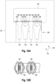
- the holding device has elastic elements which are arranged opposite on the receptacle perpendicular to the transfer direction, the elastic elements being arranged in such a way that they are pressed apart when a container is arranged between the elastic elements.
- the elastic elements are arranged so close to one another that when the container is inserted into the receptacle, the elastic elements are pushed apart. Depending on the container diameter, the elastic elements pushed far apart accordingly.
- the clamping elements in particular the clamping elements designed as spring elements or elastic elements, can form a prism into which the objects fit. When compressed, the prism contours shift so that the theoretical center always remains in the middle of the holding device. In this way, objects with different diameters can be held in the same position using the clamping elements.
- the holding device has a pretensioning device which is designed to clamp the container transversely, in particular perpendicularly, to the transfer direction.
- the container is clamped in the receptacle perpendicular to the transfer direction when the container has been placed in the receptacle.
- the insertion and removal of the container takes place in the transfer direction, so that the clamping of the container does not hinder the insertion and removal of the container.
- the elastic elements can be designed to build up a preload force when they are pushed apart perpendicular to the transfer direction.
- the transfer station is designed to accommodate a plurality of containers, and the transfer station has a plurality of receptacles for accommodating one container each.
- the number of the plurality of recordings is an even number, in particular two, four or six.
- the same number of containers can be handled from both sides of the transfer station.
- the second module can remove containers from half of the receptacles, while the first module inserts containers into the other half of the receptacles.
- the same number of containers could be transferred in each half of the receptacles in both directions, i.e. from the first to the second module and from the second to the first module.
- the transfer station can be locked in order to isolate the modules from each other.
- the transfer station can be closed during a decontamination cycle in order to isolate a module to be decontaminated from the neighboring modules.
- This makes it possible to specifically decontaminate an individual module, which is significantly faster than decontaminating the entire isolator system. This is particularly advantageous if contamination only occurs in a specific module and only this module needs to be decontaminated.
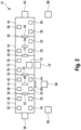
- Fig. 1 shows a first embodiment of an isolator system 10 for filling one or more containers.
- the isolator system 10 can be designed as an aseptic isolator, in particular as a clean room or ultra-clean room.
- the insulator system 10 has a removal module 12, a filling module 14, a flanging module 16 and an external washing module 18.
- the filling module 14 is arranged between the removal module 12 and the flanging module 16.
- the flanging module 16 is arranged between the filling module 14 and the external washing module 18.
- the modules 12, 14, 16, 18 are separated from each other by partitions 20.
- a transfer station 22, 24, 26 is arranged in each partition wall, by means of which containers can be transferred between the adjacent modules.
- the transfer station 22 is arranged between the removal module 12 and the filling module 14.
- the transfer station 22 can also be referred to as the first transfer station.
- the transfer station 24 is arranged between the filling module 14 and the flanging module 16.
- the transfer station 24 can also be referred to as a second transfer station.
- the transfer station 26 is arranged between the flanging module 16 and the external washing module 18.
- the isolator system 10 also has a control device 68.
- the control device 68 is set up to control the functions of the individual modules 12, 14, 16, 18.
- the removal module 12 is designed to remove one or more containers from a nest.
- the removal module 12 has a removal station 28 in which containers can be removed from the nest.
- the removal module 12 also has a handling device 30.
- the handling device 30 is designed to handle one or more containers within the removal module.
- the control device 68 controls the handling device 30 such that the handling device 30 removes a container from the nest in the removal station 28 and transfers the container to the transfer station 22.
- the control device 68 can control the handling device 30 in such a way that the containers are removed one after the other from the nest and transferred to the transfer station 22.
- the removal module 12 adjoins a transfer lock 36, in which a nest with containers can be provided to the removal module 12.
- the nest can be arranged in a transport tray.
- the transport tray can be closed using a film.
- the transfer lock can be designed as an H2O2 lock, in which a transport tray placed in the isolator can be decontaminated using H2O2 gassing.
- the removal module 12 also has an unpacking station 32.
- the film can be removed from the transport tray in the unpacking station 32.
- the removal module 12 can further have one or more further handling devices 34, by means of which the nest can be handled within the removal module 12.
- the handling devices 34 By means of the handling devices 34, the transport tub with the nest packed therein can be transferred from the transfer lock to the unpacking station. After removing the film, the transport tub with nest can be transferred to the removal station 28. Before the handling device 30 removes individual containers from the nest, the nest can be removed from the transport tub using the handling devices 34.
- the filling module 14 is designed to fill one or more containers with a liquid.
- the filling module 14 has a filling station 38 in which a container can be filled.
- the filling station 38 can have one or more filling needles for dispensing the liquid.
- the filling module 14 further has a stopper placement station 40 in which a stopper can be placed on one or more containers.
- the plug setting station 40 has means for placing a plug.
- the filling module 14 further has a first handling device 42 and a second handling device 44.
- the handling devices 42, 44 are designed to handle one or more containers within the filling module 14.
- the control device 68 controls the first handling device 42 such that the first handling device 42 removes a container from the first transfer station 22 and transfers it to the filling station.
- the container is filled in the filling station.
- the control device 68 controls the filling station 38 to fill the container.
- the control device 68 controls the first and/or the second handling device 42, 44 such that the filled container is transferred from the filling station 38 to the stopper setting station.
- a stopper is placed on the container.
- the control device 68 controls the plug setting station 40 to place the plug.
- the control device 68 controls the second handling device 44 in such a way that the second handling device 44 transfers the container from the stopper setting station 40 to the second transfer station 24 and delivers it to the second transfer station 24.
- An intermediate station 46 which is designed as a transfer station, can be arranged between the filling station 38 and the stopper setting station 40.
- the control device 68 can control the first and second handling devices 42, 44 such that the first handling device 42 moves the container from the filling station 38 to the intermediate station 46 transferred and the second handling device 44 transferred the container from the intermediate station 46 to the stopper setting station 40.
- the flanging module 16 is designed to close one or more containers.
- the flanging module 16 has a flanging station 48 in which one or more containers can be closed.
- the containers in the crimping station 48 can be closed by means of a lid, in particular an aluminum cap.
- the lid is placed on the opening of the corresponding container in the crimping station 48 and crimped on the upper edge of the container.
- the flanging module 16 further has a handling device 50, by means of which one or more containers within the flanging module 16 can be handled.
- the flanging module 16 can also have a further handling device 52, by means of which a container can also be handled within the flanging module 16.
- the control device 68 controls the handling device 50 such that the handling device removes a filled container from the transfer station 24 and transfers it to the flanging station 48.
- the container is closed in the flanging station 48.
- the control device 68 controls the crimping station 48 to close the container.
- the control device 68 controls the handling devices 50, 52 such that one of the handling devices 50, 52 transfers the container from the crimping station 48 to the transfer station 26 and delivers it to the second transfer station 26.
- An intermediate station 54 which is designed as a transfer station, can be arranged between the flanging station 48 and the transfer station 26.
- the control device 68 can control the handling devices 50, 52 such that the handling device 50 transfers the container from the crimping station 48 to the intermediate station 54 and the handling device 52 transfers the container from the intermediate station 46 transferred to the transfer station 26.
- the external washing module 18 is designed to externally wash one or more containers.
- the external washing module 18 has an external washing station 56 in which one or more containers can be washed externally.
- the external washing module 18 further has a handling device 58, by means of which one or more containers within the external washing module 18 can be handled.
- the external washing module 18 can also have a further handling device 60, by means of which one or more containers can additionally be handled within the external washing module 18.
- the external washing module 18 can adjoin a transfer lock 62, from which one or more containers can be discharged.
- the discharged container can then be removed via another transport device.
- a transfer lock instead of discharging the containers via a transfer lock, it can be provided that the containers are pushed out into a magazine outside the isolator.
- the containers can be placed on a conveyor belt with corresponding removal out of the isolator.
- the containers can also be placed in a transport screw with corresponding removal out of the isolator.
- a unit can also be provided by means of which the container is inserted into a nest, which is transported out of the insulator with appropriate removal.
- the control device 68 controls the handling device 58 such that the handling device 58 removes a closed container from the transfer station 24 and transfers it to the external washing station 56. The outside of the container is washed in the outside washing station 56. After external washing, the control device 68 controls one of the handling devices 58, 60 such that one of the handling devices 58, 60 transfers the container from the external washing station 56 to the transfer lock 62 and arranges it in this.
- the filling module 14 can have a door 64. Access from the outside into the insulator system 10, in particular into the filling module 14, is provided via the door 64. Over The door 64 can be used for manual intervention in the filling module 14, for example if there is a fault in the filling module 14.
- the isolator system 10 can further have a ventilation device 65, by means of which a defined atmosphere can be generated in the isolator system.
- Each of the modules of the isolator system 10 can be coupled to a decontamination device 66.
- the decontamination device 66 is designed to decontaminate the module to which it is coupled.
- the decontamination device 66 can gasse the corresponding module with hydrogen peroxide.
- the control device 68 can control the decontamination device 66.
- the decontamination device 66 can be coupled to the individual modules via the ventilation device 65 in order to gasse the individual modules with hydrogen peroxide.
- Fig. 2 shows a second embodiment of the insulator system 10.
- the insulator system 10 of the second embodiment has essentially the same elements as the insulator system 10 of the first embodiment. The same elements are marked with the same reference numbers and are not explained in more detail.
- the isolator system 10 of the second embodiment additionally has a freeze-drying module 70.
- the freeze-drying module 70 is arranged between the filling module 14 and the flanging module 16.
- the transfer station 24 is arranged between the filling module 14 and the freeze-drying module 70.
- Another transfer station 72 is arranged between the freeze-drying module 70 and the flanging module 16.
- the freeze-drying module 70 is designed to freeze-dry one or more containers.
- the freeze-drying module 70 has a freeze dryer 74.
- the freeze dryer 74 is designed to freeze-dry filled containers.
- freeze dryer 74 can also be arranged outside the freeze drying module 70, in particular outside the isolator, with the freeze dryer 74 being coupled to the freeze drying module 70.
- the freeze-drying module 70 can be designed to load the freeze-dryer 74 with containers to be freeze-dryed and to unload the freeze-dried containers from the freeze-dryer again after freeze-drying.
- the freeze-drying module 70 further has a handling device 76, by means of which one or more containers within the freeze-drying module 70 can be handled.
- the freeze-drying module 70 can also have a further handling device 78, by means of which a container can additionally be handled within the freeze-drying module 70.
- the control device 68 controls the handling device 76 such that the handling device 76 removes a filled container from the transfer station 24 and transfers it to the freeze dryer 74.
- the handling device 76 inserts the container into the freeze dryer 74.
- the container is freeze-dried in the freeze dryer 74.
- the control device 68 controls one of the handling devices 76, 78 such that one of the handling devices 76, 78 transfers the container from the freeze dryer 74 to the transfer station 26 and arranges it in this.
- Fig. 3 shows a third embodiment of the insulator system 10.
- the insulator system 10 of the third embodiment has essentially the same elements as the insulator system 10 of the second embodiment. The same elements are marked with the same reference numbers and are not explained in more detail.
- the isolator system 10 of the third embodiment additionally has a transfer module 80, which is arranged between the filling module 14, the crimping module 16 and the freeze-drying module 70.
- the transfer station 24 is arranged between the filling module 14 and the transfer module 80.
- Another transfer station 82 is arranged between the transfer module 80 and the flanging module 16.
- Another transfer station 84 is arranged between the transfer module 80 and the freeze-drying module 70.
- the transfer module 80 is designed to transfer one or more containers between the filling module 14, the crimping module 16 and the freeze-drying module 70.
- the transfer module 80 has a handling device 86, by means of which a container can be handled within the transfer module 80.
- the transfer module 80 can also have a further handling device 88, by means of which a container can also be handled within the transfer module 80.
- the handler 76 removes a filled container from the transfer station 84 and transfers the container to the freeze dryer 74 for freeze drying. After freeze-drying, the container is transferred back to the transfer station 84 by means of one of the handling devices 76, 78.
- the containers are transferred back into the removal module 12 after filling and plugging in the filling module 14 or closing in the crimping module 16 or after external washing in the external washing module 18 in order to reinsert the containers into the nest from which they were taken.
- the containers can be transferred in the opposite direction using the handling devices of the individual modules.
- Each module 12, 14, 16, 18, 70, 80 may be designed to handle two or more containers simultaneously.
- each handling device 30, 42, 44, 50, 52, 58, 60 can be designed such that it can handle two containers at the same time.
- each handling device 42, 44, 50, 52, 58, 60 can have two gripping tools with which two containers can be gripped at the same time can be transferred.
- each transfer station 22, 24, 26, 72, 82, 84 can have at least two, preferably four or more, receptacles for receiving one container each.
- each station of the modules 12, 14, 16, 18, 70, 80 can be designed such that it can handle two containers at the same time.
- two containers can be removed from the nest, in the filling station 38 two containers can be filled, in the stopper setting station 40 two stoppers can be placed on two containers, in the flanging station 48 two containers can be closed with a lid, in the freeze dryer 74 two containers are inserted or removed and two containers are washed on the outside in the external washing station 56.
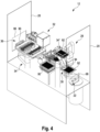
- Fig. 4 shows an embodiment of a removal module 12 of the isolator system 10.
- Fig. 5 the removal station 28 of the removal module 12 is shown in detail.
- the removal module 12 has two handling devices 34', 34" for handling the nests.
- the handling devices 30, 34' and 34" are designed as robots.
- the handling devices 30, 34' and 34" each have an end effector 102, by means of which the transport tub 90, the nest 92 and/or the containers 94 can be handled.
- the handling devices 30, 34' and 34" each have a support structure 100, by means of which the corresponding end effector 102 can be moved in the removal module 12.
- the end effector 102 of the handling device 30 can have, for example, a gripping tool.
- the gripping tool is preferably designed such that two containers 94 can be gripped and transferred at the same time.
- the removal module 12 is separated from the transfer lock 36 by means of a partition 20.
- the partition 20 has an opening 96 through which the removal module 12 is connected to the transfer lock 36.
- the opening 96 can be closable in order to isolate the transfer lock 36 and the removal module 12 from one another.
- a handling device 34 'of the handling devices 34 can remove a transport tub 90 provided in the transfer lock 36 and transfer to the unpacking station 32.
- a nest 92 is arranged in each transport tub 90.
- a plurality of containers 94 are arranged in each nest 92.
- Each transport tray 90, which is provided in the transfer lock 36, is closed with a film.
- the film is removed from the transport tub 90 in order to unpack the transport tub 90, in particular to open it.
- the handling device 34 transfers the unpacked transport tub 90 further to the removal station 28.
- the handling device 34' can place the transport tub 90 in a holder in the removal station 28.
- the nest 92 can be removed from the transport tub 90 and transferred to a further holder of the removal station 28 and placed there.
- the removal module 12 is separated from the filling module 14 by means of a partition 20.
- the partition 20 has an opening 98 through which the removal module 12 is connected to the filling module 14.
- the transfer station 22 is arranged in the opening 98.
- the transfer station 22 can have at least one receptacle for holding a container 94. In particular, the transfer station 22 has at least two receptacles.
- the containers 94 are removed from the nest 92 and transferred to the transfer station 22.
- the handling device 30 can each arrange the removed containers 94 in a receptacle in the transfer station 22. In the transfer station 22, the containers are transferred from the removal module 12 to the filling module 14. In particular, the containers 94 can be removed from the nest 92 individually or in pairs using the handling device 30 and transferred to the transfer station 22.
- the empty nest 92 can be placed back into the associated transport trough 90 by means of the handling device 34 ".
- the transport trough 90 can then be transferred to the transfer lock 36 or to another ( (not shown) transfer lock be transferred in order to remove the transport tub 90 with an empty nest 92 from the removal module.
- filled, closed and/or externally washed containers 94 are introduced back into the removal module via the transfer station 22 in order to place these containers back into the nest 96 from which they were removed.
- the nest which is again filled with containers, can then be discharged using the handling devices 34', 34".
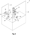
- Fig. 6 shows an embodiment of a filling module 14 of the insulator system 10.
- Fig. 7 the filling station 38 of the filling module 14 is shown in detail.
- Fig. 8 the plug setting station 40 of the filling module 14 is shown in detail.
- the handling devices 42 and 44 are designed as robots.
- the handling devices 42 and 44 each have an end effector 102 by means of which the containers 94 can be handled. Furthermore, the handling devices 42 and 44 each have a support structure 100, by means of which the corresponding end effector 102 can be moved in the filling module 14.
- the end effector 102 of the handling devices 42 and 44 can have, for example, a gripping tool.
- the gripping tool is preferably designed such that two containers 94 can be gripped and transferred at the same time.
- the containers 94 are transferred from the transfer station 22 to the filling station.
- the containers 94 can be removed from the transfer station 22 either individually or in pairs by means of the handling device 42 and transferred to the filling station.
- the filling station 38 has two filling needles 106, two filling needle holders 108 for holding the filling needles 106, two metering devices (not shown) and two weighing devices 110.
- Each filling needle 106 is designed to dispense liquid into a container 94. To dispense the liquid, each filling needle 106 can either be positioned above an opening of the container 94 or inserted into the container 94 through the opening.
- Each dosing device is designed to regulate the amount of liquid to be dispensed from each filling needle 106.
- the filling needles can be used with a Tank be connected, which serves as a liquid reservoir.
- Each metering device is arranged in a fluid path between the tank and the corresponding filling needle 106.
- Each weighing device 110 is designed to determine the weight of a container 94 that is placed on the weighing device 110.
- Each weighing device 110 is arranged under a filling needle 106.
- the containers 94 can be placed individually or in pairs on the weighing device 110 and weighed before filling.
- the first handling device 42 can lift the weighed containers 94 again and move them upwards towards the respective filling needle 106 in order to insert the filling needle 106 into the respective container 94 to be filled.
- the filling needle 106 can be inserted into the container 94 until a tip of the filling needle 106 is arranged at the bottom of the container 94.
- On the ground means that the tip is either placed on the ground or is arranged near the ground.
- the tip of the filling needle can be arranged just above the bottom.
- a distance between the tip of the filling needle 106 and the bottom of the container 94 can be between at least 1 mm and 2 cm, preferably between 2 mm and 1 cm, in particular 3 mm.
- the container 94 is moved downward again by means of the handling device 42, so that a distance between the bottom of the container 94 and the tip of the filling needle 106 increases. In other words, the filling needle 106 is pulled out of the container 94 during filling.
- each container 94 is placed back on the weighing device 110 and weighed a second time.
- the filling quantity can be determined from the difference in weight between the first and second weighing of a container.
- the determined filling quantity can be compared with a target filling quantity for quality control purposes.
- the containers can be transferred individually or in pairs from the filling station 38 to the stopper setting station 40.
- the stopper setting station 40 has a stopper setting device 112 by means of which a stopper can be placed on a container. Using the stopper setting device 112, two stoppers can also be placed on two containers at the same time.
- the stopper setting station 40 may further have two holders 114 for two containers 94. The holders 114 are arranged under the plug setting device 112.
- the containers are placed individually or in pairs under the stopper setting device 112.
- one container can be placed on each holder.
- the stopper setting device 112 then places one stopper on each container one after the other.
- the stopper setting device 112 can also place two stoppers simultaneously on two containers 94 arranged in the stopper setting station 40.
- the filling module 14 is separated from the subsequent module by means of a partition 20.
- the subsequent module can be the flanging module 16, the freeze-drying module 70 or the transfer module 80.
- the partition 20 has an opening 104 through which the filling module 14 is connected to the subsequent module.
- the transfer station 24 is arranged in the opening 104.
- the transfer station 24 can have at least one receptacle for holding a container 94. In particular, the transfer station 24 has at least two receptacles.
- the containers 94 are transferred individually or in pairs from the stopper setting station 40 to the transfer station 24 after the stopper has been placed.
- the handling device 44 can each arrange the containers 94 in a receptacle in the transfer station 24. In the transfer station 24, the containers are transferred from the filling module 14 to the subsequent module.
- Fig. 9 shows an embodiment of a flanging module 16 of the insulator system 10.
- Fig. 10 the flanging station 48 of the flanging module 16 is shown in detail.
- the handling device 50 is designed as a robot.
- the handling device 50 has an end effector 102, by means of which the containers 94 are handled can.
- the handling device 50 has a support structure 100, by means of which the corresponding end effector 102 can be moved in the filling module 14.
- the end effector 102 of the handling device 50 can, for example, have a gripping tool.
- the gripping tool is preferably designed such that two containers 94 can be gripped and transferred at the same time.
- the flanging module 16 is separated from the previous module by means of a partition wall 20.
- the previous module can be the filling module 14, the freeze-drying module 70 or the transfer module 80.
- the partition wall 20 has an opening 116 through which the flanging module 16 is connected to the previous module.
- the corresponding transfer station 24, 72, 82 to the previous module is arranged in the opening 116.
- the transfer station 24, 72, 82 can have at least one receptacle for receiving a container 94. In particular, the transfer station 24, 72, 82 has at least two receptacles.
- the containers 94 are transferred from the transfer station 24, 72, 82 to the flanging station 48.
- the containers 94 can be removed from the transfer station 24, 72, 82 either individually or in pairs by means of the handling device 50 and transferred to the crimping station 48.
- the containers 94 are closed individually or in pairs one after the other.
- the containers 94 in the crimping station 48 can be closed by means of a lid.
- the lid is placed on the opening of the container 94 in the crimping station 48 and crimped on the upper edge of the container 94.
- the flanging station 48 can have two flanging devices 120. Each flanging device 120 is designed to close one container 94 each.
- the flanging module 16 is separated from the external washing module 18 by means of a partition 20.
- the partition 20 has an opening 118 through which the flanging module 16 is connected to the external washing module 18.
- the transfer station 26 is arranged in the opening 118.
- the transfer station 26 can accommodate at least one recording a container 94.
- the transfer station 26 has at least two receptacles.
- the containers 94 are transferred individually or in pairs from the crimping station 48 to the transfer station 26 after crimping.
- the handling device 50 can each arrange the containers 94 in a receptacle in the transfer station 26. In the transfer station 26, the containers are transferred from the filling module 14 to the external washing module 18.
- the Figures 11 to 15 show an embodiment of a transfer station 130.
- Each transfer station 22, 24, 26, 72, 82, 84 of the isolator system 10 from the Figures 1 to 3 can be selected according to the transfer station Figures 11 to 15 be trained.
- the transfer station 130 can be arranged in an opening 132 of a partition 20 between two modules.
- the transfer station 130 is designed so that at least one container 94 can be transferred between a first module and a second module.
- the transfer station 130 can be designed so that a plurality of containers 94 can be transferred simultaneously by means of the transfer station 130.
- the containers 94 are transferred in a transfer direction 140 from the first module to the second module.
- the partition 20 is arranged transversely, preferably perpendicular to the transfer direction 140 and extends in a vertical direction 144 and a horizontal direction 142.
- the vertical direction 144 and the horizontal direction 142 are arranged transversely, preferably perpendicular to the transfer direction 140.
- the opening 132 also extends in the vertical direction 144 and the horizontal direction 142. In other words, the opening 132 forms a recess in the partition 20 through which the containers 94 can be passed in the transfer direction 140.
- the transfer station 130 has at least one receptacle 134 for holding a container 94.
- the transfer station 130 can have a plurality of receptacles 134 for each holding a container 94.
- the transfer station 130 has four receptacles 134.
- Each receptacle 134 is open to both modules in the transfer direction 140.
- one container 94 can be introduced into the respective receptacle 134 in the transfer direction 140 by means of a handling device of the first module.
- one container 94 can be removed from the respective receptacle 134 in the transfer direction 140 by means of a handling device of the second module.
- each receptacle 134 is open on both sides in the transfer direction 140, so that a container 94 can be introduced into the receptacle 134 in the transfer direction 140 and removed from the receptacle 134.
- Each receptacle 134 is U-shaped. Each receptacle has two side surfaces and a bottom surface. The two side surfaces are spaced apart in the horizontal direction 142. The bottom surface is arranged between side surfaces and forms a lower end of the receptacle 134 with respect to the vertical direction 144. The upper end of the receptacle 134 is open. A distance between the side surfaces in the horizontal direction 142 is so large that a container 94 can be arranged between the side surfaces.
- Each receptacle 134 is further designed such that different containers 94 (for example syringes, vials, bottles, cylinder ampoules, and the like) with different geometry can be accommodated in each receptacle 134.
- the distance between the side surfaces in the horizontal direction 142 is so large that containers 94 with different diameters can be accommodated in each receptacle 134.
- the transfer station 130 further has a holding device 136 for each receptacle 134 for holding the container 94 in the corresponding receptacle 134.
- the holding device has a biasing device which is designed to hold the container 94 to clamp transversely, preferably perpendicularly, to the transfer direction 140.
- the biasing device can be designed to clamp the container 94 in the horizontal direction 142.
- each holding device 136 is formed by a first clamping element 138' and a second clamping element 138".
- the clamping elements 138', 138" are spaced apart from one another in a clamping direction.
- the clamping direction is arranged transversely, preferably perpendicularly, to the transfer direction 140. In particular, the clamping direction can be arranged parallel to the horizontal direction 142.
- the clamping elements 138', 138" are arranged at the upper end of the respective receptacle 134.
- the clamping elements 138', 138" are designed to be elastic at least in the horizontal direction 142.
- the clamping elements 138', 138" can therefore also be referred to as elastic elements.
- the clamping elements 138', 138" can be designed, for example, as spring elements which are arranged such that a distance between the clamping elements 138', 138" in the horizontal direction 142 can be varied compared to a rest state.
- the clamping elements 138', 138" are biased towards the rest state.
- the clamping elements can in particular be designed as triangular brackets, with the brackets of the clamping elements 138', 138" being arranged mirror-symmetrically to one another. In particular, blunt corners of the brackets are arranged opposite each other.
- the clamping elements 138', 138 in particular the clamping elements 138', 138" designed as spring elements or elastic elements, can form a prism into which the objects fit, as shown in the top view of Figure 12B can be seen. When compressed, the prism contours shift so that the theoretical center always remains in the middle of the holding device. In this way, objects with different diameters can be held in the same position using the clamping elements 138', 138".
- the distance between the clamping elements 138', 138" in the horizontal direction 142 is smaller in the idle state than a distance between the side surfaces of the receptacle 134 in the horizontal direction 142. Furthermore, the distance between the clamping elements 138', 138" in the horizontal direction 142 in the rest state is equal to or smaller than the diameter of the container 94 in a clamping section.
- the clamping portion of the container is preferably a portion of the container located below the opening of the container.
- the clamping section can be a neck section of a bottle neck of the container.
- the distance between the clamping elements 138', 138" in the horizontal direction 142 can in particular be equal to or smaller than the smallest diameter of the containers 94.
- the container 94 In order to introduce a container 94 into one of the receptacles 134, the container 94 is moved from the first module into the receptacle in the transfer direction 140 until it is arranged in the receptacle 134, in particular until the container 94 is between the clamping elements 138 ', 138 "
- the container When the container 94 has been inserted into the receptacle 134, the container is clamped perpendicular to the transfer direction 140 by means of the holding device 136.
- the container 94 is inserted between the clamping elements 138 ', 138".
- the clamping elements 138', 138" are pressed apart.
- the clamping elements 138', 138" are further spaced apart from one another in the clamping direction, so that a preload force is built up for clamping the container.
- the pretensioning force pulls the clamping elements 138 ', 138" together, thereby clamping the container 94.
- the container 94 is moved further out of the receptacle 134 in the transfer direction 140 towards the second module, until the container is arranged outside the receptacle 134.
- each holding device 136 can be designed in such a way that it can hold different containers 94 with different geometries in the respective receptacle 134.
- the clamping elements 138', 138" are arranged so close to one another that when the container 94 is inserted into the receptacle 134, the container pushes the clamping elements 138', 138" apart. Depending on the container diameter, the clamping elements 138', 138" are pushed apart accordingly. In this way, it is achieved that different containers 94 with different geometries, in particular with different diameters, can be held in the receptacle 134 by means of the holding device 136.
- the transfer station 130 can also be lockable in order to isolate the modules from one another.
- the transfer station 130 can, for example, have a covering device by means of which at least one side of the opening 132 can be completely covered.
- two containers 94 are arranged in two of the four receptacles 134.
- the containers 94 are designed as bottles.
- FIG. 13 and 14 Four containers are arranged in the four receptacles 134.
- a container 94 is arranged in each receptacle 134.
- the containers 94 are designed as syringes.
- a Petri dish 146 can also be transferred using the transfer station 130.
- the Petri dish 146 can be placed in the opening 132 on the transfer station 130.
- the Petri dish 146 can rest on the clamping elements 138 ', 138" of the holding device 136.
- the transfer station 130 can have support elements 148 on which the Petri dish 146 can be placed.
- the support elements 148 are arranged between the receptacles 134.
- the support elements 148 extend higher in the vertical direction 144 than the receptacles 134 and the holding devices 136.
- the support elements 148 can be designed as knobs.
- Fig. 16 shows a first embodiment of a method 160 for filling a container 94 with a liquid in a filling module 14.
- the method 160 can be made of one of the following by means of the isolator system 10 Figures 1 to 3 be performed.
- the control device 68 of the isolator system 10 can be designed to control the isolator system 10 in accordance with the method steps of the method 160.
- the container 94 to be filled is arranged in the first transfer station 22 for transferring the container 94 into the filling module 14.
- the container is removed from a receptacle of the first transfer station 22 by means of a handling device of the plurality of handling devices 42, 44 of the filling module 14, the first transfer station 22 having at least one receptacle for the container 94.
- the container 94 is removed from the receptacle of the transfer station 22 in particular by means of the first handling device 42.
- the container 94 is transferred from the first transfer station 22 to the filling station 38 of the filling module 14 by means of one or more handling devices of the plurality of handling devices 42, 44 of the filling module 14.
- the container 94 is transferred from the transfer station 22 to the filling station 38 in particular by means of the first handling device 42.
- the container 94 in the filling station 38 is filled with the liquid.
- the container 94 is transferred from the filling station 38 to the stopper setting station 40 by means of one or more handling devices of the plurality of handling devices 42, 44 of the filling module 14.
- the container 94 is transferred from the transfer station 22 to the filling station 38 in particular by means of the first and/or the second handling device 42, 44.
- the first handling device 42 may transfer the container 94 from the filling station 38 to the intermediate station 46 and the second handling device 44 may transfer the container 94 from the intermediate station 46 to the plugging station 40.
- a stopper is placed on the container 94.
- the container 94 is handled by means of one or more handling devices of the plurality of handling devices 42, 44 of the filling module 14 is transferred from the stopper setting station 40 to the second transfer station 24.
- the container 94 is transferred from the stopper setting station 40 to the second transfer station 24 in particular by means of the second handling device 44.
- the container 94 is inserted or introduced into a receptacle of the second transfer station 24 by means of one or more handling devices of the plurality of handling devices 42, 44 of the filling module 14, the second transfer station 24 having at least one receptacle for the container 94 having.
- the container 94 is inserted into the receptacle of the transfer station 24 in particular by means of the second handling device 44.
- Fig. 17 shows a second embodiment of a method 180 for filling a container 94 with a liquid in a filling module 14.
- the method 180 can be made by means of the isolator system 10 from one of the Figures 1 to 3 be performed.
- the control device 68 of the isolator system 10 can be designed to control the isolator system 10 in accordance with the method steps of the method 180.
- Steps 182, 184 and 186 of method 180 correspond to steps 162, 164 and 166 of method 160.
- the container 94 is weighed using the weighing device 110 before filling.
- the container 94 is filled with the liquid in the filling station 38, in particular by means of a filling needle 106 of the filling station 38.
- the container 94 is moved relative to the filling needle 106 by means of the first handling device 42 while the container 94 is being filled.
- the container 94 is weighed using the weighing device 110 after filling.
- the container 94 can be placed on the weighing device for weighing by means of the first handling device 42 before filling and/or after filling.
- Fig. 18 shows a third embodiment of a method 200 for filling a container 94 with a liquid in a filling module 14.
- the method 200 can be made of one of the following by means of the isolator system 10 Figures 1 to 3 be performed.
- the control device 68 of the isolator system 10 can be designed to control the isolator system 10 in accordance with the method steps of the method 200.
- a first step 202 of the method 200 the container 94 to be filled is removed from a nest 92 using a removal module 12.
- Steps 204 to 216 correspond to steps 182 to 194 of method 180.
- Steps 218 to 224 correspond to steps 170 to 176 of method 160.
- the filled container 94 is freeze-dried using a freeze-drying module 70.
- the filled container 94 is transferred by means of a transfer module 80 between the filling module 14, the freeze-drying module 70 and the crimping module 16.
- the filled container 94 is closed by means of a flanging module 16.
- the closed container 94 is washed on the outside.
- the container 94 is removed individually by means of a transport device after external washing.
- the container is returned to the nest from which it was removed after external washing 94.
- the container 94 is transferred through the individual modules back into the removal module 12, in which it is then reinserted into the nest.
- Each module can be coupled to the decontamination device 66.
- the module can then be decontaminated using the decontamination device 66.
- the coupling can take place via the ventilation device 65.
- each transfer station 130 of the module can be closed, particularly during decontamination, in order to isolate the module from neighboring modules.
- Fig. 19 shows an embodiment of a method 240 for transferring a container 94 from a first module to a second module using a transfer station 130.
- the transfer station 130 can correspond to the transfer station 130 from the Figures 11 to 15 be trained.
- the two modules can be two adjacent modules of the isolator system 10 from one of the Figures 1 to 3 be.
- the control device 68 of the isolator system 10 can be designed to control the isolator system 10 in accordance with the method steps of the method 240.
- a first step 242 of the method 240 the container 94 is introduced into the receptacle 134 in the transfer direction 140 by means of a handling device of the first module.
- the container is held in the receptacle 134 by means of the holding device 136.
- the container 94 is removed from the receptacle 134 in the transfer direction 140 by means of a handling device of the second module.
- the optional step 228 may be performed as an intermediate step between steps 224 (transferring from the filling module), 226 (freeze drying), and 230 (sealing).
- the container 94 can be passed on from the filling module 14 directly to the crimping module 16 without the container being freeze-dried.
- the container 94 can be transferred from the filling module 14 to the freeze-drying module 70 for freeze-drying the container by means of the transfer module 80.
- the container 94 can be passed on from the freeze-drying module 70 to the flanging module 16 by means of the transfer module 80.
Landscapes
- Engineering & Computer Science (AREA)
- Mechanical Engineering (AREA)
- Robotics (AREA)
- Quality & Reliability (AREA)
- Chemical & Material Sciences (AREA)
- Dispersion Chemistry (AREA)
- Filling Of Jars Or Cans And Processes For Cleaning And Sealing Jars (AREA)
- Basic Packing Technique (AREA)
Applications Claiming Priority (3)
| Application Number | Priority Date | Filing Date | Title |
|---|---|---|---|
| DE102020102768.0A DE102020102768A1 (de) | 2020-02-04 | 2020-02-04 | Isolatorsystem zum Füllen eines Behälters mit einer Flüssigkeit, Übergabestation zum Übergeben eines Behälters und Verfahren dazu |
| PCT/EP2021/052442 WO2021156260A1 (fr) | 2020-02-04 | 2021-02-02 | Système isolateur pour le remplissage d'un récipient avec un liquide, station de transfert pour le transfert d'un récipient et procédé pour ce dernier |
| EP21703242.4A EP4100325B1 (fr) | 2020-02-04 | 2021-02-02 | Station de transfert pour le transfert d'un récipient et procédé pour ce dernier |
Related Parent Applications (2)
| Application Number | Title | Priority Date | Filing Date |
|---|---|---|---|
| EP21703242.4A Division-Into EP4100325B1 (fr) | 2020-02-04 | 2021-02-02 | Station de transfert pour le transfert d'un récipient et procédé pour ce dernier |
| EP21703242.4A Division EP4100325B1 (fr) | 2020-02-04 | 2021-02-02 | Station de transfert pour le transfert d'un récipient et procédé pour ce dernier |
Publications (2)
| Publication Number | Publication Date |
|---|---|
| EP4342828A2 true EP4342828A2 (fr) | 2024-03-27 |
| EP4342828A3 EP4342828A3 (fr) | 2024-07-03 |
Family
ID=74550663
Family Applications (3)
| Application Number | Title | Priority Date | Filing Date |
|---|---|---|---|
| EP24155999.6A Pending EP4342828A3 (fr) | 2020-02-04 | 2021-02-02 | Système isolant pour remplir un récipient avec un liquide, station de transfert pour transférer un récipient et procédé associé |
| EP24210912.2A Pending EP4501821A3 (fr) | 2020-02-04 | 2021-02-02 | Système isolant pour remplir un récipient avec un liquide, station de transfert pour transférer un récipient et procédé associé |
| EP21703242.4A Active EP4100325B1 (fr) | 2020-02-04 | 2021-02-02 | Station de transfert pour le transfert d'un récipient et procédé pour ce dernier |
Family Applications After (2)
| Application Number | Title | Priority Date | Filing Date |
|---|---|---|---|
| EP24210912.2A Pending EP4501821A3 (fr) | 2020-02-04 | 2021-02-02 | Système isolant pour remplir un récipient avec un liquide, station de transfert pour transférer un récipient et procédé associé |
| EP21703242.4A Active EP4100325B1 (fr) | 2020-02-04 | 2021-02-02 | Station de transfert pour le transfert d'un récipient et procédé pour ce dernier |
Country Status (6)
| Country | Link |
|---|---|
| US (3) | US12291364B2 (fr) |
| EP (3) | EP4342828A3 (fr) |
| CA (2) | CA3227639A1 (fr) |
| DE (1) | DE102020102768A1 (fr) |
| ES (1) | ES3040720T3 (fr) |
| WO (1) | WO2021156260A1 (fr) |
Families Citing this family (13)
| Publication number | Priority date | Publication date | Assignee | Title |
|---|---|---|---|---|
| DE102020102765A1 (de) * | 2020-02-04 | 2021-08-05 | Groninger & Co. Gmbh | Verfahren zum Transferieren zumindest einer Füllnadel einer Anzahl von Füllnadeln in einen aseptischen Isolator |
| DE102020134792A1 (de) * | 2020-12-23 | 2022-06-23 | Bausch + Ströbel Maschinenfabrik Ilshofen GmbH + Co. KG | Schließvorrichtung zum Verschließen pharmazeutischer Behälter und System zum Verarbeiten pharmazeutischer Behälter |
| DE102021207747A1 (de) | 2021-07-20 | 2023-01-26 | KyooBe Tech GmbH | Produktionsanlage und Verfahren zur Herstellung eines Produkts |
| EP4466337A1 (fr) * | 2022-01-17 | 2024-11-27 | Groninger & Co. Gmbh | Récipient de transport et procédé pour un processus automatisé de suivi microbien dans un système barrière |
| DE102022102947A1 (de) | 2022-02-08 | 2023-08-10 | Syntegon Technology Gmbh | Vorrichtung zum Verschließen von medizinischen Behältern |
| WO2023222828A1 (fr) * | 2022-05-18 | 2023-11-23 | Tt Innovation Ag | Agencement et procédé de transfert d'un contenant comportant une ouverture de contenant |
| DE102022118418A1 (de) * | 2022-07-22 | 2024-01-25 | Tt Innovation Ag | Montiervorrichtung |
| DE102022128724B4 (de) * | 2022-10-28 | 2026-04-30 | Groninger & Co. Gmbh | Verschließvorrichtung, Barrieresystem und Verfahren |
| DE102022128726B4 (de) * | 2022-10-28 | 2025-06-18 | Groninger & Co. Gmbh | Isolatorsystem und Verfahren |
| DE102024115879A1 (de) * | 2024-06-06 | 2025-12-11 | OPTIMA pharma GmbH | Anlage und Verfahren zum Füllen und Verschließen von Objekten in einer sterilen Umgebung |
| DE102024120664A1 (de) * | 2024-07-19 | 2026-01-22 | Groninger & Co. Gmbh | Wiegestation zum Wiegen von Behältern, System und Verfahren dazu |
| DE102024130963A1 (de) * | 2024-10-24 | 2026-04-30 | OPTIMA pharma GmbH | Anlage und Verfahren zur Durchführung von Prozessschritten an Behältern |
| DE102024130962A1 (de) * | 2024-10-24 | 2026-04-30 | OPTIMA pharma GmbH | Anlage und Verfahren zur Durchführung von Prozessschritten an Behältern |
Citations (1)
| Publication number | Priority date | Publication date | Assignee | Title |
|---|---|---|---|---|
| WO2016198391A1 (fr) | 2015-06-11 | 2016-12-15 | I.M.A. Industria Macchine Automatiche S.P.A In Sigla Ima S.P.A. | Procédé et machine pour remplir et sceller des bouteilles, des cartouches, des seringues, et analogues |
Family Cites Families (15)
| Publication number | Priority date | Publication date | Assignee | Title |
|---|---|---|---|---|
| DE6606315U (de) | 1968-03-22 | 1970-09-17 | Strunck & Co Maschf H | Einrichtung zum pruefen und sortieren von gefuellten ampullen |
| DE2020886A1 (de) | 1970-04-29 | 1971-11-18 | Strunck Co Maschinenfabrik M | Vorrichtung zum Fuellen,Verschliessen und Markieren von Ampullen |
| DE3150089A1 (de) * | 1981-12-17 | 1983-06-23 | Pirzer, Carl, 8402 Neutraubling | Etikettierstation einer etikettiermaschine |
| US7390458B2 (en) * | 2000-10-13 | 2008-06-24 | Irm Llc | High throughput processing system and method of using |
| DE10330700A1 (de) | 2003-07-08 | 2005-01-27 | Robert Bosch Gmbh | Maschine zum Füllen und Verschließen von Verpackungen |
| DE102008001287A1 (de) | 2008-04-21 | 2009-10-22 | Robert Bosch Gmbh | Füll- und Verschließmaschine für Behälter |
| DE202008012379U1 (de) * | 2008-09-18 | 2008-12-24 | Gea Lyophil Gmbh | Transfervorrichtung für eine Gefriertrocknungsanlage |
| DE102009027452A1 (de) | 2009-07-03 | 2011-01-05 | Robert Bosch Gmbh | Vorrichtung zum Füllen und Verschließen von pharmazeutischen Bahältnissen |
| US10723497B2 (en) * | 2014-11-03 | 2020-07-28 | Vanrx Pharmasystems Inc. | Apparatus and method for monitoring and controlling the filling of a container with a pharmaceutical fluid in an aseptic environment |
| DE102011113358A1 (de) * | 2011-09-15 | 2013-03-21 | Groninger & Co. Gmbh | Verfahren und Vorrichtung zum Füllen und Verschließen von pharmazeutischen Objekten |
| ES2718093T3 (es) * | 2013-08-16 | 2019-06-27 | Vanrx Pharmasystems Inc | Método para llenar envases farmacéuticos |
| DE102014214697A1 (de) | 2014-07-25 | 2016-01-28 | Robert Bosch Gmbh | Vorrichtung zum Befüllen eines Behältnisses |
| DE102015115729B4 (de) * | 2015-09-17 | 2018-04-26 | Khs Gmbh | Behältertransporteur |
| EP3335844B1 (fr) | 2016-12-15 | 2019-10-30 | Pharma Integration S.R.L. | Conception d'un confinement destiné à la production automatisée d'article pharmaceutique ou biotechnique |
| US11230400B2 (en) * | 2018-05-07 | 2022-01-25 | V Anrx Pharmasystems Inc. | Method, device and system for filling pharmaceutical containers |
-
2020
- 2020-02-04 DE DE102020102768.0A patent/DE102020102768A1/de active Pending
-
2021
- 2021-02-02 EP EP24155999.6A patent/EP4342828A3/fr active Pending
- 2021-02-02 EP EP24210912.2A patent/EP4501821A3/fr active Pending
- 2021-02-02 WO PCT/EP2021/052442 patent/WO2021156260A1/fr not_active Ceased
- 2021-02-02 CA CA3227639A patent/CA3227639A1/fr active Pending
- 2021-02-02 CA CA3166131A patent/CA3166131A1/fr active Pending
- 2021-02-02 ES ES21703242T patent/ES3040720T3/es active Active
- 2021-02-02 EP EP21703242.4A patent/EP4100325B1/fr active Active
-
2022
- 2022-08-04 US US17/881,407 patent/US12291364B2/en active Active
-
2024
- 2024-07-31 US US18/790,805 patent/US20240391617A1/en active Pending
-
2025
- 2025-02-21 US US19/060,143 patent/US20250187763A1/en active Pending
Patent Citations (1)
| Publication number | Priority date | Publication date | Assignee | Title |
|---|---|---|---|---|
| WO2016198391A1 (fr) | 2015-06-11 | 2016-12-15 | I.M.A. Industria Macchine Automatiche S.P.A In Sigla Ima S.P.A. | Procédé et machine pour remplir et sceller des bouteilles, des cartouches, des seringues, et analogues |
Also Published As
| Publication number | Publication date |
|---|---|
| CA3227639A1 (fr) | 2021-08-12 |
| CA3166131A1 (fr) | 2021-08-12 |
| US12291364B2 (en) | 2025-05-06 |
| ES3040720T3 (en) | 2025-11-04 |
| EP4501821A2 (fr) | 2025-02-05 |
| US20240391617A1 (en) | 2024-11-28 |
| EP4100325B1 (fr) | 2025-08-13 |
| US20250187763A1 (en) | 2025-06-12 |
| EP4501821A3 (fr) | 2025-08-27 |
| DE102020102768A1 (de) | 2021-08-05 |
| US20230002088A1 (en) | 2023-01-05 |
| EP4100325C0 (fr) | 2025-08-13 |
| EP4342828A3 (fr) | 2024-07-03 |
| WO2021156260A1 (fr) | 2021-08-12 |
| EP4100325A1 (fr) | 2022-12-14 |
Similar Documents
| Publication | Publication Date | Title |
|---|---|---|
| EP4100325B1 (fr) | Station de transfert pour le transfert d'un récipient et procédé pour ce dernier | |
| EP3335844B1 (fr) | Conception d'un confinement destiné à la production automatisée d'article pharmaceutique ou biotechnique | |
| EP4100326B1 (fr) | Procédé de transfert d'au moins une aiguille de remplissage d'un certain nombre d'aiguilles de remplissage dans un isolateur aseptique | |
| EP3700821A1 (fr) | Procédé et dispositif de traitement flexible d'agents de conditionnement pharmaceutiques | |
| DE102023111480A1 (de) | System zum Verarbeiten von pharmazeutischen Behältern und Verfahren zum Betreiben eines derartigen Systems | |
| WO2022136525A2 (fr) | Dispositif de remplissage de contenants pharmaceutiques | |
| DE102020118726A1 (de) | Ladesystem für einen Gefriertrockner, Gefriertrocknungssystem, und entsprechendes Verfahren | |
| WO2022136521A2 (fr) | Dispositif de traitement de contenants pharmaceutiques et dispositif de remplissage | |
| EP4603110A2 (fr) | Élément fonctionnel, récipient bêta, système de transfert et système de barrière | |
| EP4608726A1 (fr) | Dispositif d'alimentation, système barrière et procédé | |
| WO2026087749A2 (fr) | Installation et procédé pour l'exécution d'étapes de processus sur des contenants | |
| WO2026087222A2 (fr) | Installation et procédé pour l'exécution d'étapes de processus sur des contenants | |
| WO2024227601A1 (fr) | Système de traitement de récipients pharmaceutiques et procédé de fonctionnement d'un tel système | |
| DE102024131115A1 (de) | Transportbehälter, Beladesystem, Produktionssystem und dazugehörige Verfahren | |
| DE102024130962A1 (de) | Anlage und Verfahren zur Durchführung von Prozessschritten an Behältern | |
| WO2025026640A1 (fr) | Dispositif et procédé permettant de retirer des récipients d'une cavité | |
| DE10039796A1 (de) | Abfüllvorrichtung und Verfahren zum Betrieb einer Abfüllvorrichtung | |
| WO2024217944A1 (fr) | Appareil de dosage à usages pharmaceutiques et procédé de fonctionnement d'un appareil de dosage | |
| WO2026027318A1 (fr) | Dispositif et procédé de traitement de contenants pharmaceutiques |
Legal Events
| Date | Code | Title | Description |
|---|---|---|---|
| PUAI | Public reference made under article 153(3) epc to a published international application that has entered the european phase |
Free format text: ORIGINAL CODE: 0009012 |
|
| STAA | Information on the status of an ep patent application or granted ep patent |
Free format text: STATUS: THE APPLICATION HAS BEEN PUBLISHED |
|
| AC | Divisional application: reference to earlier application |
Ref document number: 4100325 Country of ref document: EP Kind code of ref document: P |
|
| AK | Designated contracting states |
Kind code of ref document: A2 Designated state(s): AL AT BE BG CH CY CZ DE DK EE ES FI FR GB GR HR HU IE IS IT LI LT LU LV MC MK MT NL NO PL PT RO RS SE SI SK SM TR |
|
| REG | Reference to a national code |
Ref country code: DE Ref legal event code: R079 Free format text: PREVIOUS MAIN CLASS: B65G0047740000 Ipc: B65B0001460000 |
|
| PUAL | Search report despatched |
Free format text: ORIGINAL CODE: 0009013 |
|
| AK | Designated contracting states |
Kind code of ref document: A3 Designated state(s): AL AT BE BG CH CY CZ DE DK EE ES FI FR GB GR HR HU IE IS IT LI LT LU LV MC MK MT NL NO PL PT RO RS SE SI SK SM TR |
|
| RIC1 | Information provided on ipc code assigned before grant |
Ipc: B25J 9/00 20060101ALI20240527BHEP Ipc: B65G 47/74 20060101ALI20240527BHEP Ipc: B65B 55/02 20060101ALI20240527BHEP Ipc: B65B 31/02 20060101ALI20240527BHEP Ipc: B65B 7/28 20060101ALI20240527BHEP Ipc: B65B 7/16 20060101ALI20240527BHEP Ipc: B65B 3/00 20060101ALI20240527BHEP Ipc: B25J 21/00 20060101ALI20240527BHEP Ipc: B65B 1/46 20060101AFI20240527BHEP |
|
| STAA | Information on the status of an ep patent application or granted ep patent |
Free format text: STATUS: REQUEST FOR EXAMINATION WAS MADE |
|
| 17P | Request for examination filed |
Effective date: 20241223 |