EP4343085A1 - Serrure à verrouillage électromécanique à points multiples - Google Patents
Serrure à verrouillage électromécanique à points multiples Download PDFInfo
- Publication number
- EP4343085A1 EP4343085A1 EP23020433.1A EP23020433A EP4343085A1 EP 4343085 A1 EP4343085 A1 EP 4343085A1 EP 23020433 A EP23020433 A EP 23020433A EP 4343085 A1 EP4343085 A1 EP 4343085A1
- Authority
- EP
- European Patent Office
- Prior art keywords
- lock
- slide
- latch bolt
- lock case
- nut
- Prior art date
- Legal status (The legal status is an assumption and is not a legal conclusion. Google has not performed a legal analysis and makes no representation as to the accuracy of the status listed.)
- Pending
Links
- 230000001681 protective effect Effects 0.000 claims description 8
- 230000008878 coupling Effects 0.000 claims description 6
- 238000010168 coupling process Methods 0.000 claims description 6
- 238000005859 coupling reaction Methods 0.000 claims description 6
- 230000001939 inductive effect Effects 0.000 claims description 5
- 238000009434 installation Methods 0.000 claims description 4
- 238000003860 storage Methods 0.000 claims description 3
- 230000005540 biological transmission Effects 0.000 description 2
- 239000003990 capacitor Substances 0.000 description 2
- 239000002184 metal Substances 0.000 description 2
- 238000009420 retrofitting Methods 0.000 description 2
- 241000220317 Rosa Species 0.000 description 1
- 238000005553 drilling Methods 0.000 description 1
- 230000007717 exclusion Effects 0.000 description 1
- 238000012432 intermediate storage Methods 0.000 description 1
- 239000000463 material Substances 0.000 description 1
- 230000000284 resting effect Effects 0.000 description 1
- 238000007789 sealing Methods 0.000 description 1
Images

Classifications
-
- E—FIXED CONSTRUCTIONS
- E05—LOCKS; KEYS; WINDOW OR DOOR FITTINGS; SAFES
- E05B—LOCKS; ACCESSORIES THEREFOR; HANDCUFFS
- E05B47/00—Operating or controlling locks or other fastening devices by electric or magnetic means
- E05B47/06—Controlling mechanically-operated bolts by electro-magnetically-operated detents
- E05B47/0676—Controlling mechanically-operated bolts by electro-magnetically-operated detents by disconnecting the handle
-
- E—FIXED CONSTRUCTIONS
- E05—LOCKS; KEYS; WINDOW OR DOOR FITTINGS; SAFES
- E05B—LOCKS; ACCESSORIES THEREFOR; HANDCUFFS
- E05B17/00—Accessories in connection with locks
- E05B17/20—Means independent of the locking mechanism for preventing unauthorised opening, e.g. for securing the bolt in the fastening position
- E05B17/2007—Securing, deadlocking or "dogging" the bolt in the fastening position
- E05B17/203—Securing, deadlocking or "dogging" the bolt in the fastening position not following the movement of the bolt
- E05B17/2038—Securing, deadlocking or "dogging" the bolt in the fastening position not following the movement of the bolt moving rectilinearly
-
- E—FIXED CONSTRUCTIONS
- E05—LOCKS; KEYS; WINDOW OR DOOR FITTINGS; SAFES
- E05B—LOCKS; ACCESSORIES THEREFOR; HANDCUFFS
- E05B55/00—Locks in which a sliding latch is used also as a locking bolt
-
- E—FIXED CONSTRUCTIONS
- E05—LOCKS; KEYS; WINDOW OR DOOR FITTINGS; SAFES
- E05B—LOCKS; ACCESSORIES THEREFOR; HANDCUFFS
- E05B63/00—Locks or fastenings with special structural characteristics
- E05B63/16—Locks or fastenings with special structural characteristics with the handles on opposite sides moving independently
-
- E—FIXED CONSTRUCTIONS
- E05—LOCKS; KEYS; WINDOW OR DOOR FITTINGS; SAFES
- E05C—BOLTS OR FASTENING DEVICES FOR WINGS, SPECIALLY FOR DOORS OR WINDOWS
- E05C9/00—Arrangements of simultaneously actuated bolts or other securing devices at well-separated positions on the same wing
- E05C9/02—Arrangements of simultaneously actuated bolts or other securing devices at well-separated positions on the same wing with one sliding bar for fastening when moved in one direction and unfastening when moved in opposite direction; with two sliding bars moved in the same direction when fastening or unfastening
- E05C9/026—Arrangements of simultaneously actuated bolts or other securing devices at well-separated positions on the same wing with one sliding bar for fastening when moved in one direction and unfastening when moved in opposite direction; with two sliding bars moved in the same direction when fastening or unfastening comprising key-operated locks, e.g. a lock cylinder to drive auxiliary deadbolts or latch bolts
-
- E—FIXED CONSTRUCTIONS
- E05—LOCKS; KEYS; WINDOW OR DOOR FITTINGS; SAFES
- E05B—LOCKS; ACCESSORIES THEREFOR; HANDCUFFS
- E05B47/00—Operating or controlling locks or other fastening devices by electric or magnetic means
- E05B2047/0048—Circuits, feeding, monitoring
- E05B2047/0057—Feeding
- E05B2047/0059—Feeding by transfer between frame and wing
- E05B2047/0061—Feeding by transfer between frame and wing using induction
-
- E—FIXED CONSTRUCTIONS
- E05—LOCKS; KEYS; WINDOW OR DOOR FITTINGS; SAFES
- E05B—LOCKS; ACCESSORIES THEREFOR; HANDCUFFS
- E05B47/00—Operating or controlling locks or other fastening devices by electric or magnetic means
- E05B2047/0084—Key or electric means; Emergency release
- E05B2047/0086—Emergency release, e.g. key or electromagnet
- E05B2047/0087—Electric spare devices, e.g. auxiliary batteries or capacitors for back up
-
- E—FIXED CONSTRUCTIONS
- E05—LOCKS; KEYS; WINDOW OR DOOR FITTINGS; SAFES
- E05B—LOCKS; ACCESSORIES THEREFOR; HANDCUFFS
- E05B47/00—Operating or controlling locks or other fastening devices by electric or magnetic means
- E05B2047/0091—Retrofittable electric locks, e.g. an electric module can be attached to an existing manual lock
-
- E—FIXED CONSTRUCTIONS
- E05—LOCKS; KEYS; WINDOW OR DOOR FITTINGS; SAFES
- E05B—LOCKS; ACCESSORIES THEREFOR; HANDCUFFS
- E05B47/00—Operating or controlling locks or other fastening devices by electric or magnetic means
- E05B2047/0094—Mechanical aspects of remotely controlled locks
-
- E—FIXED CONSTRUCTIONS
- E05—LOCKS; KEYS; WINDOW OR DOOR FITTINGS; SAFES
- E05B—LOCKS; ACCESSORIES THEREFOR; HANDCUFFS
- E05B47/00—Operating or controlling locks or other fastening devices by electric or magnetic means
- E05B47/0001—Operating or controlling locks or other fastening devices by electric or magnetic means with electric actuators; Constructional features thereof
- E05B47/0012—Operating or controlling locks or other fastening devices by electric or magnetic means with electric actuators; Constructional features thereof with rotary electromotors
Definitions
- the present invention relates to a lock with electromechanical multiple locking, which in particular eliminates the need for wired assembly.
- Electromechanical multiple locks are well known from the prior art. Such electromechanical multi-point locks are currently only available in wired form, which means that the door leaf must be provided with a power supply on the wall/frame side, and wiring must be created within the door leaf. The reason for this is that retracting/moving all locking points, especially when the door is pressed against a seal or when the door has warped due to cold/heat, requires a powerful motor that requires a relatively large amount of power usually 2 A to 3 A. These current strengths can only be reliably ensured using a cable, for example DE 20 2006 004 553 U1 is known.
- Non-wired locks with batteries/rechargeable batteries as an energy source are also generally known, for example DE 10 2016 011 498 B3 the applicant, but only for electromechanical mortise locks, not for multi-point locks.
- the present invention is therefore based on the object of providing a lock with a novel electromechanical multiple locking system which can be operated without the need for wired assembly. Furthermore, it is a goal of the present invention to be able to retrofit existing doors with the novel electromechanical multiple locking system without much additional effort.
- the at least two nut halves (107a, 107b) can be electromechanically coupled to one another by electromechanically engaging a coupling element.
- a so-called multiple locking system consists of at least one main lock and a secondary lock (secondary lock) connected via the faceplate, whereby the secondary lock or locks can be operated via the main lock.
- So-called drive rods guided behind the faceplate are used to operate the secondary locks. These are punched or laser-cut sheet metal intermediate pieces that connect the main lock with the secondary lock or locks.
- the secondary locks can be designed as round bolts, pivot bolts, flat bolts, etc. Combinations of round bolts and pivot bolts are also possible.
- the main lock (main bolt) is generally designed as a flat bolt. The bolt exclusion of a locking point is at least 20 mm in accordance with DIN 18251-3.
- the "drive elements” are used in particular to actuate the upper drive rod (111) and the lower drive rod (115) by controlling the movement of the multi-part nut (107) is transferred to the first and second sliders (109, 113) for controlling the upper and lower drive rods (111, 115).
- a deflection lever (125) and a control lever (127) are provided for the second slide (113) in order to actuate the upper drive rod (111) and the lower drive rod (115).
- Characteristic of the lock (1) according to the invention is the novel technical solution that the second slide (113) has a window-like opening (1131) through which the latch bolt (105) can be moved out.
- the "window-like opening (1131)” means that, compared to a classic full-surface slider, the opening in the second slider (113) of the present invention is arranged in such a way that the latch bolt (105) can be moved out regardless of the position of this second slider (113). the second slider (113) also has sufficient material thickness on the side of the window-like opening (1131) to safely carry out its drive function.
- a locking point that extends by at least 20 mm could be provided in the so-called center lock box (lock box (101)) with the latch bolt (105).
- This technical solution is not trivial in that, when retracted, this latch bolt (105) with a small backset (i.e. 35 mm) protrudes far into the lock, thereby reducing the installation space for the slide(s) of the drive rods in conventional locks, which are used to operate the Additional locks above and below the central lock box are required, significantly reduced.
- a stable latch bolt (105) that is at least 11 mm high can be provided.
- the present invention also has the advantages that the high forces required for opening the door, ie the retraction of the multiple locking points, can be generated by the person using it after the corresponding pusher (external pusher or internal pusher) was coupled electromechanically by means of the corresponding nut half (107a, 107b).
- the technical solution according to the invention enables very energy-saving operation due to its design, which in particular does not require high electrical power consumption and therefore no wiring for the door.
- a further advantage of the lock (1) according to the invention is the retrofitting of existing doors.
- the present invention contributes to a significant reduction in the ecological footprint and conserves the natural resources to be used, since no new door is required.
- the lock case plate (1011) and lock case cover (1013) have recesses (1011a, 1013a) in the area of the latch bolt (105), into which the second slide (113) at least partially extends.
- the first slide (109) and the second slide (113) are mechanically decoupled from one another.
- a further advantage here is that if the upper locking mechanism does not extend completely 20 mm into the strike plate and the first slide (109) cannot reach its lower end position because, for example, the opening in the strike plate or in the frame is not deep enough or because the latch bolt (105) or a If the swivel bolt of the upper locking mechanism cannot extend completely due to excessive sealing pressure and therefore excessive frictional forces, then by decoupling the two first and second sliders (109, 113) the second slider (113) can still reach its complete locking position and completely lock the lower secondary locking mechanism.
- the multi-part nut (107) has a spring-loaded, adjustable nut coupling, which can be controlled electromechanically by means of an electric geared motor (117).
- an electric geared motor (117) In this way, the outer nut half (107a) can be selectively coupled in to drive the lock, for which a small geared motor (117) is sufficient.
- the lock (1) according to the invention ensures a panic function in that all locking points are also retracted when opening from the inside using the inside door handle, whereby the force to be applied can easily be generated by the person using it. In addition, no key is required for the panic function.
- the invention ensures that the top and bottom of the window-like opening (1131) do not protrude into the installation space of the lock case (101).
- the lock (1) according to the invention further comprises an inductive energy transmission from the frame side into the lock case (101), the lock (1) having a device (123) for temporarily storing electrical energy for operating the electric geared motor (117 ) having.
- the lock (1) according to the invention has a backset of 35 mm to 50 mm.
- the lock (1) according to the invention is therefore suitable for use in tubular frame doors.
- one or more capacitors are provided in the lock (1) as a device (123) for intermediate storage in order to store the electrical energy for operating the geared motor (117). save.
- This arrangement is particularly space-saving for use in tubular frame doors.
- the lock (1) according to the invention has a backset of 55 mm to 80 mm, the lock (1) then having an electrical storage unit for operating the electric geared motor (117).
- the lap box (101) offers more space, for example to provide batteries or accumulators next to or instead of the caps. By using batteries or accumulators, inductive energy transmission can be dispensed with, which results in cost savings in assembly, since no power supply for the inductive transmitter unit and its power supply unit has to be provided for the striking plate side.
- a small geared motor (117) is sufficient for the electromechanical coupling of the nut halves (107a, 107b) due to the design according to the invention.
- this electric geared motor (117) has a maximum power consumption of 2.5 W.
- such a low power consumption makes it possible to inductively supply the geared motor (117) with energy, which is particularly advantageous for locks (1) according to the invention with a backset of 35 mm to 50 mm.
- the geared motor (117) can be integrated directly into the lock case (101) in a protected manner due to the low power consumption and there is no need for a separate motor box above or below the lock case (101).
- Another embodiment of the lock (1) according to the invention is aimed at the lock case (101) having an opening (119) for the fastening hole of rosette fittings, which is provided with a protective sleeve (1191), which serves as a deflection point for the drive elements of the second slide (113) acts for the lower drive rod (115).
- the deflection point serves in particular for the deflection lever (125) and the control lever (127) for the second slide (113) for actuating the upper drive rod (111) and the lower drive rod (115).
- this hole is provided with a protective sleeve (1191) in order, on the one hand, to prevent chips from entering the interior of the lock case (101) when drilling, but on the other hand, this protective sleeve (1191) to be used as a deflection point for driving the slides (109, 113) for the drive rods (111, 115) and at the same time as a spring holder for a shift lever.
- this fastening hole is designed to have at least a diameter of 6 mm at a distance of 19 mm from the center of the nut.
- a further embodiment provides that the first slide (109) accommodates a spring-loaded locking slide (121), which is resiliently mounted out of the first slide (109) in the direction of the latch bolt (105) and with a recess (1051) in the latch bolt (105) is engaged.
- This embodiment with a spring-loaded locking slide (121) ensures that external forces on the latch bolt (105) are reliably absorbed if an attempt is made to force the latch bolt (105) into the lock case (101) in the pre-locked state, for example in a Burglary attempt.
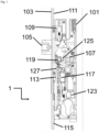
- FIG. 1 shows schematically the lock 1 according to the invention in a top view of a preferred embodiment of the invention.
- the reference numbers used in the claims and the above description are clear here in relation to the specific embodiment.
- What should be emphasized is the arrangement of the latch bolt 105, which according to the invention is guided through the window-like opening 1131 in the second slide 113, which becomes even clearer from the following figures.
- By providing the latch bolt 105 space is created in the lock 1 shown, which has a backset of only 35 mm, for the arrangement of the electric geared motor 117.
- the opening 119 can be seen, which must be kept free of rose fittings for the fastening hole, among other things.
- the protective sleeve 1191 is only indicated in this illustration.
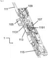
- FIG. 2 The design of the second slide 113 with a window-like opening 1131 formed therein is illustrated by the perspective view of the lock 1 diagonally from the front. The position shown represents the complete locking with the second slider 113 extended downwards and the latch bolt 105 excluded; the first slider 109 is extended downwards, but this cannot be clearly seen in this illustration.
- the representation of the Figure 2 also shows more clearly the protective sleeve 1191 for the opening 119. It can also be seen here how the protective sleeve 1191 serves as a deflection point / pivot point for various elements of the lock 1.
- FIG 3 A schematic detailed representation of the lock 1 according to the invention is shown, which goes into a special embodiment with a spring-loaded locking slide 121 in the first slide 109.
- the locking slide 121 is resiliently mounted out of the first slide 109 in the direction of the latch bolt 105. Its position depends on the position of the upper drive rod 111 and thus on the in Figure 3 Locking not specifically shown. If the upper locking goes into the locking position when the door is closed, then the first slide 109 is moved into a lower end position via the upper drive rod 111 and the spring-loaded locking slide 121 is moved into a recess 1051 of the latch bolt 105 behind the latch head.
- the latch bolt 105 cannot extend a full 20 mm into the strike plate (not shown) when closing the door (e.g. due to a poorly adjusted door or due to warping of the door, so that too much friction between the latch bolt 105 and the strike plate reduces the spring force of the latch bolt 105 is not sufficient to extend the latch bolt 105 a full 20 mm or if there is something in the striking plate recess for the latch bolt 105 that would prevent the latch bolt 105 from being extended), then the locking slide 121 would be rigidly connected to the first slide 109 would come to rest on the latch bolt 105. The upper drive rod 111 with the first slide 109 could not move further into the lower end position and therefore the upper lock could not lock completely.
- the locking slide 105 since the locking slide 105 according to the invention is spring-mounted in the first slide 109, it would dip into the housing of the first slide 109 when resting on the latch bolt 105 and the upper drive rod 111 can move further into the lower end position, so that complete upper locking is guaranteed becomes.
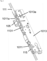
- Figure 4 shows that in Figure 1 Lock 1 according to the invention shown with applied lock case plate 1011 and applied lock case cover 1013. In this form it is used by the user.
- the illustration shows in particular the recess 1011a in the lock case plate 1011 and the recess 1013a in the lock case ceiling 1013, which additionally guide the second slide 113 in the area of the window-like opening 1131.
- the handle / external handle can be coupled in using the electric geared motor 117.
- Each nut half 107a, 107b is separately sprung so that the handle (ie the "door handle") is held horizontally when at rest.
- the inside nut half 107b is taken along via the outside nut half 107a and the latch bolt 105 can be retracted and the door opened.
Landscapes
- Engineering & Computer Science (AREA)
- Structural Engineering (AREA)
- Mechanical Engineering (AREA)
- Lock And Its Accessories (AREA)
Applications Claiming Priority (1)
| Application Number | Priority Date | Filing Date | Title |
|---|---|---|---|
| DE102022124002.9A DE102022124002B3 (de) | 2022-09-19 | 2022-09-19 | Schloss mit elektromechanischer Mehrfachverriegelung |
Publications (1)
| Publication Number | Publication Date |
|---|---|
| EP4343085A1 true EP4343085A1 (fr) | 2024-03-27 |
Family
ID=88094402
Family Applications (1)
| Application Number | Title | Priority Date | Filing Date |
|---|---|---|---|
| EP23020433.1A Pending EP4343085A1 (fr) | 2022-09-19 | 2023-09-18 | Serrure à verrouillage électromécanique à points multiples |
Country Status (2)
| Country | Link |
|---|---|
| EP (1) | EP4343085A1 (fr) |
| DE (1) | DE102022124002B3 (fr) |
Families Citing this family (1)
| Publication number | Priority date | Publication date | Assignee | Title |
|---|---|---|---|---|
| DE102024127884A1 (de) * | 2024-09-26 | 2026-03-26 | Assa Abloy Sicherheitstechnik Gmbh | Schlossvorrichtung für Kindergärten |
Citations (6)
| Publication number | Priority date | Publication date | Assignee | Title |
|---|---|---|---|---|
| US5373716A (en) * | 1992-10-16 | 1994-12-20 | W&F Manufacturing, Inc. | Multipoint lock assembly for a swinging door |
| US6068304A (en) * | 1998-02-05 | 2000-05-30 | Fix Ab | Espagnolette edge bar assembly |
| WO2001059237A2 (fr) * | 2000-02-10 | 2001-08-16 | Sargent Manufacturing Company | Serrure a mortaiser multipoint |
| DE202006004553U1 (de) | 2006-03-20 | 2006-06-08 | Carl Fuhr Gmbh & Co. Kg | Schließanlage für eine Tür o.dgl. |
| GB2496911A (en) * | 2011-11-26 | 2013-05-29 | Trojan Hardware & Design Ltd | Door latch mechanism |
| DE102016011498B3 (de) | 2016-09-25 | 2017-11-30 | SÜD-Metall Schließsysteme Leipzig GmbH | Türschloss |
Family Cites Families (1)
| Publication number | Priority date | Publication date | Assignee | Title |
|---|---|---|---|---|
| US10876324B2 (en) | 2017-01-19 | 2020-12-29 | Endura Products, Llc | Multipoint lock |
-
2022
- 2022-09-19 DE DE102022124002.9A patent/DE102022124002B3/de active Active
-
2023
- 2023-09-18 EP EP23020433.1A patent/EP4343085A1/fr active Pending
Patent Citations (6)
| Publication number | Priority date | Publication date | Assignee | Title |
|---|---|---|---|---|
| US5373716A (en) * | 1992-10-16 | 1994-12-20 | W&F Manufacturing, Inc. | Multipoint lock assembly for a swinging door |
| US6068304A (en) * | 1998-02-05 | 2000-05-30 | Fix Ab | Espagnolette edge bar assembly |
| WO2001059237A2 (fr) * | 2000-02-10 | 2001-08-16 | Sargent Manufacturing Company | Serrure a mortaiser multipoint |
| DE202006004553U1 (de) | 2006-03-20 | 2006-06-08 | Carl Fuhr Gmbh & Co. Kg | Schließanlage für eine Tür o.dgl. |
| GB2496911A (en) * | 2011-11-26 | 2013-05-29 | Trojan Hardware & Design Ltd | Door latch mechanism |
| DE102016011498B3 (de) | 2016-09-25 | 2017-11-30 | SÜD-Metall Schließsysteme Leipzig GmbH | Türschloss |
Also Published As
| Publication number | Publication date |
|---|---|
| DE102022124002B3 (de) | 2023-10-12 |
Similar Documents
| Publication | Publication Date | Title |
|---|---|---|
| DE102006011263B4 (de) | Verriegelungssystem für eine Tür | |
| CH680522A5 (fr) | ||
| DE102017105125A1 (de) | Verriegelungseinheit für eine Schließanlage einer Tür | |
| DE202011108234U1 (de) | Selbstverriegelndes Fallenschloss | |
| DE19604442A1 (de) | Sicherheitsvorrichtung für elektronische Schlösser | |
| DE19730552C1 (de) | Einrichtung zum Entriegeln eines mechanisch selbstverriegelnden Mehrfachschlosses | |
| EP4060147B1 (fr) | Dispositifs d'actionnement pour une serrure, ainsi que systèmes serrures pourvus de tels dispositifs d'actionnement | |
| DE29608862U1 (de) | Schloß, insbesondere Einsteckschloß | |
| DE102022124002B3 (de) | Schloss mit elektromechanischer Mehrfachverriegelung | |
| DE9104553U1 (de) | Mehrriegel-Türschloß | |
| EP1056915A1 (fr) | Serrure | |
| EP3569800B1 (fr) | Serrure, en particulier serrure à pêne de jour | |
| EP2711490B1 (fr) | Dispositif de déplacement d'un corps mobile de manière translatoire et serrure avec un verrou | |
| DE102015000606A1 (de) | Verriegelungsvorrichtung für einen schwenkbar gelagerten Flügel | |
| EP4438836B1 (fr) | Système de fermeture et porte ou fenêtre dotée d'un tel système de fermeture | |
| DE3840183C2 (de) | Beschlag für Fenster oder Türen | |
| DE102016118139A1 (de) | Trennscheibe für Paniknuss | |
| DE10122466A1 (de) | Schloß | |
| EP1739257B1 (fr) | Serrure | |
| CH715020A1 (de) | Schloss, Beschlag, Schliessblech und Schliessvorrichtung für Schiebetüren sowie Schiebetüranlage. | |
| EP2998475B1 (fr) | Levier de jour pour une serrure a battant passif | |
| EP0913550B1 (fr) | Crémone-serrure | |
| EP1724417B1 (fr) | Élément de serrure | |
| EP4089253A1 (fr) | Système de fermeture et porte et fenêtre pourvues du système de fermeture | |
| DE19849798A1 (de) | Auszugsführung mit Verriegelung |
Legal Events
| Date | Code | Title | Description |
|---|---|---|---|
| PUAI | Public reference made under article 153(3) epc to a published international application that has entered the european phase |
Free format text: ORIGINAL CODE: 0009012 |
|
| STAA | Information on the status of an ep patent application or granted ep patent |
Free format text: STATUS: THE APPLICATION HAS BEEN PUBLISHED |
|
| AK | Designated contracting states |
Kind code of ref document: A1 Designated state(s): AL AT BE BG CH CY CZ DE DK EE ES FI FR GB GR HR HU IE IS IT LI LT LU LV MC ME MK MT NL NO PL PT RO RS SE SI SK SM TR |
|
| STAA | Information on the status of an ep patent application or granted ep patent |
Free format text: STATUS: REQUEST FOR EXAMINATION WAS MADE |
|
| 17P | Request for examination filed |
Effective date: 20240326 |
|
| RBV | Designated contracting states (corrected) |
Designated state(s): AL AT BE BG CH CY CZ DE DK EE ES FI FR GB GR HR HU IE IS IT LI LT LU LV MC ME MK MT NL NO PL PT RO RS SE SI SK SM TR |