EP4343091A1 - Dispositif pour identifier une position d'une poignée de véhicule - Google Patents
Dispositif pour identifier une position d'une poignée de véhicule Download PDFInfo
- Publication number
- EP4343091A1 EP4343091A1 EP22196543.7A EP22196543A EP4343091A1 EP 4343091 A1 EP4343091 A1 EP 4343091A1 EP 22196543 A EP22196543 A EP 22196543A EP 4343091 A1 EP4343091 A1 EP 4343091A1
- Authority
- EP
- European Patent Office
- Prior art keywords
- cam
- axis
- handle
- several switch
- around
- Prior art date
- Legal status (The legal status is an assumption and is not a legal conclusion. Google has not performed a legal analysis and makes no representation as to the accuracy of the status listed.)
- Pending
Links
- 230000000295 complement effect Effects 0.000 claims abstract description 4
- 230000005540 biological transmission Effects 0.000 claims description 6
- 101000794560 Arbacia punctulata Calmodulin-beta Proteins 0.000 description 12
- 230000033001 locomotion Effects 0.000 description 3
- 230000004913 activation Effects 0.000 description 2
- 238000001514 detection method Methods 0.000 description 2
- 230000004807 localization Effects 0.000 description 2
- 238000007789 sealing Methods 0.000 description 2
- 238000000605 extraction Methods 0.000 description 1
- 230000007704 transition Effects 0.000 description 1
Images


Classifications
-
- E—FIXED CONSTRUCTIONS
- E05—LOCKS; KEYS; WINDOW OR DOOR FITTINGS; SAFES
- E05B—LOCKS; ACCESSORIES THEREFOR; HANDCUFFS
- E05B85/00—Details of vehicle locks not provided for in groups E05B77/00 - E05B83/00
- E05B85/10—Handles
- E05B85/107—Pop-out handles, e.g. sliding outwardly before rotation
-
- E—FIXED CONSTRUCTIONS
- E05—LOCKS; KEYS; WINDOW OR DOOR FITTINGS; SAFES
- E05B—LOCKS; ACCESSORIES THEREFOR; HANDCUFFS
- E05B81/00—Power-actuated vehicle locks
- E05B81/54—Electrical circuits
- E05B81/64—Monitoring or sensing, e.g. by using switches or sensors
- E05B81/76—Detection of handle operation; Detection of a user approaching a handle; Electrical switching actions performed by door handles
-
- B—PERFORMING OPERATIONS; TRANSPORTING
- B60—VEHICLES IN GENERAL
- B60R—VEHICLES, VEHICLE FITTINGS, OR VEHICLE PARTS, NOT OTHERWISE PROVIDED FOR
- B60R16/00—Electric or fluid circuits specially adapted for vehicles and not otherwise provided for; Arrangement of elements of electric or fluid circuits specially adapted for vehicles and not otherwise provided for
- B60R16/02—Electric or fluid circuits specially adapted for vehicles and not otherwise provided for; Arrangement of elements of electric or fluid circuits specially adapted for vehicles and not otherwise provided for electric constitutive elements
- B60R16/023—Electric or fluid circuits specially adapted for vehicles and not otherwise provided for; Arrangement of elements of electric or fluid circuits specially adapted for vehicles and not otherwise provided for electric constitutive elements for transmission of signals between vehicle parts or subsystems
- B60R16/027—Electric or fluid circuits specially adapted for vehicles and not otherwise provided for; Arrangement of elements of electric or fluid circuits specially adapted for vehicles and not otherwise provided for electric constitutive elements for transmission of signals between vehicle parts or subsystems between relatively movable parts of the vehicle, e.g. between steering wheel and column
Definitions
- the present invention relates to the field of handles for vehicle doors, and in particular to devices for identifying a position of a handle.
- the present invention provides a device for identifying a position of a grip member of a vehicle handle, the device comprising a cam rotatably movable inside the device around an axis, said axis being fixed relative to the grip member, said cam being rotatably secured to a lever, which is rotatably movable around the axis, so that an angular position of the cam around the axis is directly related to an angular position of the lever around the axis, said angular position of the lever being also mechanically related to the position of the grip member, the device further comprising one or several switch(es), said one or several switch(es) being secured to the handle and complementary to a member of the cam, so that the one or several switch(es) is configured to be in electrical contact with the member of the cam when the angular position of the cam is equal to one or more predetermined angular position(s) around the axis.
- the tolerance chain to reach the predetermined angular position is reduced, and the precision is increased, all the more so as a placement of the device in the handle is determined in order to avoid deformations of said device.
- the invention comprises one or more of the following features, alone or in any combination technically compatible.
- the device further comprises a housing member configured to be secured to the handle, the cam and the one or several switch(es) being lodged inside the housing member, the one or several switch(es) being secured to the housing member.
- switches are centralized which has the advantage of focussing accuracy in one element only, i.e. the device, and to optimize the industrialisation flow with one fitting operation, one operation of sealing, and localisation of wire layout.
- the cam and the switch of the device are maintained and protected against the environment, and the device is a standalone device which may be mounted on the handle with proper centering and fixation.
- the member of the cam is a portion of a surface of the cam.
- the one or several switch(es) is protruding from a surface facing the portion of the surface of the cam.
- the member is protruding from a surface of the cam.
- the one or several switch(es) is one or more blades on a printed circuit board.
- the cam is rotatably secured to the lever through a transmission axis which is rigid.
- the cam is rotatably secured to the lever through a transmission axis which is resilient.
- the device further comprises at least one electric wire connected to the one or several switch(es) at one end and configured to provide a signal at another end to an electrical control unit of the vehicle, the signal being representative of the position of the grip member of the vehicle handle of the vehicle.
- the invention provides a vehicle handle comprising a grip member and a device for identifying a position of the grip member according to any one of the embodiments described herein above.
- the invention provides a vehicle comprising a vehicle handle according to the above embodiment.
- fig. 1a represents a position "flush” of the grip member of the flush handle
- fig. 1b represents a position "deployed” of the grip member
- fig. 1c represents a position "open” of the grip member; the transition from one to the other of these successive positions is motorized and e-controlled, i.e. electronically controlled
- fig. 1d represents a backup position corresponding to a backup manual extraction of the grip member of the flush handle.
- the positions of the grip member H are currently recognized by the activation of different switches through the movement of a rod having a specific shape to activate the proper switch.
- the signal of each single switch is sent to the vehicle or to an electronic control unit, which will recognize the handle position based on the signal, and will use this, for example, to stop or activate the actuator.
- the invention consists in replacing this traditional activation of the switches, sliding away from the rod, by a system working in a rotational way, instead of the linear translation motion of the rod. Motion is transferred from a kinematic lever, directly from his axe of rotation; this reduces tolerance chain to reach target position.
- the handle consists of a housing in which at least one lever is arranged and a grip member which can be grasped by a user with his hand in order to open a door.
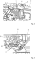
- the device 1 comprises a cam B rotatably movable around an axis X, said axis X being fixed relative to a grip member H of a vehicle handle E; said cam B is rotatably secured to a lever L, which is rotatably movable around the axis X, so that an angular position of the cam B around the axis X is directly related to an angular position of the lever L around the axis X, said angular position of the lever L being also mechanically related to the position of the grip member H.
- the device further comprises one or several switch(es) A, A', said one or several switch(es) A, A' being secured to the handle E, especially to the housing of the handle E; the one or several switch(es) A, A' is configured to be in electrical contact with a complementary member M, M' of the cam B, when the angular position of the cam B is equal to one or more predetermined angular position(s) around the axis X.
- the tolerance chain to reach the predetermined angular position is reduced, and the precision is increased, all the more so as a placement of the device in the handle is determined in order to avoid deformations of said device.
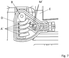
- the device 1 also comprises a housing member D, such as a box, configured to be secured to the handle E, the cam B and the one or several switch(es) A, A' being lodged inside the housing member D, the one or several switch(es) A, A' being secured to the housing member D.
- a housing member D such as a box
- switches A, A' are centralized; this has the advantage of focussing accuracy in one element only, i.e. the device 1, and to optimize the industrialisation flow with one fitting operation, one operation of sealing, and localisation of wire layout.
- the cam B and the switch A, A' of the device 1 are maintained and protected against the environment, and the device 1 is a standalone device 1 which may be mounted on the handle E with proper centering and fixation.
- the member M of the cam B is a portion of a surface of the cam B, as illustrated in figure 4 . More particularly, the one or several switch(es) A is protruding from a surface facing the portion of the surface of the cam B.
- the one or several switch(es) A' is one or more blades A', as illustrated in figure 7 , on a printed circuit board PCB as illustrated in figures 5, 6 and 7 . More particularly, the member M' is protruding from a surface of the cam B, as illustrated in figure 7 .
- the cam B is rotatably secured to the lever L through a transmission axis C which is rigid.
- the transmission axis C which is resilient.
- alignment errors are absorbed, and tension is smoothed.
- the device 1 may further comprise one or more electric wire(s) connected to the one or several switch(es) A, A' at one end and configured to provide a signal at another end to an electrical control unit of the vehicle, the signal being representative of the position of the grip member H of the vehicle handle E of the vehicle.
- the invention also relates to a vehicle handle E comprising a grip member H and a device 1 for identifying a position of the grip member H, according to any one of the embodiments described herein above.
- the invention also relates to a vehicle comprising a vehicle handle according to the embodiment described above.
Landscapes
- Engineering & Computer Science (AREA)
- Mechanical Engineering (AREA)
- Lock And Its Accessories (AREA)
Priority Applications (4)
| Application Number | Priority Date | Filing Date | Title |
|---|---|---|---|
| EP22196543.7A EP4343091A1 (fr) | 2022-09-20 | 2022-09-20 | Dispositif pour identifier une position d'une poignée de véhicule |
| EP23197428.8A EP4343092A1 (fr) | 2022-09-20 | 2023-09-14 | Dispositif pour identifier une position d'une poignée de véhicule |
| CN202311211377.7A CN117738549A (zh) | 2022-09-20 | 2023-09-18 | 用于识别车辆把手位置的装置 |
| US18/469,901 US20240093541A1 (en) | 2022-09-20 | 2023-09-19 | Device for identifying a position of a vehicle handle |
Applications Claiming Priority (1)
| Application Number | Priority Date | Filing Date | Title |
|---|---|---|---|
| EP22196543.7A EP4343091A1 (fr) | 2022-09-20 | 2022-09-20 | Dispositif pour identifier une position d'une poignée de véhicule |
Publications (1)
| Publication Number | Publication Date |
|---|---|
| EP4343091A1 true EP4343091A1 (fr) | 2024-03-27 |
Family
ID=83398166
Family Applications (2)
| Application Number | Title | Priority Date | Filing Date |
|---|---|---|---|
| EP22196543.7A Pending EP4343091A1 (fr) | 2022-09-20 | 2022-09-20 | Dispositif pour identifier une position d'une poignée de véhicule |
| EP23197428.8A Pending EP4343092A1 (fr) | 2022-09-20 | 2023-09-14 | Dispositif pour identifier une position d'une poignée de véhicule |
Family Applications After (1)
| Application Number | Title | Priority Date | Filing Date |
|---|---|---|---|
| EP23197428.8A Pending EP4343092A1 (fr) | 2022-09-20 | 2023-09-14 | Dispositif pour identifier une position d'une poignée de véhicule |
Country Status (3)
| Country | Link |
|---|---|
| US (1) | US20240093541A1 (fr) |
| EP (2) | EP4343091A1 (fr) |
| CN (1) | CN117738549A (fr) |
Citations (3)
| Publication number | Priority date | Publication date | Assignee | Title |
|---|---|---|---|---|
| US20180171686A1 (en) * | 2016-12-20 | 2018-06-21 | Mgi Coutier | Leveled opening control |
| US20190291543A1 (en) * | 2018-03-21 | 2019-09-26 | Akwel Vigo Spain Sl | Opening control device with emergency mechanical unlocking |
| US20220170298A1 (en) * | 2020-11-27 | 2022-06-02 | Illinois Tool Works Inc. | Actuating device for a door lock of a vehicle door |
Family Cites Families (1)
| Publication number | Priority date | Publication date | Assignee | Title |
|---|---|---|---|---|
| ES3004357T3 (en) * | 2021-01-06 | 2025-03-12 | Minebea Accesssolutions Italia S P A | Electronic vehicle handle assembly including a mechanical switch |
-
2022
- 2022-09-20 EP EP22196543.7A patent/EP4343091A1/fr active Pending
-
2023
- 2023-09-14 EP EP23197428.8A patent/EP4343092A1/fr active Pending
- 2023-09-18 CN CN202311211377.7A patent/CN117738549A/zh active Pending
- 2023-09-19 US US18/469,901 patent/US20240093541A1/en active Pending
Patent Citations (3)
| Publication number | Priority date | Publication date | Assignee | Title |
|---|---|---|---|---|
| US20180171686A1 (en) * | 2016-12-20 | 2018-06-21 | Mgi Coutier | Leveled opening control |
| US20190291543A1 (en) * | 2018-03-21 | 2019-09-26 | Akwel Vigo Spain Sl | Opening control device with emergency mechanical unlocking |
| US20220170298A1 (en) * | 2020-11-27 | 2022-06-02 | Illinois Tool Works Inc. | Actuating device for a door lock of a vehicle door |
Also Published As
| Publication number | Publication date |
|---|---|
| CN117738549A (zh) | 2024-03-22 |
| US20240093541A1 (en) | 2024-03-21 |
| EP4343092A1 (fr) | 2024-03-27 |
Similar Documents
| Publication | Publication Date | Title |
|---|---|---|
| US8342583B2 (en) | Vehicle panel control system | |
| EP0883150A3 (fr) | Disjoncteur électrique avec commandes manuelles et à distance | |
| US7532095B2 (en) | Apparatus for remotely actuating a manual actuator of a circuit breaker | |
| CN1167099C (zh) | 带有超前动作辅助开关的旋转操作的保护开关 | |
| EP1873800B1 (fr) | Machine-outil électrique et interrupteur correspondant | |
| EP0982646A2 (fr) | Manette de commande | |
| JP2012500625A (ja) | 少なくとも一方の要素が可動的であるツールの2つの要素の相対位置を決定するため使用できる機器を装備した携帯型電動ツール | |
| EP0462168A1 (fr) | Dispositif d'actionnement electrique d'une serrure. | |
| US10678291B2 (en) | Actuator, in particular, for a motor vehicle | |
| US20180172140A1 (en) | Vehicle shift lever assembly | |
| US9475182B2 (en) | Hand-held power tool with mechanically controlled automatic on and off function | |
| CN108257799B (zh) | 电子开关 | |
| EP3141356B1 (fr) | Ciseaux électriques | |
| EP1752688A1 (fr) | Dispositif de changement de vitesses du type "shift-by-wire" | |
| EP4343091A1 (fr) | Dispositif pour identifier une position d'une poignée de véhicule | |
| EP1128005A2 (fr) | Poignée de porte pour véhicule | |
| EP2067659A2 (fr) | Dispositif à commutateur à levier | |
| JPH05196130A (ja) | トランスミッション制御装置 | |
| EP1842215B1 (fr) | Dispositif de commutation | |
| CN110120326B (zh) | 模块、电气开关和电气开关的开关方法 | |
| CN1094848C (zh) | 杆式开关,特别是用于汽车中的转向柱开关 | |
| EP3149263B1 (fr) | Poignée de portière pour véhicule automobile | |
| US20060005660A1 (en) | Hand lever with integrated controller | |
| EP2875905B1 (fr) | Dispositif de commutation pour outils de jardin | |
| CN216487813U (zh) | 开关装置 |
Legal Events
| Date | Code | Title | Description |
|---|---|---|---|
| PUAI | Public reference made under article 153(3) epc to a published international application that has entered the european phase |
Free format text: ORIGINAL CODE: 0009012 |
|
| STAA | Information on the status of an ep patent application or granted ep patent |
Free format text: STATUS: REQUEST FOR EXAMINATION WAS MADE |
|
| 17P | Request for examination filed |
Effective date: 20220920 |
|
| AK | Designated contracting states |
Kind code of ref document: A1 Designated state(s): AL AT BE BG CH CY CZ DE DK EE ES FI FR GB GR HR HU IE IS IT LI LT LU LV MC MK MT NL NO PL PT RO RS SE SI SK SM TR |