EP4343099B1 - Support d'un élément en forme de plaque - Google Patents
Support d'un élément en forme de plaque Download PDFInfo
- Publication number
- EP4343099B1 EP4343099B1 EP23195610.3A EP23195610A EP4343099B1 EP 4343099 B1 EP4343099 B1 EP 4343099B1 EP 23195610 A EP23195610 A EP 23195610A EP 4343099 B1 EP4343099 B1 EP 4343099B1
- Authority
- EP
- European Patent Office
- Prior art keywords
- plate
- shaped element
- fastening strip
- groove
- fire
- Prior art date
- Legal status (The legal status is an assumption and is not a legal conclusion. Google has not performed a legal analysis and makes no representation as to the accuracy of the status listed.)
- Active
Links
Images


Classifications
-
- E—FIXED CONSTRUCTIONS
- E06—DOORS, WINDOWS, SHUTTERS, OR ROLLER BLINDS IN GENERAL; LADDERS
- E06B—FIXED OR MOVABLE CLOSURES FOR OPENINGS IN BUILDINGS, VEHICLES, FENCES OR LIKE ENCLOSURES IN GENERAL, e.g. DOORS, WINDOWS, BLINDS, GATES
- E06B3/00—Window sashes, door leaves, or like elements for closing wall or like openings; Layout of fixed or moving closures, e.g. windows in wall or like openings; Features of rigidly-mounted outer frames relating to the mounting of wing frames
- E06B3/54—Fixing of glass panes or like plates
- E06B3/5427—Fixing of glass panes or like plates the panes mounted flush with the surrounding frame or with the surrounding panes
-
- E—FIXED CONSTRUCTIONS
- E04—BUILDING
- E04B—GENERAL BUILDING CONSTRUCTIONS; WALLS, e.g. PARTITIONS; ROOFS; FLOORS; CEILINGS; INSULATION OR OTHER PROTECTION OF BUILDINGS
- E04B2/00—Walls, e.g. partitions, for buildings; Wall construction with regard to insulation; Connections specially adapted to walls
- E04B2/74—Removable non-load-bearing partitions; Partitions with a free upper edge
- E04B2/7407—Removable non-load-bearing partitions; Partitions with a free upper edge assembled using frames with infill panels or coverings only; made-up of panels and a support structure incorporating posts
- E04B2/7453—Removable non-load-bearing partitions; Partitions with a free upper edge assembled using frames with infill panels or coverings only; made-up of panels and a support structure incorporating posts with panels and support posts, extending from floor to ceiling
- E04B2/7457—Removable non-load-bearing partitions; Partitions with a free upper edge assembled using frames with infill panels or coverings only; made-up of panels and a support structure incorporating posts with panels and support posts, extending from floor to ceiling with wallboards attached to the outer faces of the posts, parallel to the partition
-
- E—FIXED CONSTRUCTIONS
- E04—BUILDING
- E04B—GENERAL BUILDING CONSTRUCTIONS; WALLS, e.g. PARTITIONS; ROOFS; FLOORS; CEILINGS; INSULATION OR OTHER PROTECTION OF BUILDINGS
- E04B2/00—Walls, e.g. partitions, for buildings; Wall construction with regard to insulation; Connections specially adapted to walls
- E04B2/74—Removable non-load-bearing partitions; Partitions with a free upper edge
- E04B2/82—Removable non-load-bearing partitions; Partitions with a free upper edge characterised by the manner in which edges are connected to the building; Means therefor; Special details of easily-removable partitions as far as related to the connection with other parts of the building
-
- E—FIXED CONSTRUCTIONS
- E06—DOORS, WINDOWS, SHUTTERS, OR ROLLER BLINDS IN GENERAL; LADDERS
- E06B—FIXED OR MOVABLE CLOSURES FOR OPENINGS IN BUILDINGS, VEHICLES, FENCES OR LIKE ENCLOSURES IN GENERAL, e.g. DOORS, WINDOWS, BLINDS, GATES
- E06B3/00—Window sashes, door leaves, or like elements for closing wall or like openings; Layout of fixed or moving closures, e.g. windows in wall or like openings; Features of rigidly-mounted outer frames relating to the mounting of wing frames
- E06B3/54—Fixing of glass panes or like plates
- E06B3/58—Fixing of glass panes or like plates by means of borders, cleats, or the like
- E06B3/62—Fixing of glass panes or like plates by means of borders, cleats, or the like of rubber-like elastic cleats
- E06B3/6202—Fixing of glass panes or like plates by means of borders, cleats, or the like of rubber-like elastic cleats positioned between adjoining panes without separate glazing bar
-
- E—FIXED CONSTRUCTIONS
- E04—BUILDING
- E04B—GENERAL BUILDING CONSTRUCTIONS; WALLS, e.g. PARTITIONS; ROOFS; FLOORS; CEILINGS; INSULATION OR OTHER PROTECTION OF BUILDINGS
- E04B2/00—Walls, e.g. partitions, for buildings; Wall construction with regard to insulation; Connections specially adapted to walls
- E04B2/74—Removable non-load-bearing partitions; Partitions with a free upper edge
- E04B2002/7461—Details of connection of sheet panels to frame or posts
- E04B2002/7475—Details of connection of sheet panels to frame or posts using connectors with claws penetrating the sheet panels
-
- E—FIXED CONSTRUCTIONS
- E04—BUILDING
- E04C—STRUCTURAL ELEMENTS; BUILDING MATERIALS
- E04C2/00—Building elements of relatively thin form for the construction of parts of buildings, e.g. sheet materials, slabs, or panels
- E04C2/54—Slab-like translucent elements
-
- E—FIXED CONSTRUCTIONS
- E06—DOORS, WINDOWS, SHUTTERS, OR ROLLER BLINDS IN GENERAL; LADDERS
- E06B—FIXED OR MOVABLE CLOSURES FOR OPENINGS IN BUILDINGS, VEHICLES, FENCES OR LIKE ENCLOSURES IN GENERAL, e.g. DOORS, WINDOWS, BLINDS, GATES
- E06B1/00—Border constructions of openings in walls, floors, or ceilings; Frames to be rigidly mounted in such openings
- E06B1/62—Tightening or covering joints between the border of openings and the frame or between contiguous frames
- E06B2001/622—Tightening or covering joints between the border of openings and the frame or between contiguous frames especially adapted for door frames; Joint covering devices where the wall surface is parallel to the adjacent door or window frame part
Definitions
- the present invention relates to a system for holding a plate-shaped element and a fastening strip usable therefor.
- glass retainers that are visually imperceptible, i.e., "invisible” from the outside, which are grooved into the wall or frame construction. Such constructions do not require any externally visible glass retaining strips.
- the disadvantages of the above solutions are either the visual impairment caused by components visible from the outside or the increased construction effort, for example due to the provision of a groove in existing walls and the like, as for example in the solution according to the EP 0 452 983 A2 , the solution according to the GB 2 318 144 A , the solution according to the FR 2 581 679 A1 , the solution according to the US 2002/0189172 A1 or the solution according to the US 3,412,510 A given.
- the ES 2 304 900 A1 reveals a wall for fencing and partitioning interior spaces with differently shaped and interacting fastening profiles and strips. The same applies to the US 5,094,052 A .
- the object of the present invention is to provide a solution which eliminates the aforementioned disadvantages and enables the mounting of a plate-shaped element which is visually appealing and yet can be implemented with little effort.
- the present invention is based on the finding that the proposed solution eliminates the need for a conventional external frame with glass retaining strips while still ensuring a sufficiently stable mounting. This allows for maximum optical transparency and eliminates the need for a complex frame construction.
- the plate-shaped element is a laminated glass pane comprising two glass panes spaced apart by a peripheral edge seal, wherein the first groove and the second groove are each formed by an inward offset of the edge seal from the edge of the glass panes.
- the plate-shaped element is an insulating glass pane.
- the plate-shaped element is a fire-resistant pane, and a fire-resistant filling, in particular an intumescent material, is provided in an interior space defined by the edge seal and the glass panes. Due to their high weight, it is desirable for such fire-resistant panes to be able to be installed as quickly as possible, which is achieved by the proposed solution.
- the fire protection pane is designed in such a way that it complies with DIN 4102 or DIN EN 13501.
- a fire protection pane suitable for smoke and/or fire protection purposes, advantageously prevents the passage of fire and/or smoke from one fire compartment or room into another fire compartment or room.
- the fire protection layer between the parallel glass panes is activated, absorbing the heat radiation and forming a highly effective insulating layer.
- the fire protection pane is designed according to the so-called gel technology, in which a fire protection layer arranged between two glass panes, which is activated in the event of a fire, is formed from gel-like materials, in particular from organic polymers.
- the glass panes of laminated glass, insulating glass, or fire-resistant glass each have edge printing in the area exposed at the edge by the recess.
- edge printing can, on the one hand, visually conceal the edge seal between the two glass panes.
- the edge printing can provide protection for the respective glass panes from the engaging, bendable tabs.
- a plate-shaped element for a system according to the invention is proposed, which is formed from building material panels or wooden elements, preferably non-combustible building material panels or fire-resistant wooden elements, as base plates.
- a plate-shaped element advantageously consists of two base plates arranged parallel to one another, which are spaced from one another by means of a spacer arranged between the base plates and offset inward from the edge.
- the spacer is advantageously designed such that it stabilizes the base plates of the non-combustible building material panel or the fire-resistant wooden element in the event of a fire.
- the space formed between the base plates and the spacer in an individual wall element is filled with a filler, preferably a non-combustible filler or an intumescent material.
- a filler preferably a non-combustible filler or an intumescent material.
- panel materials that are grooved at the edge can also be used.
- the fire-resistant wooden element or the base plates of the wooden element are made of solid wood and/or a wood-based material.
- Wood-based materials within the meaning of the present invention are understood to mean, in particular, materials produced by crushing wood and subsequently assembling the structural elements thus obtained. The size and shape of the wood particles determine the type of wood-based material and its properties. Furthermore, the wood particles can be bonded together with or without a binding agent. Wood-based materials within the meaning of the invention include, for example, particleboard, fiberboard, plywood, and/or the like.
- the system according to the invention can be used to create a modular partition wall system, in particular by providing fastening strips with bendable tabs on regularly spaced metal or wooden profiles. Plate-shaped elements are then provided between two such profiles. In this way, for example, a partition wall for forming a fire compartment in rooms of buildings can be created relatively easily.
- the structural elements, i.e. the plate-shaped elements, of such a partition wall system can be removed from the profiles without causing damage and are therefore reusable or replaceable.
- the grooved plate elements can also be connected to one another laterally using the bendable tab, advantageously allowing the creation of virtually infinite wall elements.
- the first and second fastening strips each have at least two holes, by means of which the respective fastening strip can be arranged on the wall, floor or ceiling.
- the fastening strips can be glued to the wall, floor or ceiling.
- the fastening strip has a hole on both sides, spaced from each of the bendable tabs. This ensures that the fastening strip fastened by means of screws is held securely even when the bendable tabs are folded out and, in particular, prevents bending of the fastening strip due to bending of the tabs.
- sheet metal in particular sheet steel, is provided as the material for the first and second fastening strips. This material allows for easy bending of the tabs while still ensuring sufficient stability.
- a bendable tab is constructed in several parts and has at least two independently bendable components. This allows plate-shaped elements with grooves of different widths to be accommodated despite using only one type of fastening strip.
- the system comprises a sealant arranged between the wall, floor, ceiling, or a panel-shaped element and the first side of the panel-shaped element and enclosing the first fastening strip, as well as a sealant arranged between the wall, floor, ceiling, or a panel-shaped element and the second side of the panel-shaped element and enclosing the second fastening strip.
- sealants fill the remaining cavity between the wall, floor, ceiling, or the panel-shaped element and the panel-shaped element and can, for example, ensure an airtight seal, which is particularly relevant in the event of a fire.
- the sealing means may preferably be or contain a fire dirt material or an intumescent material.
- the system further comprises a further fastening strip which can be arranged on a wall, floor, ceiling, or a plate-shaped element and has a plurality of further bendable tabs, wherein the plurality of further bendable tabs can be brought into engagement with a further groove of the plate-shaped element which is arranged adjacent to the first groove and the second groove.
- a further fastening strip which can be arranged on a wall, floor, ceiling, or a plate-shaped element and has a plurality of further bendable tabs, wherein the plurality of further bendable tabs can be brought into engagement with a further groove of the plate-shaped element which is arranged adjacent to the first groove and the second groove.
- the present solution further provides a fastening strip comprising a plurality of spaced-apart, bendable tabs and at least two holes, by means of which the fastening strip can be arranged on a wall, floor, ceiling or a plate-shaped element.
- the fastening strip is provided on both sides has a hole spaced apart from each of the extendable tabs. This ensures that the fastening strip, which is attached by screws, is held securely even when the extendable tabs are folded out, and in particular prevents the fastening strip from bending due to the tabs being bent out.
- the material for the fastening strip is sheet metal, aluminum or composite material, in particular sheet steel.
- the material thickness of the fastening strip is in the range of 0.9 mm to 1.1 mm, preferably 1.0 mm.
- the distance between two holes in the mounting strip is 80 to 220 mm. Note: This is variable.
- the width of the fastening strip is in the range of 10 mm to 60 mm, preferably 20 mm.
- the width of the bendable tab is in the range of 11 mm to 13 mm, preferably 11 mm.
- a total length of the strip is provided in the range of 3000 mm to 6000 mm.
- Another advantageous embodiment provides for the production of the fastening strip as an endless strip, which can advantageously be cut to length on site.
- a clearance of a drill hole to a bendable tab is provided in a range of 15 mm to 25 mm, preferably 20 mm. This ensures that the fastening strip is held securely even when the bendable tabs are unfolded and, in particular, prevents the fastening strip from bending due to the tabs being bent.
- At least one bendable tab of the fastening strip is formed in several parts and has at least two independently bendable components.
- the bendable tab can have the contour of a semicircle, a triangle or a rectangle at the end.
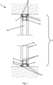
- Fig. 1 shows in a sectional view an embodiment of a system 1 according to the invention for holding a plate-shaped element 2, which in the present case is designed as a fire protection pane.
- the system 1 comprises a first fastening strip 3 which can be arranged on the wall, floor or ceiling and a plurality of first bendable tabs 4 (not visible in Fig. 1 ). Depending on the perspective, the first fastening strip 3 is arranged on a ceiling or on a side wall.
- the system 1 comprises a second fastening strip 3, which is arranged opposite the first fastening strip 3 on the wall, ceiling, or floor.
- the second fastening strip 5 has a plurality of second bendable tabs 6.
- the second fastening strip 5 is arranged on a floor or on another lateral wall.
- the plate-shaped element 2 is provided, which has a first groove 7 provided on a first side and a second groove 8 provided on a second side.
- the plate-shaped element 2 is in this case a laminated glass pane in the form of a fire protection pane having two by means of a circumferential Edge seal 9 spaced-apart glass panes 10/11, wherein the first groove 7 and the second groove 8 are each formed by an inward offset of the edge seal 9 from the edge of the glass panes 10/11.
- a fire protection filling 15 in the form of an intumescent material is introduced into the space defined by the edge seal 9 and the glass panes 10/11.
- the fastening strips 3/5 are arranged in an area which, due to the offset, forms a free space into which the tabs 4/6 can be bent, so that the laminated glass pane is locked accordingly.
- the plurality of first bendable tabs 4 can be brought into engagement with the first groove 7 and the plurality of second bendable tabs 6 can be brought into engagement with the second groove 8.
- the glass panes 10/11 of the laminated glass pane each have an edge print 12 in the area exposed at the edge by the recess. This can be used to prevent damage caused by the tabs 4/6 being folded out or bent out.
- the tab is visually concealed by the edge print.
- the bendable tabs 4/6 of the fastening strip 3/5 are provided with holes in the fastening strip at a distance from each other on both sides. This ensures that the fastening strip, which is fastened by screws, is held securely even when the bendable tabs are folded out and, in particular, prevents bending of the fastening strip due to bending of the tabs.
- a sealing means 14 is arranged between the wall (or ceiling) and the first side of the plate-shaped element 2, which sealing means encloses the first fastening strip 3. Furthermore, a sealing means 14 is also arranged between the wall (or floor) of the second side of the plate-shaped element 2, which sealing means encloses the second fastening strip 5.
- Fig. 2a/2b shows in a perspective view an embodiment of a fastening strip 3/5 according to the invention comprising a tab 4/6 in the initial state ( Fig. 2a ) or in the bent-out state ( Fig. 2b ).
- a fastening strip 3/5 has at least two holes 13, by means of which the fastening strip 3/5 can be arranged on the wall, floor, or ceiling.
- An alternating arrangement of tabs 4/6 and hole 13 is advantageous, to ensure a fixed arrangement of the mounting strip 3/5 on the wall, floor or ceiling.
- a mounting strip 3/5 is provided with flexible tabs 4/6.
- One mounting strip 3/5 is screwed onto a wall (or a frame) on the left and right, for example, in the axis of the panel-shaped element 2.
- the panel-shaped element 2 is then adjusted and aligned.
- sealants 14 for example, silicone-acrylic PU sealant, mineral wool, intumescent building materials, or mineral building materials, depending on the requirements.
- the presented solution is advantageous because it achieves a structurally simple mechanical fastening without additional bonding, no subsequent installation of a glass retaining strip is required, the fastening strip 3/5 with bending tab 4/6 can be prefabricated in infinite length, installation on any type of wall or masonry is possible and use is possible for any type of grooved panel material.
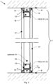
- the embodiment according to Fig. 3 shows a laminated glass pane or fire protection pane as a plate-shaped element 2 arranged between floor B and ceiling D using the system 1 according to the invention.
- the laminated glass pane has two glass panes 17 which are spaced apart from one another by a spacer 16.
- the spacer 16 is offset inwards so that a groove 7 or 8 is formed in the edge of the laminated glass pane.
- the fastening strip marked 18 with bent-out tabs engages in the groove 7 or 8, i.e. either the fastening strip 3 with bent-out tabs 4 or the fastening strip 5 with bent-out tabs 6.
- the panes 17 have an edge printing in their edge region, which visually conceals the spacer 16 as well as the fastening strip marked 18 with bent-out tabs.
- a fire protection pane as a plate-shaped element
- the space between the glass panes 17 and the The space formed by spacers 16 is filled with a fire protection material or at least one fire protection layer.
- the cavity between floor B or ceiling D, the laminated glass pane or the fire protection pane as a plate-shaped element 2, and the fastening strips 3 or 5 is sealed with a sealant 14.
- the embodiment according to Fig. 4 shows a building material panel or a wooden element made of wood-based materials as a panel-shaped element 2 arranged between floor B and ceiling D using the system 1 according to the invention.
- the building material panel or the wooden element made of wood-based materials has a groove 7 or 8 in the edge area.
- the fastening strip marked 18 with bent-out tabs engages in the groove 7 or 8, i.e. either the fastening strip 3 with bent-out tabs 4 or the fastening strip 5 with bent-out tabs 6.
- the cavity between floor B or ceiling D, building material panel or wooden element made of wood-based materials and the fastening strips 3 or 5 is sealed with a sealant 14.
- the embodiment according to Fig. 5 shows a laminated glass pane or fire protection pane as a plate-shaped element 2 arranged with the system 1 according to the invention on a plate-shaped element 2, in this case formed from a building material panel or a wooden element made of wood-based material.
- the laminated glass pane has two panes 17 made of glass, which are spaced apart from one another by a spacer 16.
- the spacer 16 is offset inwards so that a groove 7 or 8 is formed in the edge area of the laminated glass pane.
- the fastening strip marked 18 with bent-out tabs engages in the groove 7 or 8, i.e. either the fastening strip 3 with bent-out tabs 4 or the fastening strip 5 with bent-out tabs 6.
- the panes 17 have an edge printing in their edge region, which visually conceals the spacer 16 as well as the fastening strip marked 18 with bent-out tabs.
- the space formed between the glass panes 17 and the spacer 16 is provided with a filling of a fire protection material or at least one fire protection layer.
- the cavity between the plate-shaped element 2 formed from a building board or a wooden element made of wood-based material, the laminated glass pane or the fire protection pane as a plate-shaped element 2 and the fastening strips 3 and 5 is provided with a Sealant 14.
- the plate-shaped element 2 formed from a building material panel or a wooden element made of wood-based material and the laminated glass pane or fire protection pane 2 having a groove 7 or 8 in the edge region are essentially perpendicular to one another.
- the embodiment according to Fig. 6 shows a building material panel or a wooden element made of wood materials as a panel-shaped element 2 arranged with the system 1 according to the invention on a panel-shaped element 2, in this case formed from a building material panel or a wooden element made of wood-based material.
- the building material panel or the wooden element made of wood materials has a groove 7 or 8 in the edge area.
- the fastening strip marked 18 with bent-out tabs engages in the groove 7 or 8, i.e. either the fastening strip 3 with bent-out tabs 4 or the fastening strip 5 with bent-out tabs 6.
- the hollow space between the panel-shaped element 2 formed from a building material panel or a wooden element made of wood-based material, the building material panel or the wooden element made of wood materials as a panel-shaped element 2 and the fastening strips 3 or 5 is sealed with a sealant 14.
- the plate-shaped element 2 formed from a building material panel or a wooden element made of wood-based material and the plate-shaped element 2 formed from a building material panel or a wooden element made of wood-based material and having a groove 7 or 8 in the edge region are essentially perpendicular to one another.
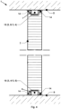
- the embodiment according to Fig. 7 shows a laminated glass pane or fire protection pane as a plate-shaped element 2 arranged with the system 1 according to the invention on a plate-shaped element 2, in this case formed from a building material panel or a wooden element made of wood-based material.
- the laminated glass pane has two panes 17 made of glass, which are spaced apart from one another by a spacer 16.
- the spacer 16 is offset inwards, so that a groove 7 or 8 is formed in the edge area of the laminated glass pane.
- the fastening strip marked 18 with bent-out tabs engages in the groove 7 or 8, i.e. either the fastening strip 3 with bent-out tabs 4 or the fastening strip 5 with bent-out tabs 6.
- the panes 17 have an edge printing in their edge area, which visually conceals the spacer 16 as well as the fastening strip with bent-out tabs marked 18.
- a fire protection pane as a plate-shaped element
- the space formed between the glass panes 17 and the spacer 16 is filled with a fire protection material or at least one fire protection layer.
- the cavity between the plate-shaped element 2 formed from a building board or a wooden element made of wood-based material, the laminated glass pane or the fire protection pane as a plate-shaped element 2, and the fastening strips 3 or 5 is sealed with a sealant 14.
- the plate-shaped element 2 formed from a building board or a wooden element made of wood-based material and the laminated glass pane or fire protection pane 2 having a groove 7 or 8 in the edge region are essentially aligned next to one another, so that the plate-shaped elements 2 are arranged narrow side to narrow side.
- the embodiment according to Fig. 8 shows a building material panel or a wooden element made of wood materials as a panel-shaped element 2 arranged with the system 1 according to the invention on a panel-shaped element 2, in this case formed from a building material panel or a wooden element made of wood-based material.
- the building material panel or the wooden element made of wood materials has a groove 7 or 8 in the edge area.
- the fastening strip marked 18 with bent-out tabs engages in the groove 7 or 8, i.e. either the fastening strip 3 with bent-out tabs 4 or the fastening strip 5 with bent-out tabs 6.
- the hollow space between the panel-shaped element 2 formed from a building material panel or a wooden element made of wood-based material, the building material panel or the wooden element made of wood materials as a panel-shaped element 2 and the fastening strips 3 or 5 is sealed with a sealant 14.
- the plate-shaped element 2 formed from a building material panel or a wooden element made of wood-based material and the plate-shaped element 2 formed from a building material panel or a wooden element made of wood-based material and having a groove 7 or 8 in the edge region are essentially aligned next to one another, so that the plate-shaped elements 2 are arranged narrow side to narrow side.
Landscapes
- Engineering & Computer Science (AREA)
- Civil Engineering (AREA)
- Structural Engineering (AREA)
- Architecture (AREA)
- Physics & Mathematics (AREA)
- Electromagnetism (AREA)
- Securing Of Glass Panes Or The Like (AREA)
- Building Environments (AREA)
Claims (17)
- Système (1), comprenant:une première latte de fixation (3) pouvant être disposée sur un mur, un sol, un plafond ou des éléments (2) en forme de plaques, présentant une pluralité de premières languettes (4) pouvant être déviées,une deuxième latte de fixation (5) pouvant être disposée sur un mur, un plafond ou un sol en face de la première latte de fixation (3) et présentant une pluralité de deuxièmes languettes (6) pouvant être pliées, etun élément en forme de plaque (2) sans cadre périphérique extérieur, comprenant une première rainure (7) prévue sur un premier côté et une deuxième rainure (8) prévue sur un deuxième côté, le deuxième côté étant opposé au premier côté,dans lequel la pluralité de premières languettes fléchissables (4) peuvent être engagées dans la première rainure (7) de l'élément en forme de plaque (2) et la pluralité de secondes languettes fléchissables (6) peuvent être engagées dans la seconde rainure (8) de l'élément en forme de plaque (2).
- Système (1) selon la revendication 1, dans lequel il est prévu comme élément en forme de plaque (2) un vitrage feuilleté présentant deux plaques de verre (10, 11) espacées au moyen d'un joint périphérique (9), la première rainure (7) de l'élément en forme de plaque (2) et la deuxième rainure (8) de l'élément en forme de plaque (2) étant formées chacune par un décalage vers l'arrière du joint périphérique (9) par rapport au bord des plaques de verre (10, 11).
- Système (1) selon la revendication 1 ou la revendication 2, dans lequel l'élément en forme de plaque (2) est un vitrage isolant.
- Système (1) selon la revendication 2 ou selon les revendications 2 et 3, dans lequel l'élément en forme de plaque (2) est une vitre coupe-feu et un remplissage coupe-feu (15), en particulier un matériau intumescent, est prévu dans un espace intérieur défini par le joint périphérique (9) et les vitres (10, 11).
- Système (1) selon l'une des revendications 2 à 4, dans lequel les feuilles de verre (10, 11) du vitrage feuilleté, du vitrage isolant ou du vitrage coupe-feu présentent chacune une impression de bord (12) dans la zone dégagée sur le bord par le retrait du joint périphérique (9) par rapport au bord des feuilles de verre (10, 11).
- Système (1) selon la revendication 1, dans lequel un élément en forme de plaque (2) est formé de plaques de matériau de construction ou d'éléments en bois, de préférence de plaques de matériau de construction incombustibles ou d'éléments en bois ignifuges, en tant que plaques de base, l'élément en forme de plaque (2) étant constitué de deux plaques de base disposées parallèlement l'une à l'autre, qui sont espacées l'une de l'autre au moyen d'une entretoise disposée entre les plaques de base et décalée vers l'intérieur à partir du bord.
- Système (1) selon la revendication 6, dans lequel l'entretoise est conçue de telle sorte qu'elle stabilise les plaques de base du panneau de matériau de construction incombustible ou les plaques de base de l'élément en bois réfractaire en cas d'incendie.
- Système (1) selon la revendication 6 ou la revendication 7, dans lequel l'espace intermédiaire d'un élément en forme de plaque (2) formé par les plaques de base et l'entretoise est rempli d'un matériau de remplissage, de préférence un matériau de remplissage incombustible ou un matériau intumescent en cas d'incendie.
- Système (1) selon l'une quelconque des revendications 6 à 8, dans lequel l'élément en bois réfractaire ou les plaques de base de l'élément en bois est ou sont en bois massif et/ou en un matériau à base de bois.
- Système (1) selon l'une des revendications 6 à 9, dans lequel on utilise comme élément en forme de plaque (2) des matériaux de plaque rainurés sur le bord.
- Système (1) selon l'une des revendications 1 à 10, dans lequel la première et la deuxième latte de fixation (3, 5) présentent chacune au moins deux perçages (13) au moyen desquels la latte de fixation respective (3, 5) peut être disposée sur le mur, le sol ou le plafond.
- Système (1) selon l'une des revendications 1 à 11, dans lequel il est prévu comme matériau pour la première et la deuxième latte de fixation (3, 5) une tôle, en particulier une tôle d'acier.
- Système selon l'une quelconque des revendications 1 à 12, dans lequel une languette pliable est réalisée en plusieurs parties et comporte au moins deux éléments constitutifs pouvant être pliés indépendamment l'un de l'autre.
- Système (1) selon l'une des revendications 1 à 13, comprenant en outre un moyen d'étanchéité (14) disposé entre le mur, le plafond ou le sol et le premier côté de l'élément en forme de plaque (2) et entourant la première latte de fixation (3), ainsi qu'un moyen d'étanchéité (14) disposé entre le mur, le sol ou le plafond et le deuxième côté de l'élément en forme de plaque (2) et entourant la deuxième latte de fixation (5).
- Système (1) selon l'une quelconque des revendications 1 à 14, comprenant en outre au moins une autre latte de fixation (3, 5) pouvant être disposée sur un mur, un sol, un plafond ou des éléments en forme de plaque (2), présentant une pluralité d'autres languettes (4, 6) pouvant être pliées, la pluralité d'autres languettes (4, 6) pouvant être pliées pouvant être mises en prise avec une autre rainure de l'élément en forme de plaque (2), qui est disposée de manière adjacente à la première rainure et à la deuxième rainure.
- Système (1) selon l'une des revendications 1 à 15, dans lequel une languette (4, 6) pliable de la latte de fixation (3, 5) présente à son extrémité le contour d'un demi-cercle, ou une languette (4, 6) pliable présente à son extrémité le contour d'un triangle, ou une languette (4, 6) pliable présente à son extrémité le contour d'un rectangle.
- Système (1) selon l'une quelconque des revendications 1 à 16, dans lequel celui-ci forme une cloison, en particulier pour former un compartiment coupe-feu dans des pièces de bâtiments, dans lequel des lattes de fixation (3, 5) avec des languettes pliables (4, 6) sont prévues sur des profilés en métal ou en bois disposés à intervalles réguliers et des éléments en forme de plaques (2) sont prévus entre deux profilés de ce type.
Applications Claiming Priority (1)
| Application Number | Priority Date | Filing Date | Title |
|---|---|---|---|
| DE202022105306.5U DE202022105306U1 (de) | 2022-09-21 | 2022-09-21 | Halterung eines plattenförmigen Elements |
Publications (3)
| Publication Number | Publication Date |
|---|---|
| EP4343099A1 EP4343099A1 (fr) | 2024-03-27 |
| EP4343099C0 EP4343099C0 (fr) | 2025-06-18 |
| EP4343099B1 true EP4343099B1 (fr) | 2025-06-18 |
Family
ID=87933673
Family Applications (1)
| Application Number | Title | Priority Date | Filing Date |
|---|---|---|---|
| EP23195610.3A Active EP4343099B1 (fr) | 2022-09-21 | 2023-09-06 | Support d'un élément en forme de plaque |
Country Status (2)
| Country | Link |
|---|---|
| EP (1) | EP4343099B1 (fr) |
| DE (1) | DE202022105306U1 (fr) |
Family Cites Families (12)
| Publication number | Priority date | Publication date | Assignee | Title |
|---|---|---|---|---|
| DE1708003B1 (de) * | 1965-12-10 | 1971-12-09 | Transglas Ag | Glaswand mit einer Mehrzahl von im Querschnitt U-foermigen,etwa wandhohen Glaselementen |
| DE2532172C3 (de) * | 1975-07-18 | 1979-02-15 | Glas- Und Spiegel-Manufactur Ag, 4650 Gelsenkirchen | Aus U-förmigen Glasprofilen zusammengesetzte Wand mit in die Wandfläche eingesetzten Rahmenelementen |
| FR2581679B1 (fr) * | 1985-05-10 | 1988-03-04 | Louis Andre | Element modulaire pour construction de cloison |
| EP0452983A3 (en) * | 1987-03-13 | 1992-04-22 | Thomas John Wood | Fastening device |
| US5094052A (en) * | 1987-04-21 | 1992-03-10 | Edgar Gudmundsson | Building wall construction |
| GB2318144B (en) * | 1996-10-08 | 2000-02-16 | Anglian Windows Ltd | Resilient clips for securing replacement window and door assemblies |
| DE10124733A1 (de) * | 2001-05-21 | 2002-11-28 | Geze Glas Design Gmbh | Vorrichtung zur Höhenanpassung einer Trennwand |
| US6647691B2 (en) * | 2001-06-15 | 2003-11-18 | Duane William Becker | Track arrangement for supporting wall studs; method; and, wall framework assembly |
| US6843035B1 (en) * | 2003-04-08 | 2005-01-18 | William J. Glynn | Track component for fabricating a deflection wall |
| ES2304900B1 (es) * | 2008-04-09 | 2009-10-13 | Antonio Paredes Davila | Pared para cerramientos y division de espacios interiores. |
| DK2649251T3 (da) * | 2010-12-06 | 2021-01-04 | Zak It Systems Gmbh | Yderskinne til en base til en vægpladeafdækning |
| US20180195282A1 (en) * | 2015-01-27 | 2018-07-12 | California Expanded Metal Products Company | Tab track fire-rated wall assembly with dynamic movement |
-
2022
- 2022-09-21 DE DE202022105306.5U patent/DE202022105306U1/de active Active
-
2023
- 2023-09-06 EP EP23195610.3A patent/EP4343099B1/fr active Active
Also Published As
| Publication number | Publication date |
|---|---|
| EP4343099A1 (fr) | 2024-03-27 |
| DE202022105306U1 (de) | 2024-01-02 |
| EP4343099C0 (fr) | 2025-06-18 |
Similar Documents
| Publication | Publication Date | Title |
|---|---|---|
| EP3060725B1 (fr) | Composite anti-effraction et structure de mur porteur, de toit ou de plafond | |
| EP2307629A2 (fr) | Paroi de séparation constituée d'éléments de paroi transparents | |
| EP2405093B1 (fr) | Verrière ignifuge modulaire | |
| EP4343099B1 (fr) | Support d'un élément en forme de plaque | |
| EP0947638A2 (fr) | Panneau d'isolation pour façades extérieures de maisons | |
| AT507059B1 (de) | Wandverbund | |
| EP0902154B1 (fr) | Vitrage pare-feu | |
| EP3085873B1 (fr) | Panneau a effet | |
| CH674541A5 (fr) | ||
| EP0861963B1 (fr) | Vitrage pare-feu | |
| AT398229B (de) | Schachteinrichtung mit einem nach unten offenen aufnahmeschacht zur aufnahme eines rolladens, einer jalousie oder dergleichen | |
| DE10253417B4 (de) | Verbindungssystem für Wandelemente einer Trennwand | |
| EP1076746B1 (fr) | Element de fixation pour fixer des materiaux plats et procede de fixation desdits materiaux | |
| EP3170962A1 (fr) | Vitrage anti-feu comprenant des vitres décalées | |
| CH707540A2 (de) | Tragendes Glaswandelement für leichte Holzbauten. | |
| AT527214B1 (de) | Platte für den Trockenausbau | |
| EP4001531B1 (fr) | Ensemble pour une cabane à outils | |
| EP1574632B1 (fr) | Mur en construction sèche | |
| WO2011144409A1 (fr) | Paroi anti-effraction | |
| DE202023104429U1 (de) | Brandabschottung für Leitungen in Gebäuden | |
| DE102008040296B4 (de) | Pfosten für eine Pfosten-Riegel- oder Elementkonstruktion, Verfahren zu dessen Herstellung und Pfosten-Riegel- oder Elementkonstruktion, die einen Pfosten aufweist | |
| DE102017108587A1 (de) | Verbundfenster sowie Kombi-Glashalter hierfür | |
| EP0558457A1 (fr) | Elément d'isolation acoustique pour décoration | |
| DE29807809U1 (de) | Rahmenelement für eine Brandschutzverglasung | |
| DE102016112021A1 (de) | Verglasungssystem |
Legal Events
| Date | Code | Title | Description |
|---|---|---|---|
| PUAI | Public reference made under article 153(3) epc to a published international application that has entered the european phase |
Free format text: ORIGINAL CODE: 0009012 |
|
| STAA | Information on the status of an ep patent application or granted ep patent |
Free format text: STATUS: THE APPLICATION HAS BEEN PUBLISHED |
|
| AK | Designated contracting states |
Kind code of ref document: A1 Designated state(s): AL AT BE BG CH CY CZ DE DK EE ES FI FR GB GR HR HU IE IS IT LI LT LU LV MC ME MK MT NL NO PL PT RO RS SE SI SK SM TR |
|
| STAA | Information on the status of an ep patent application or granted ep patent |
Free format text: STATUS: REQUEST FOR EXAMINATION WAS MADE |
|
| 17P | Request for examination filed |
Effective date: 20240725 |
|
| RBV | Designated contracting states (corrected) |
Designated state(s): AL AT BE BG CH CY CZ DE DK EE ES FI FR GB GR HR HU IE IS IT LI LT LU LV MC ME MK MT NL NO PL PT RO RS SE SI SK SM TR |
|
| RIC1 | Information provided on ipc code assigned before grant |
Ipc: E06B 1/62 20060101ALI20241219BHEP Ipc: E06B 3/62 20060101ALI20241219BHEP Ipc: E06B 3/663 20060101ALI20241219BHEP Ipc: E06B 3/66 20060101ALI20241219BHEP Ipc: E06B 3/58 20060101ALI20241219BHEP Ipc: E04C 2/54 20060101ALI20241219BHEP Ipc: E04B 2/74 20060101ALI20241219BHEP Ipc: E04B 2/82 20060101ALI20241219BHEP Ipc: E06B 3/60 20060101ALI20241219BHEP Ipc: E06B 3/54 20060101AFI20241219BHEP |
|
| GRAP | Despatch of communication of intention to grant a patent |
Free format text: ORIGINAL CODE: EPIDOSNIGR1 |
|
| STAA | Information on the status of an ep patent application or granted ep patent |
Free format text: STATUS: GRANT OF PATENT IS INTENDED |
|
| INTG | Intention to grant announced |
Effective date: 20250317 |
|
| GRAS | Grant fee paid |
Free format text: ORIGINAL CODE: EPIDOSNIGR3 |
|
| GRAA | (expected) grant |
Free format text: ORIGINAL CODE: 0009210 |
|
| STAA | Information on the status of an ep patent application or granted ep patent |
Free format text: STATUS: THE PATENT HAS BEEN GRANTED |
|
| AK | Designated contracting states |
Kind code of ref document: B1 Designated state(s): AL AT BE BG CH CY CZ DE DK EE ES FI FR GB GR HR HU IE IS IT LI LT LU LV MC ME MK MT NL NO PL PT RO RS SE SI SK SM TR |
|
| REG | Reference to a national code |
Ref country code: GB Ref legal event code: FG4D Free format text: NOT ENGLISH |
|
| REG | Reference to a national code |
Ref country code: CH Ref legal event code: EP |
|
| REG | Reference to a national code |
Ref country code: DE Ref legal event code: R096 Ref document number: 502023001178 Country of ref document: DE |
|
| REG | Reference to a national code |
Ref country code: CH Ref legal event code: EP |
|
| REG | Reference to a national code |
Ref country code: IE Ref legal event code: FG4D Free format text: LANGUAGE OF EP DOCUMENT: GERMAN |
|
| U01 | Request for unitary effect filed |
Effective date: 20250618 |
|
| U07 | Unitary effect registered |
Designated state(s): AT BE BG DE DK EE FI FR IT LT LU LV MT NL PT RO SE SI Effective date: 20250627 |
|
| PG25 | Lapsed in a contracting state [announced via postgrant information from national office to epo] |
Ref country code: NO Free format text: LAPSE BECAUSE OF FAILURE TO SUBMIT A TRANSLATION OF THE DESCRIPTION OR TO PAY THE FEE WITHIN THE PRESCRIBED TIME-LIMIT Effective date: 20250918 Ref country code: GR Free format text: LAPSE BECAUSE OF FAILURE TO SUBMIT A TRANSLATION OF THE DESCRIPTION OR TO PAY THE FEE WITHIN THE PRESCRIBED TIME-LIMIT Effective date: 20250919 |
|
| PG25 | Lapsed in a contracting state [announced via postgrant information from national office to epo] |
Ref country code: HR Free format text: LAPSE BECAUSE OF FAILURE TO SUBMIT A TRANSLATION OF THE DESCRIPTION OR TO PAY THE FEE WITHIN THE PRESCRIBED TIME-LIMIT Effective date: 20250618 |
|
| PG25 | Lapsed in a contracting state [announced via postgrant information from national office to epo] |
Ref country code: RS Free format text: LAPSE BECAUSE OF FAILURE TO SUBMIT A TRANSLATION OF THE DESCRIPTION OR TO PAY THE FEE WITHIN THE PRESCRIBED TIME-LIMIT Effective date: 20250918 |
|
| U20 | Renewal fee for the european patent with unitary effect paid |
Year of fee payment: 3 Effective date: 20250924 |
|
| PG25 | Lapsed in a contracting state [announced via postgrant information from national office to epo] |
Ref country code: IS Free format text: LAPSE BECAUSE OF FAILURE TO SUBMIT A TRANSLATION OF THE DESCRIPTION OR TO PAY THE FEE WITHIN THE PRESCRIBED TIME-LIMIT Effective date: 20251018 |
|
| PG25 | Lapsed in a contracting state [announced via postgrant information from national office to epo] |
Ref country code: SM Free format text: LAPSE BECAUSE OF FAILURE TO SUBMIT A TRANSLATION OF THE DESCRIPTION OR TO PAY THE FEE WITHIN THE PRESCRIBED TIME-LIMIT Effective date: 20250618 |
|
| PG25 | Lapsed in a contracting state [announced via postgrant information from national office to epo] |
Ref country code: CZ Free format text: LAPSE BECAUSE OF FAILURE TO SUBMIT A TRANSLATION OF THE DESCRIPTION OR TO PAY THE FEE WITHIN THE PRESCRIBED TIME-LIMIT Effective date: 20250618 |
|
| PG25 | Lapsed in a contracting state [announced via postgrant information from national office to epo] |
Ref country code: PL Free format text: LAPSE BECAUSE OF FAILURE TO SUBMIT A TRANSLATION OF THE DESCRIPTION OR TO PAY THE FEE WITHIN THE PRESCRIBED TIME-LIMIT Effective date: 20250618 |
|
| PG25 | Lapsed in a contracting state [announced via postgrant information from national office to epo] |
Ref country code: SK Free format text: LAPSE BECAUSE OF FAILURE TO SUBMIT A TRANSLATION OF THE DESCRIPTION OR TO PAY THE FEE WITHIN THE PRESCRIBED TIME-LIMIT Effective date: 20250618 |
|
| PG25 | Lapsed in a contracting state [announced via postgrant information from national office to epo] |
Ref country code: ES Free format text: LAPSE BECAUSE OF FAILURE TO SUBMIT A TRANSLATION OF THE DESCRIPTION OR TO PAY THE FEE WITHIN THE PRESCRIBED TIME-LIMIT Effective date: 20250618 |
|
| PLBE | No opposition filed within time limit |
Free format text: ORIGINAL CODE: 0009261 |
|
| STAA | Information on the status of an ep patent application or granted ep patent |
Free format text: STATUS: NO OPPOSITION FILED WITHIN TIME LIMIT |