EP4343178A1 - Joint d'étanchéité - Google Patents
Joint d'étanchéité Download PDFInfo
- Publication number
- EP4343178A1 EP4343178A1 EP22804510.0A EP22804510A EP4343178A1 EP 4343178 A1 EP4343178 A1 EP 4343178A1 EP 22804510 A EP22804510 A EP 22804510A EP 4343178 A1 EP4343178 A1 EP 4343178A1
- Authority
- EP
- European Patent Office
- Prior art keywords
- plate portion
- gasket
- combustion chamber
- cylinder head
- chamber hole
- Prior art date
- Legal status (The legal status is an assumption and is not a legal conclusion. Google has not performed a legal analysis and makes no representation as to the accuracy of the status listed.)
- Granted
Links
Images



Classifications
-
- F—MECHANICAL ENGINEERING; LIGHTING; HEATING; WEAPONS; BLASTING
- F16—ENGINEERING ELEMENTS AND UNITS; GENERAL MEASURES FOR PRODUCING AND MAINTAINING EFFECTIVE FUNCTIONING OF MACHINES OR INSTALLATIONS; THERMAL INSULATION IN GENERAL
- F16J—PISTONS; CYLINDERS; SEALINGS
- F16J15/00—Sealings
- F16J15/02—Sealings between relatively-stationary surfaces
- F16J15/06—Sealings between relatively-stationary surfaces with solid packing compressed between sealing surfaces
- F16J15/08—Sealings between relatively-stationary surfaces with solid packing compressed between sealing surfaces with exclusively metal packing
- F16J15/0818—Flat gaskets
- F16J15/0825—Flat gaskets laminated
-
- F—MECHANICAL ENGINEERING; LIGHTING; HEATING; WEAPONS; BLASTING
- F02—COMBUSTION ENGINES; HOT-GAS OR COMBUSTION-PRODUCT ENGINE PLANTS
- F02F—CYLINDERS, PISTONS OR CASINGS, FOR COMBUSTION ENGINES; ARRANGEMENTS OF SEALINGS IN COMBUSTION ENGINES
- F02F11/00—Arrangements of sealings in combustion engines
- F02F11/002—Arrangements of sealings in combustion engines involving cylinder heads
-
- F—MECHANICAL ENGINEERING; LIGHTING; HEATING; WEAPONS; BLASTING
- F16—ENGINEERING ELEMENTS AND UNITS; GENERAL MEASURES FOR PRODUCING AND MAINTAINING EFFECTIVE FUNCTIONING OF MACHINES OR INSTALLATIONS; THERMAL INSULATION IN GENERAL
- F16J—PISTONS; CYLINDERS; SEALINGS
- F16J15/00—Sealings
- F16J15/02—Sealings between relatively-stationary surfaces
- F16J15/06—Sealings between relatively-stationary surfaces with solid packing compressed between sealing surfaces
- F16J15/08—Sealings between relatively-stationary surfaces with solid packing compressed between sealing surfaces with exclusively metal packing
-
- F—MECHANICAL ENGINEERING; LIGHTING; HEATING; WEAPONS; BLASTING
- F16—ENGINEERING ELEMENTS AND UNITS; GENERAL MEASURES FOR PRODUCING AND MAINTAINING EFFECTIVE FUNCTIONING OF MACHINES OR INSTALLATIONS; THERMAL INSULATION IN GENERAL
- F16J—PISTONS; CYLINDERS; SEALINGS
- F16J15/00—Sealings
- F16J15/02—Sealings between relatively-stationary surfaces
- F16J15/06—Sealings between relatively-stationary surfaces with solid packing compressed between sealing surfaces
- F16J15/08—Sealings between relatively-stationary surfaces with solid packing compressed between sealing surfaces with exclusively metal packing
- F16J15/0818—Flat gaskets
- F16J2015/085—Flat gaskets without fold over
-
- F—MECHANICAL ENGINEERING; LIGHTING; HEATING; WEAPONS; BLASTING
- F16—ENGINEERING ELEMENTS AND UNITS; GENERAL MEASURES FOR PRODUCING AND MAINTAINING EFFECTIVE FUNCTIONING OF MACHINES OR INSTALLATIONS; THERMAL INSULATION IN GENERAL
- F16J—PISTONS; CYLINDERS; SEALINGS
- F16J15/00—Sealings
- F16J15/02—Sealings between relatively-stationary surfaces
- F16J15/06—Sealings between relatively-stationary surfaces with solid packing compressed between sealing surfaces
- F16J15/08—Sealings between relatively-stationary surfaces with solid packing compressed between sealing surfaces with exclusively metal packing
- F16J15/0818—Flat gaskets
- F16J2015/0862—Flat gaskets with a bore ring
Definitions
- the present disclosure relates to a gasket.
- Japanese Patent Laying-Open No. 2001-295930 (PTL 1) is a prior art document disclosing a gasket.
- the gasket described in PTL 1 includes a plate and a shim.
- a combustion chamber hole is bored into the plate.
- the shim is fixed to an edge portion of the plate surrounding the combustion chamber hole.
- the cross-section of the shim is tapered with a thickness on an inner peripheral side surrounding the combustion chamber hole that becomes thick and a thickness on an outer peripheral side that becomes thin.
- a primary seal portion is formed, where a surface pressure locally increases surrounding the combustion chamber hole, by the shim and the edge portion of the plate.
- PTL 1 Japanese Patent Laying-Open No. 2001-295930
- the present disclosure has been made to solve the above-stated problem, and has an objective of providing a gasket that can suppress a decrease in sealability due to an excessive increase in a contact surface pressure between a cylinder head and the gasket.
- a gasket based on a first aspect of the present disclosure is sandwiched between a cylinder head and a cylinder block and shares, with the cylinder block, a combustion chamber hole extending in a hole axis direction.
- the gasket includes a first plate portion, a second plate portion, an intermediate plate portion, and a shim.
- the first plate portion abuts against the cylinder head and has a substantially constant plate thickness.
- the second plate portion abuts against the cylinder block and has a substantially constant plate thickness.
- the intermediate plate portion is sandwiched between the first plate portion and the second plate portion and has a substantially constant plate thickness.
- the shim is sandwiched between the first plate portion and the intermediate plate portion and is disposed over an entire periphery of a peripheral edge of the combustion chamber hole.
- the shim includes a gradually changing portion.
- the gradually changing portion has a thickness in the hole axis direction that becomes thicker with a separation from the peripheral edge of the combustion chamber hole.
- a decrease in sealability of a gasket by an excess increase of a contact surface pressure between a cylinder head and the gasket can be suppressed.
- a gasket relating to each embodiment of the present disclosure will be described with reference to the figures.
- the same reference numerals are attached to same or corresponding portions within the figures, and descriptions of these portions are not repeated.
- a direction perpendicular to the hole axis direction of the combustion chamber hole and in which a plurality of the combustion chamber holes are arranged side by side is set as an X-axis direction
- a direction perpendicular to the hole axis direction of the combustion chamber hole and intersecting a direction in which a plurality of the combustion chamber holes are arranged side by side is set as a Y-axis direction
- the hole axis direction of the combustion chamber hole is set as a Z-axis direction.
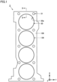
- Fig. 1 is an upper surface view showing a configuration of a gasket relating to Embodiment 1 of the present disclosure.
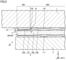
- Fig. 2 is a cross-sectional view in which the gasket of Fig. 1 is viewed in an II-II line arrow direction. Note that, in Fig. 2 , a cylinder head and a cylinder block are illustrated, for ease of understanding of the positional relationship of the gasket.
- a gasket 3 relating to Embodiment 1 of the present disclosure is a member that constitutes a vehicle engine. As shown in Fig. 2 , the gasket 3 is sandwiched between a cylinder head 1 and a cylinder block 2.
- the cylinder head 1 is fixed to the cylinder block 2 by sandwiching the gasket 3 therebetween.
- the cylinder head 1 is, for example, made of aluminum.
- a combustion chamber hole 20 is provided in the cylinder block 2.
- the combustion chamber hole 20 extends in a hole axis direction (Z-axis direction).
- Four combustion chamber holes, which are not illustrated, are disposed side by side in the X-axis direction in the cylinder block 2.
- the cylinder block 2 is, for example, made of aluminum or cast iron.
- the gasket 3 shares, with the cylinder block 2, a combustion chamber hole 30 that extends in the hole axis direction (Z-axis direction).
- the combustion chamber holes 30 are disposed side by side in the X-axis direction in the gasket 3.
- Through holes 31 are provided in the gasket 3.
- a plurality of the through holes 31 are provided with the intention of both fixing the cylinder head 1 and the cylinder block 2 by having bolts inserted through the through holes 31, and cooling the surroundings of the combustion chamber hole 30 by having a coolant flow through.
- the gasket 3 relating to Embodiment 1 of the present disclosure includes a first plate portion 100, a second plate portion 110, an intermediate plate portion 120, and a shim 130.
- the first plate portion 100 is a plate shaped member provided on the cylinder head 1 side.
- the first plate portion 100 is, for example, made of stainless steel.
- the first plate portion 100 has a convex portion 101 that protrudes to the cylinder block 2 side so as to surround the periphery of the combustion chamber hole 30.
- the convex portion 101 is provided at a position separated from a peripheral edge 30e of the combustion chamber hole 30.
- the first plate portion 100 abuts against the cylinder head 1. Specifically, the first plate portion 100 has a surface of a portion other than the convex portion 101 on the cylinder head 1 side that abuts against the cylinder head 1.
- the first plate portion 100 abuts against the intermediate plate portion 120 and the shim 130 on the cylinder block 2 side. Specifically, in the first plate portion 100, a surface of the convex portion 101 on the cylinder block 2 side abuts against the intermediate plate portion 120, and a surface of a portion near the peripheral edge 30e of the combustion chamber hole 30 on the cylinder block 2 side abuts against the shim 130.
- the first plate portion 100 has a substantially constant plate thickness.
- substantially constant related to a plate thickness of the present embodiment has a meaning that includes a variation in a plate thickness by a small machining tolerance compared to a change in a plate thickness of a gradually changing portion, which will be described below.
- the second plate portion 110 is a plate shaped member provided on the cylinder block 2 side.
- the second plate portion 110 is, for example, made of stainless steel.
- the second plate portion 110 has a convex portion 111 that protrudes to the cylinder head 1 side so as to surround the periphery of the combustion chamber hole 30.
- the convex portion 111 is provided at a position separated from the peripheral edge 30e of the combustion chamber hole 30.
- the second plate portion 110 abuts against the cylinder block 2.
- the second plate portion 110 has a surface of a portion other than the convex portion 111 on the cylinder block 2 side that abuts against the cylinder block 2.
- the second plate portion 110 abuts against the intermediate plate portion 120 on the cylinder head 1 side. Specifically, a surface of the convex portion 111 on the cylinder head 1 side abuts against the intermediate plate portion 120.
- the second plate portion 110 has a substantially constant plate thickness.
- the second plate portion 110 in the present embodiment has a plate thickness substantially the same as that of the first plate portion 100.
- the intermediate plate portion 120 is a plate shaped member sandwiched between the first plate portion 100 and the second plate portion 110.
- the intermediate plate portion 120 is, for example, made of stainless steel.
- the intermediate plate portion 120 is displaced to the cylinder block 2 side, at the portion that abuts against the shim 130. In this way, a gap between the first plate portion 100 and the intermediate plate portion 120 becomes larger with respect to a gap between the second plate portion 110 and the intermediate plate portion 120, in the Z-axis direction, at the portion of the combustion chamber hole 30 near the peripheral edge 30e.
- the intermediate plate portion 120 has a substantially constant plate thickness.
- the intermediate plate portion 120 in the present embodiment has a thicker plate thickness compared to each of the first plate portion 100 and the second plate portion 110.
- the shim 130 is a plate shaped member having an annular shape.
- the shim 130 is, for example, made of stainless steel.
- the shim 130 is disposed over the entire periphery of the peripheral edge 30e of the combustion chamber hole 30.
- the shim 130 is sandwiched between the first plate portion 100 and the intermediate plate portion 120. In this way, the first plate portion 100 can be interposed between the shim 130 and the cylinder head 1.
- a contact surface pressure can be suppressed from locally increasing, while increasing a contact surface pressure between the gasket 3 and the cylinder head 1.
- the effect of increasing a contact surface pressure between the gasket 3 and the cylinder head 1 becomes difficult to obtain.
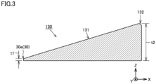
- Fig. 3 is a cross-sectional view showing a configuration of the shim included in the gasket relating to Embodiment 1 of the present disclosure.
- the shim 130 includes a gradually changing portion 131 with a thickness in the hole axis direction (Z-axis direction) that becomes thicker with a separation from the peripheral edge 30e of the combustion chamber hole 30.
- the gradually changing portion 131 has a thickness t1 at an end portion on the peripheral edge 30e side, and has a thickness t2 at an end portion on the opposite side to the peripheral edge 30e.
- the thickness of the gradually changing portion 131 becomes gradually thicker from the thickness t1 to the thickness t2 with a separation from the peripheral edge 30e.
- the gradually changing portion 131 is adjacent to the combustion chamber hole 30.
- the gradually changing portion 131 is provided over the entire periphery of the peripheral edge 30e of the combustion chamber hole 30. Since the shim 130 has an annular shape, the gradually changing portion 131 can be easily formed on the shim 130 by press machining or the like, compared to the case where the gradually changing portion is formed on the first plate portion, such as described below.
- the surface of the gradually changing portion 131 on the cylinder block 2 side has a flat shape. In this way, the shim 130 makes surface contact with the intermediate plate portion 120.
- the surface of the gradually changing portion 131 on the cylinder head 1 side is inclined linearly with respect to the surface of the gradually changing portion 131 on the cylinder block 2 side, when viewed in a peripheral direction of the combustion chamber hole 30.
- a gap is formed in the Z-axis direction between the first plate portion 100 and the shim 130 in a portion near the peripheral edge 30e.
- the shim 130 further includes a round edge portion 132.
- the round edge portion 132 is provided on an end of the shim 130 on an opposite side to the peripheral edge 30e side.
- the surface of each of the gradually changing portion 131 and the round edge portion 132 on the cylinder head 1 side is smoothly continuous.
- the shim 130 in the present embodiment has a trapezoid shape in which the plate thickness in the Z-axis direction gradually changes, when viewed in a peripheral direction of the combustion chamber hole 30, it is not limited to this configuration.
- the shim 130 may include the gradually changing portion 131 with a portion having a plate thickness that is substantially constant, when viewed in a peripheral direction of the combustion chamber hole 30.
- the gasket 3 in the present embodiment includes a first seal region SR1 and a second seal region SR2.
- the first seal region SR1 is a region in which the first plate portion 100, the second plate portion 110, the intermediate plate portion 120, and the shim 130 are stacked in the Z-axis direction.
- the first seal region SR1 is adjacent to the combustion chamber hole 30.
- the second seal region SR2 is a region in which the first plate portion 100, the second plate portion 110, and the intermediate plate portion 120 are stacked in the Z-axis direction.
- the second seal region SR2 is disposed on the outer periphery of the first seal region SR1 when viewed in the combustion chamber hole 30.
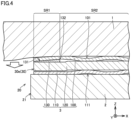
- Fig. 4 is a cross-sectional view showing a state where the cylinder head is thermally expanded in the gasket relating to Embodiment 1 of the present disclosure.
- the cylinder head 1 is at a high temperature by combustion of fuel gas within the combustion chamber hole 30, and thermally expands. In this way, the cylinder head 1 deforms so as to protrude to the combustion chamber hole 30 side at a portion adjacent to the combustion chamber hole 30. Namely, as shown in Fig. 4 , the cylinder head 1 deforms by thermally expanding in the arrow direction within Fig. 4 .
- the first plate portion 100 deforms along with the deformation by thermal expansion of the cylinder head 1. Specifically, a portion of the first plate portion 100 near the peripheral edge 30e deforms to the cylinder block 2 side. The gap between the first plate portion 100 and the shim 130 in a portion near the peripheral edge 30e disappears, in accordance with the deformation of the first plate portion 100. In this way, the gasket 3 is configured to enable deformation following the deformation by thermal expansion of the cylinder head 1.
- Fig. 5 is a cross-sectional view showing a configuration of the gasket relating to the comparative example.
- a combustion chamber hole 90 is provided in a gasket 9 relating to the comparative example.
- the gasket 9 includes a first plate portion 900, a second plate portion 910, an intermediate plate portion 920, and a shim 930.
- the shim 930 has a substantially constant plate thickness.
- Fig. 6 is a graph showing a change in a contact surface pressure between the gasket and the cylinder head with respect to a distance from the peripheral edge of the combustion chamber hole in Embodiment 1 and the comparative example of the present disclosure.
- a contact surface pressure (MPa) between the gasket and the cylinder head is shown on the vertical axis, and a distance (mm) from the peripheral edge of the combustion chamber hole is shown on the horizontal axis.
- Fig. 7 is a graph showing a relationship between a distance from the peripheral edge of the combustion chamber hole and a depth of an indentation formed in the cylinder head in Embodiment 1 and the comparative example of the present disclosure.
- a depth ( ⁇ m) of an indentation in the Z-axis direction formed in the cylinder head 1 is shown on the vertical axis
- a distance (mm) from the peripheral edge of the combustion chamber hole is shown on the horizontal axis.
- an indentation occurrence surface pressure which is a threshold of a contact surface pressure where an indentation is formed in the cylinder head 1, is P i .
- an indentation is formed on the entire region of the first seal region SR1 and on a portion of the second seal region SR2 adjacent to the first seal region SR1, by a contact surface pressure exceeding the indentation occurrence surface pressure P i .
- the indentation is deepest in a vicinity of the peripheral edge 90e of the combustion chamber hole 90, and becomes shallower with a separation from the vicinity of the peripheral edge 90e of the combustion chamber hole 90.
- the gasket 3 in the present embodiment since the shim 130 includes the gradually changing portion 131, and the gasket 3 is configured to enable deformation following the deformation by thermal expansion of the cylinder head 1, a contact surface pressure between the cylinder head 1 and a vicinity of the peripheral edge 30e of the combustion chamber hole 30 of the gasket 3 can be suppressed from locally increasing. As a result of this, a contact surface pressure between the cylinder head 1 and the gasket 3 becomes the indentation occurrence surface pressure P i or less, on the entire region of the first seal region SR1 and on the entire region of the second seal region SR2.
- the shim 130 can suppress an excessive increase in a contact surface pressure between the cylinder head 1 and the gasket 3, by including the gradually changing portion 131 that becomes thicker with a separation from the peripheral edge 30e of the combustion chamber hole 30. Consequently, since an indentation formed on the cylinder head 1 can be suppressed, the sealability of the gasket 3 can be maintained.
- the gasket 3 relating to Embodiment 1 of the present disclosure, since the shim 130 can have a simple structure, by having a surface of the gradually changing portion 131 on the cylinder head 1 side inclined linearly when viewed in a peripheral direction of the combustion chamber hole 30, the gasket 3 can be manufactured at low cost.
- gaskets relating to modified examples of Embodiment 1 of the present disclosure will be described. Since the gaskets relating to the following modified examples are different to the gasket 3 relating to Embodiment 1 of the present disclosure for the configuration of the shim, descriptions of configurations that are the same as those of the gasket 3 relating to Embodiment 1 of the present disclosure are not repeated.
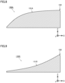
- Fig. 8 is a cross-sectional view showing a configuration of a shim included in a gasket relating to a first modified example of Embodiment 1 of the present disclosure.
- a surface of a gradually changing portion 131A on the cylinder head 1 side is inclined curvedly, when viewed in a peripheral direction of the combustion chamber hole 30.
- a surface of the gradually changing portion 131A on the cylinder head 1 side is inclined curvedly in a convex shape on the cylinder head 1 side.
- Fig. 9 is a cross-sectional view showing a configuration of a shim included in a gasket relating to a second modified example of Embodiment 1 of the present disclosure.
- a surface of a gradually changing portion 131B on the cylinder head 1 side is inclined while curving in a convex shape on the cylinder block 2 side.
- Fig. 10 is a cross-sectional view showing a configuration of a shim included in a gasket relating to a third modified example of Embodiment 1 of the present disclosure.
- a surface of a gradually changing portion 131C on the cylinder head 1 side is inclined so that a portion curved in a convex shape on the cylinder head 1 side and a portion curved in a convex shape on the cylinder block 2 side are connected to each other, and so as to increase with a separation from the peripheral edge of the combustion chamber hole.
- Fig. 11 is a cross-sectional view showing a configuration of a gasket relating to Embodiment 2 of the present disclosure.
- a gasket 3A relating to Embodiment 2 of the present disclosure includes a first plate portion 200, the second plate portion 110, the intermediate plate portion 120, and a shim 230.
- the first plate portion 200 includes a convex portion 201 that protrudes to the cylinder block 2 side so as to surround the periphery of the combustion chamber hole 30.
- the convex portion 201 is provided at a position separated from the peripheral edge 30e of the combustion chamber hole 30.
- the first plate portion 200 includes a gradually changing portion 202 with a thickness in a hole axis direction (Z-axis direction) that becomes thicker with a separation from the peripheral edge 30e of the combustion chamber hole 30.
- the first plate portion 200 abuts against the cylinder head 1. Specifically, the first plate portion 200 has a surface of a portion other than the convex portion 201 and the gradually changing portion 202 on the cylinder head 1 side that abuts against the cylinder head 1.
- the surface of the gradually changing portion 202 on the cylinder block 2 side has a flat shape. In this way, the gradually changing portion 202 makes surface contact with the shim 230.
- the surface of the gradually changing portion 202 on the cylinder head 1 side is inclined linearly with respect to the surface of the gradually changing portion 202 on the cylinder block 2 side, when viewed in a peripheral direction of the combustion chamber hole 30.
- a gap is formed in the Z-axis direction between the cylinder head 1 and the first plate portion 200 in a portion near the peripheral edge 30e.
- the surface of the gradually changing portion 202 on the cylinder head 1 side may be inclined curvedly with respect to the surface of the gradually changing portion 202 on the cylinder block 2 side, when viewed in a peripheral direction of the combustion chamber hole 30.
- the first plate portion 200 further includes a round edge portion 203.
- the round edge portion 203 is provided adjacent to an end of the gradually changing portion 202 on an opposite side to the peripheral edge 30e side in the first plate portion 200.
- the shim 230 is a plate shaped member having an annular shape. Specifically, the shim 230 is disposed over the entire periphery of the peripheral edge 30e of the combustion chamber hole 30, by having a substantially constant plate thickness.
- the gasket 3A relating to the present embodiment is configured to enable the influence of deformation by thermal expansion of the cylinder head 1 to be alleviated.
- a contact surface pressure between the cylinder head 1 and the gasket 3A becomes the indentation occurrence surface pressure P i or less, on the entire region of the first seal region SR1 and on the entire region of the second seal region SR2.
- an excessive increase in a contact surface pressure between the cylinder head 1 and the gasket 3A can be suppressed, by the first plate portion 200 including the gradually changing portion 202 that becomes thicker with a separation from the peripheral edge 30e of the combustion chamber hole 30. Consequently, since an indentation formed on the cylinder head 1 can be suppressed, the sealability of the gasket 3A can be maintained.
Landscapes
- Engineering & Computer Science (AREA)
- General Engineering & Computer Science (AREA)
- Mechanical Engineering (AREA)
- Chemical & Material Sciences (AREA)
- Combustion & Propulsion (AREA)
- Gasket Seals (AREA)
- Diaphragms For Electromechanical Transducers (AREA)
Applications Claiming Priority (2)
| Application Number | Priority Date | Filing Date | Title |
|---|---|---|---|
| JP2021084492A JP7582063B2 (ja) | 2021-05-19 | 2021-05-19 | ガスケット |
| PCT/JP2022/018568 WO2022244596A1 (fr) | 2021-05-19 | 2022-04-22 | Joint d'étanchéité |
Publications (3)
| Publication Number | Publication Date |
|---|---|
| EP4343178A1 true EP4343178A1 (fr) | 2024-03-27 |
| EP4343178A4 EP4343178A4 (fr) | 2024-10-30 |
| EP4343178B1 EP4343178B1 (fr) | 2026-04-29 |
Family
ID=84141351
Family Applications (1)
| Application Number | Title | Priority Date | Filing Date |
|---|---|---|---|
| EP22804510.0A Active EP4343178B1 (fr) | 2021-05-19 | 2022-04-22 | Joint d'étanchéité |
Country Status (10)
| Country | Link |
|---|---|
| US (1) | US12292113B2 (fr) |
| EP (1) | EP4343178B1 (fr) |
| JP (1) | JP7582063B2 (fr) |
| KR (1) | KR20240005030A (fr) |
| CN (1) | CN117321320A (fr) |
| AU (1) | AU2022278799B2 (fr) |
| BR (1) | BR112023022340A2 (fr) |
| CA (1) | CA3218763A1 (fr) |
| TW (1) | TWI825702B (fr) |
| WO (1) | WO2022244596A1 (fr) |
Family Cites Families (26)
| Publication number | Priority date | Publication date | Assignee | Title |
|---|---|---|---|---|
| JP3363208B2 (ja) | 1993-05-28 | 2003-01-08 | 大豊工業株式会社 | 金属ガスケット |
| US5618049A (en) * | 1993-06-04 | 1997-04-08 | Japan Metal Gasket Co., Ltd. | Metallic gasket |
| DE19520695C1 (de) * | 1995-06-07 | 1996-07-04 | Elringklinger Gmbh | Metallische Zylinderkopfdichtung |
| JP2841184B2 (ja) * | 1996-07-19 | 1998-12-24 | 石川ガスケット株式会社 | 金属ガスケット |
| US5895054A (en) * | 1996-07-19 | 1999-04-20 | Ishikawa Gasket Co., Ltd. | Metal gasket with a thick seal ring around a bore |
| DE19654283A1 (de) * | 1996-12-24 | 1998-06-25 | Reinz Dichtungs Gmbh | Metallische Flachdichtung |
| DE19719328C1 (de) * | 1997-05-08 | 1998-06-25 | Elringklinger Gmbh | Metallische Zylinderkopfdichtung |
| JPH11118038A (ja) * | 1997-10-15 | 1999-04-30 | Nippon Gasket Co Ltd | 金属製ガスケット |
| DE19950410A1 (de) * | 1999-10-20 | 2001-05-31 | Freudenberg Carl Fa | Federwegbegrenzer an Zylinderkopfdichtungen und Verfahren zu ihrer Herstellung |
| JP2001295930A (ja) | 2000-04-14 | 2001-10-26 | Taiho Kogyo Co Ltd | ガスケットのシムとその製造方法 |
| JP2001295937A (ja) * | 2000-04-14 | 2001-10-26 | Taiho Kogyo Co Ltd | シリンダヘッドガスケット |
| US6499743B2 (en) * | 2001-04-02 | 2002-12-31 | Federal-Mogul World Wide, Inc. | Gasket with dynamic joint motion control |
| DE10117178B4 (de) | 2001-04-05 | 2006-11-09 | Elringklinger Ag | Zylinderkopfdichtung |
| JP2005226806A (ja) * | 2004-02-16 | 2005-08-25 | Ishikawa Gasket Co Ltd | シリンダヘッドガスケット |
| DE102005039060A1 (de) * | 2005-08-18 | 2007-03-01 | Federal-Mogul Sealing Systems Gmbh | Zylinderkopfdichtung |
| JP2007139177A (ja) * | 2005-10-20 | 2007-06-07 | Japan Metal Gasket Co Ltd | ガスケット |
| JP4875356B2 (ja) * | 2005-10-24 | 2012-02-15 | 日本メタルガスケット株式会社 | ガスケット |
| WO2008084718A1 (fr) * | 2007-01-12 | 2008-07-17 | Nippon Gasket Co., Ltd. | Joint métallique |
| JP4386925B2 (ja) * | 2007-02-15 | 2009-12-16 | 石川ガスケット株式会社 | 金属積層形ガスケット |
| JP5136808B2 (ja) | 2010-06-23 | 2013-02-06 | 日本ガスケット株式会社 | シリンダヘッドガスケットとその製造方法 |
| JP5397347B2 (ja) | 2010-08-06 | 2014-01-22 | 日本ガスケット株式会社 | シリンダヘッドガスケットおよびその製造方法 |
| US9476382B2 (en) * | 2012-08-10 | 2016-10-25 | Dana Automotive Systems Group, Llc | Multi-layered gasket |
| USD746324S1 (en) * | 2013-01-04 | 2015-12-29 | Samsung Electronics Co., Ltd. | Display screen or portion thereof with animated graphical user interface |
| US10359003B2 (en) * | 2014-06-23 | 2019-07-23 | Tenneco Inc. | Cylinder head gasket with compression limiter and full bead loading |
| DE102014215596A1 (de) * | 2014-08-06 | 2016-02-11 | Elringklinger Ag | Zylinderkopfdichtung und Kombination aus einer Zylinderkopfdichtung und einem Verbrennungsmotor |
| JP7112647B2 (ja) | 2018-08-28 | 2022-08-04 | 日本ガスケット株式会社 | ガスケット |
-
2021
- 2021-05-19 JP JP2021084492A patent/JP7582063B2/ja active Active
-
2022
- 2022-04-22 WO PCT/JP2022/018568 patent/WO2022244596A1/fr not_active Ceased
- 2022-04-22 CN CN202280035682.2A patent/CN117321320A/zh active Pending
- 2022-04-22 KR KR1020237042106A patent/KR20240005030A/ko active Pending
- 2022-04-22 BR BR112023022340A patent/BR112023022340A2/pt unknown
- 2022-04-22 CA CA3218763A patent/CA3218763A1/fr active Pending
- 2022-04-22 US US18/561,521 patent/US12292113B2/en active Active
- 2022-04-22 AU AU2022278799A patent/AU2022278799B2/en active Active
- 2022-04-22 EP EP22804510.0A patent/EP4343178B1/fr active Active
- 2022-05-05 TW TW111116984A patent/TWI825702B/zh active
Also Published As
| Publication number | Publication date |
|---|---|
| JP2022178011A (ja) | 2022-12-02 |
| AU2022278799A1 (en) | 2023-12-07 |
| WO2022244596A1 (fr) | 2022-11-24 |
| BR112023022340A2 (pt) | 2023-12-26 |
| TW202246682A (zh) | 2022-12-01 |
| AU2022278799B2 (en) | 2025-07-31 |
| KR20240005030A (ko) | 2024-01-11 |
| JP7582063B2 (ja) | 2024-11-13 |
| EP4343178A4 (fr) | 2024-10-30 |
| TWI825702B (zh) | 2023-12-11 |
| CN117321320A (zh) | 2023-12-29 |
| US12292113B2 (en) | 2025-05-06 |
| US20240229736A1 (en) | 2024-07-11 |
| CA3218763A1 (fr) | 2022-11-24 |
| EP4343178B1 (fr) | 2026-04-29 |
Similar Documents
| Publication | Publication Date | Title |
|---|---|---|
| US8042815B2 (en) | Cylinder head gasket and engine | |
| KR20040084806A (ko) | 금속 개스킷 | |
| US9939066B2 (en) | Elastic sealing member radially inwardly of primary sealing bead | |
| US20080197579A1 (en) | Laminate-type gasket | |
| KR100950000B1 (ko) | 실린더 헤드 개스킷 | |
| EP1857717B1 (fr) | Joint de culasse d'un cylindre | |
| US8033263B2 (en) | Cylinder head gasket | |
| EP1116904A2 (fr) | Joint d'étanchéité métallique | |
| EP4343178A1 (fr) | Joint d'étanchéité | |
| EP1510735B1 (fr) | Joint d'étanchéité avec butée flexible | |
| EP3105475B1 (fr) | Joint de culasse doté d'éléments de contrôle de compression | |
| EP1510734B1 (fr) | Joint d'étanchéité avec butée flexible | |
| JP4137146B2 (ja) | ガスケット | |
| JP2010139007A (ja) | シリンダヘッドガスケット | |
| JP4541399B2 (ja) | 金属製ガスケット | |
| JP4541400B2 (ja) | 金属製ガスケット | |
| KR100647851B1 (ko) | 메탈 개스킷 | |
| US7108268B2 (en) | Metal laminate gasket | |
| US20060273526A1 (en) | Cylinder head gasket | |
| EP1561976B1 (fr) | Joint de culasse | |
| EP3564559B1 (fr) | Joint d'étanchéité métallique | |
| JP3211521U (ja) | エンジンのシール構造 | |
| JP4506082B2 (ja) | メタルガスケット | |
| CN102597582A (zh) | 扁形密封垫 | |
| JP2005291339A (ja) | 金属ガスケット |
Legal Events
| Date | Code | Title | Description |
|---|---|---|---|
| STAA | Information on the status of an ep patent application or granted ep patent |
Free format text: STATUS: THE INTERNATIONAL PUBLICATION HAS BEEN MADE |
|
| PUAI | Public reference made under article 153(3) epc to a published international application that has entered the european phase |
Free format text: ORIGINAL CODE: 0009012 |
|
| STAA | Information on the status of an ep patent application or granted ep patent |
Free format text: STATUS: REQUEST FOR EXAMINATION WAS MADE |
|
| 17P | Request for examination filed |
Effective date: 20231212 |
|
| AK | Designated contracting states |
Kind code of ref document: A1 Designated state(s): AL AT BE BG CH CY CZ DE DK EE ES FI FR GB GR HR HU IE IS IT LI LT LU LV MC MK MT NL NO PL PT RO RS SE SI SK SM TR |
|
| P01 | Opt-out of the competence of the unified patent court (upc) registered |
Free format text: CASE NUMBER: APP_38609/2024 Effective date: 20240627 |
|
| DAV | Request for validation of the european patent (deleted) | ||
| DAX | Request for extension of the european patent (deleted) | ||
| A4 | Supplementary search report drawn up and despatched |
Effective date: 20241002 |
|
| RIC1 | Information provided on ipc code assigned before grant |
Ipc: F02F 11/00 20060101ALI20240926BHEP Ipc: F16J 15/08 20060101AFI20240926BHEP |
|
| GRAP | Despatch of communication of intention to grant a patent |
Free format text: ORIGINAL CODE: EPIDOSNIGR1 |
|
| STAA | Information on the status of an ep patent application or granted ep patent |
Free format text: STATUS: GRANT OF PATENT IS INTENDED |
|
| INTG | Intention to grant announced |
Effective date: 20251219 |
|
| GRAS | Grant fee paid |
Free format text: ORIGINAL CODE: EPIDOSNIGR3 |
|
| GRAA | (expected) grant |
Free format text: ORIGINAL CODE: 0009210 |
|
| STAA | Information on the status of an ep patent application or granted ep patent |
Free format text: STATUS: THE PATENT HAS BEEN GRANTED |
|
| AK | Designated contracting states |
Kind code of ref document: B1 Designated state(s): AL AT BE BG CH CY CZ DE DK EE ES FI FR GB GR HR HU IE IS IT LI LT LU LV MC MK MT NL NO PL PT RO RS SE SI SK SM TR |
|
| REG | Reference to a national code |
Ref country code: CH Ref legal event code: F10 Free format text: ST27 STATUS EVENT CODE: U-0-0-F10-F00 (AS PROVIDED BY THE NATIONAL OFFICE) Effective date: 20260429 |