EP4343203A1 - Luminaire industriel - Google Patents
Luminaire industriel Download PDFInfo
- Publication number
- EP4343203A1 EP4343203A1 EP22197731.7A EP22197731A EP4343203A1 EP 4343203 A1 EP4343203 A1 EP 4343203A1 EP 22197731 A EP22197731 A EP 22197731A EP 4343203 A1 EP4343203 A1 EP 4343203A1
- Authority
- EP
- European Patent Office
- Prior art keywords
- industrial
- lamp
- segments
- signal
- designed
- Prior art date
- Legal status (The legal status is an assumption and is not a legal conclusion. Google has not performed a legal analysis and makes no representation as to the accuracy of the status listed.)
- Pending
Links
Images

Classifications
-
- F—MECHANICAL ENGINEERING; LIGHTING; HEATING; WEAPONS; BLASTING
- F21—LIGHTING
- F21V—FUNCTIONAL FEATURES OR DETAILS OF LIGHTING DEVICES OR SYSTEMS THEREOF; STRUCTURAL COMBINATIONS OF LIGHTING DEVICES WITH OTHER ARTICLES, NOT OTHERWISE PROVIDED FOR
- F21V33/00—Structural combinations of lighting devices with other articles, not otherwise provided for
- F21V33/0064—Health, life-saving or fire-fighting equipment
- F21V33/0076—Safety or security signalisation, e.g. smoke or burglar alarms, earthquake detectors; Self-defence devices
-
- F—MECHANICAL ENGINEERING; LIGHTING; HEATING; WEAPONS; BLASTING
- F21—LIGHTING
- F21V—FUNCTIONAL FEATURES OR DETAILS OF LIGHTING DEVICES OR SYSTEMS THEREOF; STRUCTURAL COMBINATIONS OF LIGHTING DEVICES WITH OTHER ARTICLES, NOT OTHERWISE PROVIDED FOR
- F21V23/00—Arrangement of electric circuit elements in or on lighting devices
- F21V23/003—Arrangement of electric circuit elements in or on lighting devices the elements being electronics drivers or controllers for operating the light source, e.g. for a LED array
-
- F—MECHANICAL ENGINEERING; LIGHTING; HEATING; WEAPONS; BLASTING
- F21—LIGHTING
- F21V—FUNCTIONAL FEATURES OR DETAILS OF LIGHTING DEVICES OR SYSTEMS THEREOF; STRUCTURAL COMBINATIONS OF LIGHTING DEVICES WITH OTHER ARTICLES, NOT OTHERWISE PROVIDED FOR
- F21V21/00—Supporting, suspending, or attaching arrangements for lighting devices; Hand grips
- F21V21/005—Supporting, suspending, or attaching arrangements for lighting devices; Hand grips for several lighting devices in an end-to-end arrangement, i.e. light tracks
-
- F—MECHANICAL ENGINEERING; LIGHTING; HEATING; WEAPONS; BLASTING
- F21—LIGHTING
- F21V—FUNCTIONAL FEATURES OR DETAILS OF LIGHTING DEVICES OR SYSTEMS THEREOF; STRUCTURAL COMBINATIONS OF LIGHTING DEVICES WITH OTHER ARTICLES, NOT OTHERWISE PROVIDED FOR
- F21V3/00—Globes; Bowls; Cover glasses
- F21V3/02—Globes; Bowls; Cover glasses characterised by the shape
-
- F—MECHANICAL ENGINEERING; LIGHTING; HEATING; WEAPONS; BLASTING
- F21—LIGHTING
- F21S—NON-PORTABLE LIGHTING DEVICES; SYSTEMS THEREOF; VEHICLE LIGHTING DEVICES SPECIALLY ADAPTED FOR VEHICLE EXTERIORS
- F21S2/00—Systems of lighting devices, not provided for in main groups F21S4/00 - F21S10/00 or F21S19/00, e.g. of modular construction
- F21S2/005—Systems of lighting devices, not provided for in main groups F21S4/00 - F21S10/00 or F21S19/00, e.g. of modular construction of modular construction
-
- F—MECHANICAL ENGINEERING; LIGHTING; HEATING; WEAPONS; BLASTING
- F21—LIGHTING
- F21V—FUNCTIONAL FEATURES OR DETAILS OF LIGHTING DEVICES OR SYSTEMS THEREOF; STRUCTURAL COMBINATIONS OF LIGHTING DEVICES WITH OTHER ARTICLES, NOT OTHERWISE PROVIDED FOR
- F21V23/00—Arrangement of electric circuit elements in or on lighting devices
- F21V23/04—Arrangement of electric circuit elements in or on lighting devices the elements being switches
- F21V23/0442—Arrangement of electric circuit elements in or on lighting devices the elements being switches activated by means of a sensor, e.g. motion or photodetectors
- F21V23/0471—Arrangement of electric circuit elements in or on lighting devices the elements being switches activated by means of a sensor, e.g. motion or photodetectors the sensor detecting the proximity, the presence or the movement of an object or a person
-
- F—MECHANICAL ENGINEERING; LIGHTING; HEATING; WEAPONS; BLASTING
- F21—LIGHTING
- F21V—FUNCTIONAL FEATURES OR DETAILS OF LIGHTING DEVICES OR SYSTEMS THEREOF; STRUCTURAL COMBINATIONS OF LIGHTING DEVICES WITH OTHER ARTICLES, NOT OTHERWISE PROVIDED FOR
- F21V23/00—Arrangement of electric circuit elements in or on lighting devices
- F21V23/04—Arrangement of electric circuit elements in or on lighting devices the elements being switches
- F21V23/0442—Arrangement of electric circuit elements in or on lighting devices the elements being switches activated by means of a sensor, e.g. motion or photodetectors
- F21V23/0485—Arrangement of electric circuit elements in or on lighting devices the elements being switches activated by means of a sensor, e.g. motion or photodetectors the sensor sensing the physical interaction between a user and certain areas located on the lighting device, e.g. a touch sensor
-
- F—MECHANICAL ENGINEERING; LIGHTING; HEATING; WEAPONS; BLASTING
- F21—LIGHTING
- F21V—FUNCTIONAL FEATURES OR DETAILS OF LIGHTING DEVICES OR SYSTEMS THEREOF; STRUCTURAL COMBINATIONS OF LIGHTING DEVICES WITH OTHER ARTICLES, NOT OTHERWISE PROVIDED FOR
- F21V23/00—Arrangement of electric circuit elements in or on lighting devices
- F21V23/06—Arrangement of electric circuit elements in or on lighting devices the elements being coupling devices, e.g. connectors
-
- F—MECHANICAL ENGINEERING; LIGHTING; HEATING; WEAPONS; BLASTING
- F21—LIGHTING
- F21W—INDEXING SCHEME ASSOCIATED WITH SUBCLASSES F21K, F21L, F21S and F21V, RELATING TO USES OR APPLICATIONS OF LIGHTING DEVICES OR SYSTEMS
- F21W2131/00—Use or application of lighting devices or systems not provided for in codes F21W2102/00-F21W2121/00
- F21W2131/40—Lighting for industrial, commercial, recreational or military use
- F21W2131/402—Lighting for industrial, commercial, recreational or military use for working places
-
- G—PHYSICS
- G08—SIGNALLING
- G08B—SIGNALLING SYSTEMS, e.g. PERSONAL CALLING SYSTEMS; ORDER TELEGRAPHS; ALARM SYSTEMS
- G08B5/00—Visible signalling systems, e.g. visible personal calling systems or remote indication of seats occupied
- G08B5/22—Visible signalling systems, e.g. visible personal calling systems or remote indication of seats occupied using electric transmission; using electromagnetic transmission
- G08B5/36—Visible signalling systems, e.g. visible personal calling systems or remote indication of seats occupied using electric transmission; using electromagnetic transmission using visible light sources
-
- G—PHYSICS
- G09—EDUCATION; CRYPTOGRAPHY; DISPLAY; ADVERTISING; SEALS
- G09F—DISPLAYING; ADVERTISING; SIGNS; LABELS OR NAME-PLATES; SEALS
- G09F13/00—Illuminated signs; Luminous advertising
- G09F13/04—Signs, boards or panels, illuminated from behind the insignia
- G09F13/0418—Constructional details
- G09F13/0436—Signs, boards or panels attached to ceilings
-
- G—PHYSICS
- G09—EDUCATION; CRYPTOGRAPHY; DISPLAY; ADVERTISING; SEALS
- G09F—DISPLAYING; ADVERTISING; SIGNS; LABELS OR NAME-PLATES; SEALS
- G09F9/00—Indicating arrangements for variable information in which the information is built-up on a support by selection or combination of individual elements
- G09F9/30—Indicating arrangements for variable information in which the information is built-up on a support by selection or combination of individual elements in which the desired character or characters are formed by combining individual elements
- G09F9/35—Indicating arrangements for variable information in which the information is built-up on a support by selection or combination of individual elements in which the desired character or characters are formed by combining individual elements being liquid crystals
-
- G—PHYSICS
- G09—EDUCATION; CRYPTOGRAPHY; DISPLAY; ADVERTISING; SEALS
- G09F—DISPLAYING; ADVERTISING; SIGNS; LABELS OR NAME-PLATES; SEALS
- G09F9/00—Indicating arrangements for variable information in which the information is built-up on a support by selection or combination of individual elements
- G09F9/30—Indicating arrangements for variable information in which the information is built-up on a support by selection or combination of individual elements in which the desired character or characters are formed by combining individual elements
- G09F9/37—Indicating arrangements for variable information in which the information is built-up on a support by selection or combination of individual elements in which the desired character or characters are formed by combining individual elements being movable elements
- G09F9/372—Indicating arrangements for variable information in which the information is built-up on a support by selection or combination of individual elements in which the desired character or characters are formed by combining individual elements being movable elements the positions of the elements being controlled by the application of an electric field
Definitions
- the invention relates to an industrial lamp with at least two segments.
- Lighting is often installed in machines and workplaces to illuminate an environment.
- information is often issued to workers at the same location via separate signaling devices.
- visual or acoustic signals are used to inform about faults or other events or to issue warning messages.
- the optically output signal may only be perceived with a delay. This is disadvantageous because it can take time for a worker to perceive the relevant information, which can lead to delays.
- the object of the invention is to eliminate the disadvantages known from the prior art in a simple and cost-effective manner.
- an industrial lamp with at least two segments, a first segment comprising a lamp which is designed to illuminate a room and/or an environment, and a second segment comprising a signal generator which is designed to to give a signal depending on information.
- Each of the segments can be controlled independently of the other segment.
- the Segments can simultaneously output a signal and illuminate a room and/or an environment.
- the basic idea of the invention is to provide several segments which basically enable the functions of lighting and signal output independently of one another. Nevertheless, both functions can be implemented at the same time in the same place with a single device. For example, if a signal is to be output, it is not absolutely necessary to (temporarily) forego the lighting function and vice versa.
- this can be intended to focus on the signal output, which can ensure that the signal is actually perceived.
- the lighting is at least dimmed or even switched off using the lamp.
- At least one of the segments can include both a light source and a signal generator.
- all segments of the industrial lamp include both a lamp and a signal generator. This allows the areas of the industrial luminaire that are used for lighting purposes and the areas of the industrial luminaire that are used for signaling purposes to be varied. In particular, this enables lighting and/or signal output in a specific environmental area or in a specific direction.
- indirect lighting of the environment or indirect signaling is ensured by lighting and/or signal output taking place along a wall towards the ceiling, provided the industrial light is mounted on a wall.
- the industrial lamp has at least one separating structure between the segments, which spatially separates the at least two segments from one another.
- the at least one separating structure is formed by an opaque web. This ensures that the light emitted by the lamps does not affect the signals given by the signaling devices. Disturbing scattered light can thus be avoided so that the segments of the industrial luminaire do not impair their respective functionalities.
- the industrial lamp has a base, with each of the at least two segments having a signaling surface that faces away from the base.
- the base allows for quick and easy assembly of the segments.
- the industrial light can also be mounted on a wall or ceiling using the base.
- the base can also serve to bring together electrical connections of the components present in the segments, in particular the lamps and the signal generators.
- Light for lighting purposes and/or signals can be output via the signaling surfaces. Spatial separation of the signaling surfaces from the base prevents the lighting and/or signaling function from being impaired or spatially restricted by cables and/or connections.
- there are no shadow effects caused by internal components of the industrial lamp since these are all assigned to the base, so that they are not arranged within the lighting direction of the lamp.
- the lighting means has a lighting direction that is (essentially) directed from the base towards at least one signaling surface.
- the signaling surfaces can each be designed as at least partially transparent surfaces. This enables light to be extracted from the respective segments.
- the light can, for example, be scattered as it exits using diffusers arranged on the partially transparent surfaces in order to improve the homogeneity of the lighting. This also ensures that no glare occurs.
- the signaling surface of at least one segment includes an at least partially translucent symbol, in particular a warning symbol.
- the light which is generated by a lamp and/or a signal generator, illuminates the transilluminable symbol as it emerges from the industrial lamp, so that people, for example workers, can clearly see the symbol when looking at the industrial lamp.
- the illuminated symbol can serve to warn people of at least one (predefined) danger, especially depending on the application, for example warning of gas leaks in the case of a gas processing plant.
- the symbol is not or barely visible to people when it is unlit. Whether a signal is output, can therefore be specified solely via the light emission.
- the symbols can, for example, be printed and/or glued and/or foiled and/or embossed directly from the inside or outside onto the at least partially transparent surface.
- the symbols can alternatively or additionally also be generated by active masking.
- an LCD or E-Ink display can be attached in or on one of the semi-transparent surfaces. Using the display, depending on an external signal, local masking or transparency adjustment can then take place, so that corresponding transilluminable symbols are formed in the display area.
- a further aspect of the invention provides that the segments are arranged in a semicircle or trapezoidal shape in a cross section of the industrial lamp.
- the cross section can be perpendicular to a longitudinal axis of the industrial lamp. This enables technically simple installation and allows lighting and/or signal output in all spatial or environmental directions when the industrial light is attached to a ceiling.
- the signal generator is designed to output a light signal, in particular a flashing signal.
- the industrial lamp includes a control that controls the signal generator with alternating and/or pulsed voltage and/or current curves. The signal generator then converts this into the flashing signal. It is conceivable that the control sets the changing and/or pulsed voltage and/or current curves based on external information. In principle, different flashing frequencies or flashing patterns can be generated. The flashing frequency and/or the flashing pattern can be unique to the particular danger that is to be warned about.
- a further aspect of the invention provides that the industrial lamp comprises three or more segments that adjoin one another and each have a signal generator and/or a light source.
- the signal transmitters and/or lamps of all segments can in particular be coordinated with one another in such a way that they emit light one after the other.
- a control can also be provided, which controls the signal generators and/or lamps one after the other (in time).
- the light emission of a rotating beacon can be imitated.
- a running light or a bar display can be created across multiple segments.
- the individual segments of the industrial lamp itself can be segmented again, in particular along a longitudinal axis of the industrial lamp.
- a segment can include several sub-segments through which movement patterns, such as running light functions, can be generated. This can draw people's attention to the industrial light and/or the corresponding segment.
- This type of sub-segmentation also makes it technically easy to implement a bar display, which can be used as a level indicator, for example.
- the sub-segments can light up in different colors, for example in the colors red, yellow and green. This means that a segment can be used as a traffic light, among other things.
- the sub-segments can in turn be separated from one another by separating structures in order to prevent scattering effects among the sub-segments.
- the industrial lamp includes a user interface which, when actuated, is designed to reset a signal emitted by the signal generator and/or to switch the at least one lamp on or off.
- a user interface which, when actuated, is designed to reset a signal emitted by the signal generator and/or to switch the at least one lamp on or off.
- the user interface is touch-sensitive and/or arranged on a signaling surface of a segment.
- the user interface can be designed as a touch sensor or touchscreen. This enables simple and intuitive operation.
- a further aspect of the invention provides that the industrial lamp comprises a first connection for transmitting information and/or energy to the industrial lamp, in particular a first IO-Link interface.
- a first connection for transmitting information and/or energy to the industrial lamp in particular a first IO-Link interface.
- This enables standardized communication of the industrial luminaire with other IO-Link devices, in particular sensors and actuators and/or other industrial luminaires and/or an IO-Link master.
- connections with 24 V, 48 V, 110 V and 250 V are particularly conceivable for the discrete energy supply of the industrial light.
- 24 V connections are often used in industry.
- the use of 48 V connections is also advantageous because twice the power can be transferred via the supply line compared to the 24 V connections that are prevalent in the prior art.
- the industrial light can in particular be equipped with a wide-voltage power supply that covers the nominal voltages of 24 V and 48 V.
- the industrial light has at least a second connection for transmitting information and/or energy, in particular a second IO-Link interface.
- the first and second connections are designed in such a way that several industrial lights can be connected together via them, in particular in a series connection.
- This design makes it technically easy to connect and install several industrial lights. Such an interconnection is suitable, for example, for lighting and/or signal output at assembly stations with several stations or aisles.
- the lighting strand formed in this way is an IO-Link device.
- the individual industrial lights can have a fixed assignment.
- the individual industrial lights can be controlled by a master via asynchronous mechanisms. Communication between the individual industrial lights preferably takes place via the IO-Link interfaces.
- first and second connections are designed such that in a series connection of industrial lights, information and/or data from a previous industrial light can be transmitted to the industrial light via the first connection and the information or data the previous luminaire and the industrial luminaire can be transferred to a subsequent industrial luminaire.
- the industrial lamp can be connected to various other components.
- These can be, for example, sensors or actuators, in particular buttons or limit switches, with which signaling can be triggered and/or the lighting can be switched on and/or off and/or an error can be reset.
- Such a further component is a motion detector that can be connected to the industrial light and with which the lighting of the industrial light is controlled can be switched on when a person moves in the sensor field of the motion detector.
- the industrial light itself can also include a permanently installed motion detector.
- the other components can be connected to the industrial light directly via its outputs, in particular plugs. Alternatively, a connection can also be made via digital communication and/or radio.
- FIG. 1 shows a schematic sectional view of an industrial lamp 10 according to the invention.
- the industrial lamp 10 is elongated and includes a base 12 and three segments 14, which are spatially separated from one another by separating structures 16.
- the separating structures 16 are opaque webs 18 extending from the base 12, for example made of an injection-molded plastic or a sheet of metal.
- the webs 18 protrude vertically from a base area of the base 12.
- the three segments 14 are arranged next to each other in a trapezoidal shape in a cross section perpendicular to a longitudinal axis 20 of the industrial lamp 10, in particular in such a way that the three segments 14 together with the base 12 form an isosceles and symmetrical trapezoid in the cross section mentioned form. This results in maximum differentiation between the three segments 14.
- the middle of the three segments 14 has a light source 22, for example a light-emitting diode or a light-emitting diode arrangement.
- the lamp 22 is designed to illuminate a room and/or an environment, in particular a workplace.
- the signal generator 24 is also a light-emitting diode or a light-emitting diode arrangement that is controlled by a controller.
- the control Depending on the information, for example an entered warning message, the control generates electrical signals, which are then converted into light signals by the signal generator 24.
- the light signals can be color signals and/or flashing light signals. This draws the attention of signal receivers, in particular people such as workers, to the industrial light 10 and/or to the signals emitted.
- signal generators 24 are also conceivable, for example acoustic signal generators.
- the three segments 14 can be controlled independently of one another in the exemplary embodiment.
- a light can be generated for lighting purposes using the middle segment 14 and at the same time a signal can be output using the outer segments 14.
- a lighting function and a signaling function of the industrial light 10 can be used at the same time.
- one or more of the segments 14 includes both a light source 22 and a signal generator 24.
- one or more of the segments 14 are equipped with light-emitting diodes, which can be used both as lamps 22 and as signal generators 24.
- the lamp 22 arranged in the middle segment 14 can also be used as a signal generator 24 at the same time.
- the control can control the signal generators 24 or lamps 22 of the three segments 14 in such a way that they emit light signals one after the other. For example, the light emission of a semicircular rotating beacon can be imitated.
- the three segments 14 in the exemplary embodiment each have a partially transparent light-scattering signaling surface 26.
- the lighting means 22 or signal generators 24 are arranged between the base 12 and the respective signaling surface 26. This allows for easy assembly and/or maintenance. For example, if a lamp 22 or signal generator 24 of a segment 14 is defective, the associated signaling surface 26 can simply be removed and the defective part replaced.
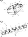
- Figure 2 shows a schematic three-dimensional representation of the industrial lamp 10 viewed from one side.
- the signaling surface 26 of one of the side segments 14 has a plurality of symbols 28, in particular warning symbols 30.
- the symbols 28 can, for example, be printed directly on the signaling surface 26 or be on a film that has been applied to the signaling surface 26 or back-injected during production.
- the symbols 28 can be transilluminated. This means that the symbols 28 are easily recognizable to people when the signal generator 24 of the corresponding segment 14 emits a light signal.
- the industrial lamp 10 has a user interface 32.
- the user interface 32 is a touch-sensitive touchscreen 34, which is formed on the signaling surface 26 of one of the outer segments 14.
- the user interface 32 makes it possible to reset an output signal and/or to switch the lamp 22 on or off. For example, if a user wants to reset a warning signal emitted by the industrial light 10, he can do this by tapping the corresponding symbol 28.
- Industrial lamp 10 shown also has a motion detector 36. This is designed to detect movements of nearby people and to switch the lamp 22 on and/or off in the event of a detected movement. Alternatively or additionally, the motion detector 36 can also be designed to control one of the signal generators 24 in the event of a detected movement so that it outputs or resets a signal.
- connection 38 on one end face.
- this is a discrete interface, in particular an IO-Link interface 40, via which the industrial light 10 can be controlled and supplied with electrical energy.
- the nominal voltage of connection 38 is 24 V and/or 48 V.
- the industrial lamp 10 also has a second connection 42 on an end face opposite the first connection 38. This one is in Figure 2 covered by the industrial light 10.
- the second connection 42 is also designed as an IO-Link interface 40 and is intended for transmitting information and/or energy to the industrial lamp 10 or from the industrial lamp 10 to other elements.
- the first and second connections 38, 42 are designed so that several industrial lights 10 can be connected together via them.
- Figure 3 shows such an interconnection in the form of a series connection 44 of three industrial lights 10.
- the first connections 38 of the industrial lights 10 are designed to transmit the data of all industrial lights 10 preceding the series in the series connection 44.
- the second connections 42 are also designed to pass on the data of all industrial lights 10 preceding the row to the industrial lamp 10 following the row.
- the industrial lights 10 can alternatively or additionally also have one or more other types of connection, in particular discrete multi-core IO-Link cables as well as WiFi, radio and/or Bluetooth.
- the industrial light 10 is connected to an additional sensor 46, for example a door opening sensor, via the second connection 42.
- the industrial lamp 10 can also be connected to other input devices 48, via which users can, for example, enter information, switch the lamp 22 on or off and/or reset output signals.
Landscapes
- Engineering & Computer Science (AREA)
- General Engineering & Computer Science (AREA)
- Microelectronics & Electronic Packaging (AREA)
- Computer Security & Cryptography (AREA)
- Environmental & Geological Engineering (AREA)
- Arrangement Of Elements, Cooling, Sealing, Or The Like Of Lighting Devices (AREA)
- Circuit Arrangement For Electric Light Sources In General (AREA)
Priority Applications (4)
| Application Number | Priority Date | Filing Date | Title |
|---|---|---|---|
| EP22197731.7A EP4343203A1 (fr) | 2022-09-26 | 2022-09-26 | Luminaire industriel |
| DE102023125389.1A DE102023125389A1 (de) | 2022-09-26 | 2023-09-19 | Industrieleuchte |
| CN202311229927.8A CN117759915A (zh) | 2022-09-26 | 2023-09-22 | 工业发光装置 |
| US18/372,223 US12313248B2 (en) | 2022-09-26 | 2023-09-25 | Industrial luminaire |
Applications Claiming Priority (1)
| Application Number | Priority Date | Filing Date | Title |
|---|---|---|---|
| EP22197731.7A EP4343203A1 (fr) | 2022-09-26 | 2022-09-26 | Luminaire industriel |
Publications (1)
| Publication Number | Publication Date |
|---|---|
| EP4343203A1 true EP4343203A1 (fr) | 2024-03-27 |
Family
ID=83457058
Family Applications (1)
| Application Number | Title | Priority Date | Filing Date |
|---|---|---|---|
| EP22197731.7A Pending EP4343203A1 (fr) | 2022-09-26 | 2022-09-26 | Luminaire industriel |
Country Status (4)
| Country | Link |
|---|---|
| US (1) | US12313248B2 (fr) |
| EP (1) | EP4343203A1 (fr) |
| CN (1) | CN117759915A (fr) |
| DE (1) | DE102023125389A1 (fr) |
Families Citing this family (1)
| Publication number | Priority date | Publication date | Assignee | Title |
|---|---|---|---|---|
| EP4697863A1 (fr) * | 2024-08-12 | 2026-02-18 | Murrelektronik GmbH | Système d'éclairage de plafond et procédé de fonctionnement d'un système d'éclairage de plafond |
Citations (6)
| Publication number | Priority date | Publication date | Assignee | Title |
|---|---|---|---|---|
| EP3029645A1 (fr) * | 2014-12-04 | 2016-06-08 | FESTO AG & Co. KG | Dispositif d'affichage et actionneur doté d'un dispositif d'affichage |
| US20170316660A1 (en) * | 2016-04-29 | 2017-11-02 | Hubbell Incorporated | Light fixture |
| US20190376656A1 (en) * | 2015-06-05 | 2019-12-12 | Schreder S.A. | Luminaires |
| KR20190141989A (ko) * | 2018-06-15 | 2019-12-26 | (주)맵시전자 | 작업등 |
| DE102019105997A1 (de) * | 2019-03-08 | 2020-09-10 | Weiss Alarm- und Sicherheitstechnik GmbH | Steckdosenlichtvorrichtung zum Detektieren und Signalisieren von Kohlenmonoxid |
| WO2021222951A1 (fr) * | 2020-05-05 | 2021-11-11 | Opus Novo Gmbh | Module d'éclairage |
Family Cites Families (7)
| Publication number | Priority date | Publication date | Assignee | Title |
|---|---|---|---|---|
| US9930756B2 (en) | 2008-03-27 | 2018-03-27 | Cree, Inc. | Apparatus, methods and systems for providing lighting and communication |
| DE102012023190B4 (de) | 2012-11-28 | 2018-10-31 | Balluff Gmbh | Signalsäule |
| US9699856B2 (en) | 2015-03-25 | 2017-07-04 | Cree, Inc. | Upgradeable lighting fixture |
| DE102015122811A1 (de) | 2015-12-23 | 2017-06-29 | Balluff Gmbh | Anzeigevorrichtung und Verfahren zum Ansteuern einer Anzeigevorrichtung |
| US11136000B2 (en) * | 2017-11-17 | 2021-10-05 | Magna Closures Inc. | Touch and gesture pad for swipe/tap entry verification system |
| DE102019109182A1 (de) | 2018-04-18 | 2019-10-24 | Balluff Gmbh | Segmentierte Leuchtanzeige |
| US10482728B2 (en) | 2018-04-18 | 2019-11-19 | Balluff Gmbh | Segmented light indicator |
-
2022
- 2022-09-26 EP EP22197731.7A patent/EP4343203A1/fr active Pending
-
2023
- 2023-09-19 DE DE102023125389.1A patent/DE102023125389A1/de active Pending
- 2023-09-22 CN CN202311229927.8A patent/CN117759915A/zh active Pending
- 2023-09-25 US US18/372,223 patent/US12313248B2/en active Active
Patent Citations (6)
| Publication number | Priority date | Publication date | Assignee | Title |
|---|---|---|---|---|
| EP3029645A1 (fr) * | 2014-12-04 | 2016-06-08 | FESTO AG & Co. KG | Dispositif d'affichage et actionneur doté d'un dispositif d'affichage |
| US20190376656A1 (en) * | 2015-06-05 | 2019-12-12 | Schreder S.A. | Luminaires |
| US20170316660A1 (en) * | 2016-04-29 | 2017-11-02 | Hubbell Incorporated | Light fixture |
| KR20190141989A (ko) * | 2018-06-15 | 2019-12-26 | (주)맵시전자 | 작업등 |
| DE102019105997A1 (de) * | 2019-03-08 | 2020-09-10 | Weiss Alarm- und Sicherheitstechnik GmbH | Steckdosenlichtvorrichtung zum Detektieren und Signalisieren von Kohlenmonoxid |
| WO2021222951A1 (fr) * | 2020-05-05 | 2021-11-11 | Opus Novo Gmbh | Module d'éclairage |
Also Published As
| Publication number | Publication date |
|---|---|
| DE102023125389A1 (de) | 2024-03-28 |
| CN117759915A (zh) | 2024-03-26 |
| US12313248B2 (en) | 2025-05-27 |
| US20240102641A1 (en) | 2024-03-28 |
Similar Documents
| Publication | Publication Date | Title |
|---|---|---|
| EP2067382B1 (fr) | Module d'exploitation et procédé d'utilisation de moyens d'éclairage | |
| DE69309226T3 (de) | Lichtvorhang mit Anzeigern für einzelne Lichtstrahlen und Betriebsverfahren | |
| EP2209099B1 (fr) | Dispositif de lampe de signalisation doté d'au moins deux lampes de signalisation | |
| DE102017106811B4 (de) | Vorrichtung und zugehöriges Verfahren zur selbständigen Adresskonfiguration konfektionierbarer, flexibler LED-Bänder | |
| DE102017106812B4 (de) | Vorrichtung und zugehöriges Verfahren zur selbständigen Adresskonfiguration konfektionierbarer, flexibler LED-Sensor-Bänder | |
| EP2182776B1 (fr) | Lampe de signalisation dotée d'une unité de socle et d'au moins une unité d'éclairage | |
| EP2056268B1 (fr) | Lampe de signalisation destinée à la signalisation visuelle d'au moins un état de fonctionnement | |
| DE102017106813B4 (de) | Vorrichtung und zugehöriges Verfahren zur selbständigen Adresskonfiguration konfektionierbarer, flexibler Sensor-Bänder | |
| DE102011000816A1 (de) | Selbsttätig verfahrbares Gerät | |
| DE10149860A1 (de) | Sicherheitsleuchten für Fluchtwege und ein Lichtleitsystem zur Steuerung dieser Sicherheitsleuchten | |
| DE102023125389A1 (de) | Industrieleuchte | |
| DE102012202474B4 (de) | System zur Akzentbeleuchtung oder zur Erzeugung von Leuchteffekten sowie Leuchtelement | |
| EP3549824B1 (fr) | Dispositif d'éclairage permettant d'éclairer un habitacle d'un véhicule | |
| DE102008041696B4 (de) | Farbsignalisierungslinse | |
| LU503513B1 (de) | Bedieneinheit und Verfahren zum Bedienen einer Anlage mit einer Bedieneinheit | |
| DE102016122933B4 (de) | Steuer- und Überwachungsschaltung zum Steuern einer Beleuchtungsanwendung in einem Fahrzeug | |
| EP3764746B1 (fr) | Appareil de commande | |
| DE102018201852B4 (de) | Bildschirmvorrichtung mit steuerbarem Zusatz-Leuchtelement | |
| EP3368822B1 (fr) | Dispositif de representation d'image | |
| EP2131627B1 (fr) | Eclairage | |
| DE102016109464A1 (de) | Optische Bestückungsanzeige für Kabelbäume | |
| EP3934384B1 (fr) | Agencement destiné à la commande de del | |
| EP2093725A1 (fr) | Surveillance à l'aide d'un élément de capteur | |
| WO2007104417A2 (fr) | Transmission de données dans un système composé d'unités techniques textiles | |
| DE102024132381A1 (de) | Labor-, Elektronik- und/oder Prüfarbeitstisch oder elektronisches Mess- und/oder Prüfgerät |
Legal Events
| Date | Code | Title | Description |
|---|---|---|---|
| PUAI | Public reference made under article 153(3) epc to a published international application that has entered the european phase |
Free format text: ORIGINAL CODE: 0009012 |
|
| STAA | Information on the status of an ep patent application or granted ep patent |
Free format text: STATUS: THE APPLICATION HAS BEEN PUBLISHED |
|
| AK | Designated contracting states |
Kind code of ref document: A1 Designated state(s): AL AT BE BG CH CY CZ DE DK EE ES FI FR GB GR HR HU IE IS IT LI LT LU LV MC MK MT NL NO PL PT RO RS SE SI SK SM TR |
|
| STAA | Information on the status of an ep patent application or granted ep patent |
Free format text: STATUS: REQUEST FOR EXAMINATION WAS MADE |
|
| 17P | Request for examination filed |
Effective date: 20240605 |
|
| RBV | Designated contracting states (corrected) |
Designated state(s): AL AT BE BG CH CY CZ DE DK EE ES FI FR GB GR HR HU IE IS IT LI LT LU LV MC MK MT NL NO PL PT RO RS SE SI SK SM TR |
|
| STAA | Information on the status of an ep patent application or granted ep patent |
Free format text: STATUS: EXAMINATION IS IN PROGRESS |