EP4343206B1 - Injecteur de carburant de moteur à turbine à gaz avec plusieurs circuits de carburant - Google Patents
Injecteur de carburant de moteur à turbine à gaz avec plusieurs circuits de carburant Download PDFInfo
- Publication number
- EP4343206B1 EP4343206B1 EP23199527.5A EP23199527A EP4343206B1 EP 4343206 B1 EP4343206 B1 EP 4343206B1 EP 23199527 A EP23199527 A EP 23199527A EP 4343206 B1 EP4343206 B1 EP 4343206B1
- Authority
- EP
- European Patent Office
- Prior art keywords
- fuel
- trajectory
- percentage
- circuit
- nozzle
- Prior art date
- Legal status (The legal status is an assumption and is not a legal conclusion. Google has not performed a legal analysis and makes no representation as to the accuracy of the status listed.)
- Active
Links
Images


Classifications
-
- F—MECHANICAL ENGINEERING; LIGHTING; HEATING; WEAPONS; BLASTING
- F23—COMBUSTION APPARATUS; COMBUSTION PROCESSES
- F23D—BURNERS
- F23D14/00—Burners for combustion of a gas, e.g. of a gas stored under pressure as a liquid
- F23D14/46—Details
- F23D14/48—Nozzles
- F23D14/58—Nozzles characterised by the shape or arrangement of the outlet or outlets from the nozzle, e.g. of annular configuration
-
- F—MECHANICAL ENGINEERING; LIGHTING; HEATING; WEAPONS; BLASTING
- F23—COMBUSTION APPARATUS; COMBUSTION PROCESSES
- F23R—GENERATING COMBUSTION PRODUCTS OF HIGH PRESSURE OR HIGH VELOCITY, e.g. GAS-TURBINE COMBUSTION CHAMBERS
- F23R3/00—Continuous combustion chambers using liquid or gaseous fuel
- F23R3/28—Continuous combustion chambers using liquid or gaseous fuel characterised by the fuel supply
- F23R3/283—Attaching or cooling of fuel injecting means including supports for fuel injectors, stems, or lances
-
- F—MECHANICAL ENGINEERING; LIGHTING; HEATING; WEAPONS; BLASTING
- F02—COMBUSTION ENGINES; HOT-GAS OR COMBUSTION-PRODUCT ENGINE PLANTS
- F02C—GAS-TURBINE PLANTS; AIR INTAKES FOR JET-PROPULSION PLANTS; CONTROLLING FUEL SUPPLY IN AIR-BREATHING JET-PROPULSION PLANTS
- F02C9/00—Controlling gas-turbine plants; Controlling fuel supply in air- breathing jet-propulsion plants
- F02C9/26—Control of fuel supply
- F02C9/263—Control of fuel supply by means of fuel metering valves
-
- F—MECHANICAL ENGINEERING; LIGHTING; HEATING; WEAPONS; BLASTING
- F23—COMBUSTION APPARATUS; COMBUSTION PROCESSES
- F23D—BURNERS
- F23D11/00—Burners using a direct spraying action of liquid droplets or vaporised liquid into the combustion space
- F23D11/10—Burners using a direct spraying action of liquid droplets or vaporised liquid into the combustion space the spraying being induced by a gaseous medium, e.g. water vapour
- F23D11/12—Burners using a direct spraying action of liquid droplets or vaporised liquid into the combustion space the spraying being induced by a gaseous medium, e.g. water vapour characterised by the shape or arrangement of the outlets from the nozzle
-
- F—MECHANICAL ENGINEERING; LIGHTING; HEATING; WEAPONS; BLASTING
- F23—COMBUSTION APPARATUS; COMBUSTION PROCESSES
- F23R—GENERATING COMBUSTION PRODUCTS OF HIGH PRESSURE OR HIGH VELOCITY, e.g. GAS-TURBINE COMBUSTION CHAMBERS
- F23R3/00—Continuous combustion chambers using liquid or gaseous fuel
- F23R3/28—Continuous combustion chambers using liquid or gaseous fuel characterised by the fuel supply
-
- F—MECHANICAL ENGINEERING; LIGHTING; HEATING; WEAPONS; BLASTING
- F23—COMBUSTION APPARATUS; COMBUSTION PROCESSES
- F23D—BURNERS
- F23D11/00—Burners using a direct spraying action of liquid droplets or vaporised liquid into the combustion space
- F23D11/36—Details
- F23D11/38—Nozzles; Cleaning devices therefor
Definitions
- This disclosure relates generally to a gas turbine engine and, more particularly, to a fuel injector for the gas turbine engine.
- a gas turbine engine may include multiple fuel injectors for delivering fuel to a combustor for combustion with compressed air.
- fuel injectors for delivering fuel to a combustor for combustion with compressed air.
- Various types and configurations of fuel injectors are known in the art. While these known fuel injectors have various benefits, there is still room in the art for improvement. There is a need in the art, in particular, for a fuel injector which can be tuned for multiple different modes of gas turbine engine operation.
- DE102007034737A1 discloses a prior art assembly according to the preamble of claim 1.
- an assembly is provided for a gas turbine engine according to claim 1.
- the assembly may also include a fuel system including a fuel source and the fuel injector.
- the fuel system may be configured to deliver fuel from the fuel source through the fuel injector where the first fuel circuit provides a first percentage of the fuel, the second fuel circuit provides a second percentage of the fuel and the third fuel circuit provides a third percentage of the fuel.
- the first percentage and the second percentage may be greater than the third percentage.
- the third percentage may be greater than the first percentage and the second percentage.
- the second percentage may be within ten percent of the third percentage.
- the second percentage may be greater than the first percentage.
- the first fuel circuit may be configured to direct fuel out of the nozzle through the first fuel outlet along a first trajectory.
- the second fuel circuit may be configured to direct fuel out of the nozzle through a first of the second fuel outlets along a second trajectory that is angularly offset from the first trajectory.
- the third fuel circuit may be configured to direct fuel out of the nozzle through a first of the third fuel outlets along a third trajectory that is angularly offset from the first trajectory.
- the second trajectory may be angularly offset from the first trajectory by a first angle.
- the third trajectory may be angularly offset from the first trajectory by a second angle that may be different than the first angle.
- the second trajectory may be angularly offset from the first trajectory by a first angle.
- the third trajectory may be angularly offset from the first trajectory by a second angle that may be equal to the first angle.
- the first trajectory may be coaxial with the axis.
- the first fuel outlet may be coaxial with the axis.
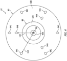
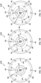
- a first of the third fuel outlets may be circumferentially aligned with a first of the second fuel outlets.
- a first of the third fuel outlets may be circumferentially offset from each of the second fuel outlets.
- the second fuel outlet array may be disposed radially outboard of the first fuel outlet by a first radial distance.
- the third fuel outlet array may be disposed radially outboard of the first fuel outlet by a second radial distance that is greater than the first radial distance.
- the second fuel outlet array may be radially aligned with the third fuel outlet array.
- the second fuel circuit may also include a passage that extends to a first of the second nozzle outlets.
- the passage may converge as the passage that extends towards the first of the second nozzle outlets.
- the second fuel circuit may also include a passage that extends to a first of the second nozzle outlets.
- the passage may have a uniform lateral size.
- a first of the second nozzle outlets may have a circular cross-sectional geometry.
- a first of the second nozzle outlets may have an elongated cross-sectional geometry.
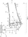
- the fuel injector may also include a stem.
- the nozzle may project axially out from the stem along the axis to the nozzle tip.
- the first fuel circuit may also include a first fuel conduit within the stem and fluidly coupled to the first fuel outlet.
- the second fuel circuit may also include a second fuel conduit within the stem and fluidly coupled to the second fuel outlets.
- the third fuel circuit may also include a third fuel conduit within the stem and fluidly coupled to the third fuel outlets.
- the present disclosure may include any one or more of the individual features disclosed above and/or below alone or in any combination thereof.
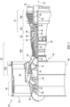
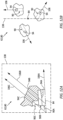
- FIG. 1 is a side cutaway illustration of a gas turbine engine 20.
- This gas turbine engine 20 extends along an axial centerline 22 between an upstream airflow inlet 24 and a downstream airflow exhaust 26.
- the gas turbine engine 20 includes a fan section 28, a compressor section 29, a combustor section 30 and a turbine section 31.
- the compressor section 29 includes a low pressure compressor (LPC) section 29A and a high pressure compressor (HPC) section 29B.
- the turbine section 31 includes a high pressure turbine (HPT) section 31A and a low pressure turbine (LPT) section 31B.
- the engine sections 28, 29A, 29B, 30, 31A and 31B are arranged sequentially along the axial centerline 22 within an engine housing 34.
- This engine housing 34 includes an inner case 36 (e.g., a core case) and an outer case 38 (e.g., a fan case).
- the inner case 36 may house one or more of the engine sections 29A, 29B, 30, 31A and 31B; e.g., a core of the gas turbine engine 20.
- the outer case 38 may house at least the fan section 28.
- the fan section 28, the LPC section 29A, the HPC section 29B, the HPT section 31A and the LPT section 31B each include a respective bladed rotor 40-44.
- Each of these bladed rotors 40-44 includes a plurality of rotor blades arranged circumferentially around and connected to one or more respective rotor disks.
- the rotor blades may be formed integral with or mechanically fastened, welded, brazed, adhered and/or otherwise attached to the respective rotor disk(s).
- the fan rotor 40 is connected to a geartrain 46, for example, through a fan shaft 48.
- the geartrain 46 and the LPC rotor 41 are connected to and driven by the LPT rotor 44 through a low speed shaft 49.
- the HPC rotor 42 is connected to and driven by the HPT rotor 43 through a high speed shaft 50.
- the shafts 48-50 are rotatably supported by a plurality of bearings 52; e.g., rolling element and/or thrust bearings. Each of these bearings 52 is connected to the engine housing 34 by at least one stationary structure such as, for example, an annular support strut.
- This air is directed through the fan section 28 and into a core flowpath 54 and a bypass flowpath 56.
- the core flowpath 54 extends sequentially through the engine sections 29A-31B; e.g., the engine core.
- the air within the core flowpath 54 may be referred to as "core air”.
- the bypass flowpath 56 extends through a bypass duct, which bypasses and may be radially outboard of the engine core.
- the air within the bypass flowpath 56 may be referred to as "bypass air".
- the core air is compressed by the LPC rotor 41 and the HPC rotor 42 and directed into a (e.g., annular) combustion chamber 58 of a (e.g., annular) combustor 60 in the combustor section 30.
- Fuel is injected into the combustion chamber 58 by one or more fuel injectors 62 (one schematically shown in FIG. 1 ) and mixed with the compressed core air to provide a fuel-air mixture.
- This fuel-air mixture is ignited and combustion products thereof flow through and sequentially cause the HPT rotor 43 and the LPT rotor 44 to rotate.
- the rotation of the HPT rotor 43 and the LPT rotor 44 respectively drive rotation of the HPC rotor 42 and the LPC rotor 41 and, thus, compression of the air received from a core airflow inlet.
- the rotation of the LPT rotor 44 also drives rotation of the fan rotor 40, which fan rotor 40 propels bypass air through and out of the bypass flowpath 56.
- the propulsion of the bypass air may account for a majority of thrust generated by the gas turbine engine 20, e.g., more than seventy-five percent (75%) of engine thrust.
- the gas turbine engine 20 of the present disclosure is not limited to the foregoing exemplary thrust ratio.
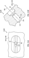
- each of the fuel circuits 90 may be provided with common outlet orifice configurations; e.g., the configuration of FIG. 9, 10A or 11A . In other embodiments, any two of the fuel circuits 90 may be provided with common outlet orifice configurations while the other fuel circuit is provided with another outlet orifice configuration. In still other embodiments, each fuel circuit 90 may be provided with a discrete outlet orifice configuration.
- each of the fuel circuits 90 may be configured for common trajectory orientations; e.g., the orientation of FIG. 12A or 12B .
- the fuel circuits 90 (e.g., 90B and 90C) may be configured for discrete trajectory orientations.
- the second fuel circuit 90B may be configured for the trajectory orientation of FIG. 12B and the third fuel circuit 90C may be configured for the trajectory orientation of FIG. 12A .
- both the second fuel circuit 90B and the third fuel circuit 90C may be configured for the trajectory orientations of FIG. 12B ; however, a degree of trajectory skew from the reference plane may be different and/or in an opposing direction.
- the fuel system 66 and its fuel injector(s) 62 may be included in various gas turbine engines other than the one described above.
- the fuel system 66 and its fuel injector(s) 62 may be included in a geared gas turbine engine where a geartrain connects one or more shafts to one or more rotors in a fan section, a compressor section and/or any other engine section.
- the fuel system 66 and its fuel injector(s) 62 may be included in a gas turbine engine configured without a geartrain; e.g., a direct drive gas turbine engine.
- the fuel system 66 and its fuel injector(s) 62 may be included in a geared or non-geared gas turbine engine configured with a single spool, with two spools (e.g., see FIG. 1 ), or with more than two spools.
- the gas turbine engine may be configured as a turbofan engine, a turbojet engine, a turboprop engine, a turboshaft engine, a propfan engine, a pusher fan engine or any other type of gas turbine engine for an aircraft propulsion system.
- the gas turbine engine may alternatively be configured as an auxiliary power unit (APU) or an industrial gas turbine engine.
- APU auxiliary power unit
- the present disclosure therefore is not limited to any particular types or configurations of gas turbine engines.
Landscapes
- Engineering & Computer Science (AREA)
- Chemical & Material Sciences (AREA)
- Combustion & Propulsion (AREA)
- Mechanical Engineering (AREA)
- General Engineering & Computer Science (AREA)
- Fuel-Injection Apparatus (AREA)
Claims (15)
- Ensemble (64) pour une turbine à gaz (20), comprenant :un injecteur de carburant (62) comportant une buse (80) ;la buse (80) se prolongeant axialement le long d'un axe (84) jusqu'à une pointe de buse (86) ; dans lequell'injecteur de carburant (62) comporte une pluralité de circuits de carburant discrets (90) comportant un premier circuit de carburant (90A), un second circuit de carburant (90B) et un troisième circuit de carburant (90C) ;le premier circuit de carburant (90A) comprenant une première sortie de carburant (94A) disposée au niveau de la pointe de la buse (86) ;caractérisée en ce quele second circuit de carburant (90B) comprenant une pluralité de secondes sorties de carburant (94B) agencées circonférentiellement autour de l'axe (84) à l'extrémité de la buse (86) dans un second réseau de sorties de carburant ; etle troisième circuit de carburant (90C) comprenant une pluralité de troisièmes sorties de carburant (94C) agencées circonférentiellement autour de l'axe (84) au niveau de la pointe de buse (86) dans un troisième réseau de sorties de carburant.
- Ensemble (64) selon la revendication 1, comprenant également :un système de carburant (66) comportant une source de carburant (70) et l'injecteur de carburant (62) ;le système de carburant (66) configuré pour distribuer du carburant à partir de la source de carburant (70) à travers l'injecteur de carburant (62) où le premier circuit de carburant (90A) fournit un premier pourcentage du carburant, le second circuit de carburant (90B) fournit un second pourcentage du carburant et le troisième circuit de carburant (90C) fournit un troisième pourcentage du carburant ;dans lequel, pendant un premier mode, le premier pourcentage et le second pourcentage sont supérieurs au troisième pourcentage ; etdans lequel, pendant un second mode, le troisième pourcentage est supérieur au premier pourcentage et au second pourcentage.
- Ensemble (64) selon la revendication 2, dans lequel, pendant un troisième mode, le second pourcentage est à moins de dix pour cent du troisième pourcentage.
- Ensemble (64) selon la revendication 2 ou 3, dans lequel, pendant au moins l'un du premier mode ou du second mode, le second pourcentage est supérieur au premier pourcentage.
- Ensemble (64) selon une quelconque revendication précédente, dans lequel :le premier circuit de carburant (90A) est configuré pour diriger le carburant hors de la buse (80) à travers la première sortie de carburant (94A) le long d'une première trajectoire (106A) ;le second circuit de carburant (90B) est configuré pour diriger le carburant hors de la buse (80) à travers une première de la pluralité de secondes sorties de carburant (94B) le long d'une seconde trajectoire (106B) qui est décalée angulairement par rapport à la première trajectoire (106A) ; etle troisième circuit de carburant (90C) est configuré pour diriger le carburant hors de la buse (80) à travers une première de la pluralité de troisièmes sorties de carburant (94C) le long d'une troisième trajectoire (106C) qui est décalée angulairement par rapport à la première trajectoire (106A),dans lequel, éventuellement, la première trajectoire (106A) est coaxiale à l'axe (84).
- Ensemble (64) selon la revendication 5, dans lequel :
la seconde trajectoire (106B) est décalée angulairement par rapport à la première trajectoire (106A) d'un premier angle, et la troisième trajectoire (106C) est décalée angulairement par rapport à la première trajectoire (106A) d'un second angle différent du premier angle. - Ensemble (64) selon la revendication 5, dans lequel :
la seconde trajectoire (106B) est décalée angulairement par rapport à la première trajectoire (106A) d'un premier angle, et la troisième trajectoire (106C) est décalée angulairement par rapport à la première trajectoire (106A) d'un second angle égal au premier angle. - Ensemble (64) selon l'une quelconque des revendications précédentes, dans lequel la première sortie de carburant (94A) est coaxiale à l'axe (84).
- Ensemble (64) selon une quelconque revendication précédente, dans lequel :une première sortie de carburant parmi la pluralité de troisièmes sorties (94C) est alignée circonférentiellement avec une première sortie de carburant parmi la pluralité de secondes sorties (94B) ; ouune première sortie de carburant de la pluralité de troisièmes sorties de carburant (94C) est décalée circonférentiellement de chacune de la pluralité de deuxièmes sorties de carburant (94B).
- Ensemble (64) selon une quelconque revendication précédente, dans lequel :le second réseau de sorties de carburant est disposé radialement à l'extérieur de la première sortie de carburant (94A) sur une première distance radiale (110) ; etle troisième réseau de sorties de carburant est disposé radialement à l'extérieur de la première sortie de carburant (94A) sur une seconde distance radiale (114) qui est supérieure à la première distance radiale (110).
- Ensemble (64) selon l'une quelconque des revendications 1 à 9, dans lequel le second réseau de sorties de carburant est aligné radialement avec le troisième réseau de sorties de carburant.
- Ensemble (64) selon une quelconque revendication précédente, dans lequel :
le second circuit de carburant (90B) comprend également un passage (122) qui se prolonge jusqu'à une première de la pluralité de secondes sorties de buse (94B), et le passage (122) converge vers le passage (122) qui se prolonge vers la première de la pluralité de secondes sorties de buse (94B). - Ensemble (64) selon l'une quelconque des revendications 1 à 11, dans lequel le second circuit de carburant (90B) comprend également un passage (122) qui se prolonge jusqu'à une première de la pluralité de secondes sorties de buse (94B), et le passage a une taille latérale uniforme (126).
- Ensemble (64) selon une quelconque revendication précédente, dans lequel :une première sortie de buse parmi la pluralité de secondes sorties de buse (94B) a une géométrie de section transversale circulaire ; ouune première des multiples sorties de seconde buse (94B) présente une géométrie de section transversale allongée.
- Ensemble (64) selon une quelconque revendication précédente, dans lequel :l'injecteur de carburant (62) comporte également une tige (78) ;la buse (80) fait saillie axialement à partir de la tige (78) le long de l'axe (84) jusqu'à la pointe de la buse (86) ;le premier circuit de carburant (90A) comprend également un premier conduit de carburant (100A, 102A) à l'intérieur de la tige (78) et couplé fluidiquement à la première sortie de carburant (94A) ;le second circuit de carburant (90B) comprend également un second conduit de carburant (100B, 102B) à l'intérieur de la tige (78) et couplé fluidiquement à la pluralité de secondes sorties de carburant (94B) ; etle troisième circuit de carburant (90C) comprend également un troisième conduit de carburant (100C, 102C) à l'intérieur de la tige (78) et couplé fluidiquement à la pluralité de troisièmes sorties de carburant (94C).
Applications Claiming Priority (1)
| Application Number | Priority Date | Filing Date | Title |
|---|---|---|---|
| US17/951,796 US12546469B1 (en) | 2022-09-23 | 2022-09-23 | Gas turbine engine fuel injector with multiple fuel circuits |
Publications (2)
| Publication Number | Publication Date |
|---|---|
| EP4343206A1 EP4343206A1 (fr) | 2024-03-27 |
| EP4343206B1 true EP4343206B1 (fr) | 2025-05-07 |
Family
ID=88197229
Family Applications (1)
| Application Number | Title | Priority Date | Filing Date |
|---|---|---|---|
| EP23199527.5A Active EP4343206B1 (fr) | 2022-09-23 | 2023-09-25 | Injecteur de carburant de moteur à turbine à gaz avec plusieurs circuits de carburant |
Country Status (2)
| Country | Link |
|---|---|
| US (1) | US12546469B1 (fr) |
| EP (1) | EP4343206B1 (fr) |
Families Citing this family (1)
| Publication number | Priority date | Publication date | Assignee | Title |
|---|---|---|---|---|
| US20260092707A1 (en) * | 2024-09-27 | 2026-04-02 | Pratt & Whitney Canada Corp. | Engine fuel injectors with common fuel target location |
Family Cites Families (16)
| Publication number | Priority date | Publication date | Assignee | Title |
|---|---|---|---|---|
| US3763650A (en) * | 1971-07-26 | 1973-10-09 | Westinghouse Electric Corp | Gas turbine temperature profiling structure |
| US4012902A (en) | 1974-03-29 | 1977-03-22 | Phillips Petroleum Company | Method of operating a gas turbine combustor having an independent airstream to remove heat from the primary combustion zone |
| DE3317035A1 (de) * | 1983-05-10 | 1984-11-15 | BBC Aktiengesellschaft Brown, Boveri & Cie., Baden, Aargau | Mehrstoffbrenner |
| US5235814A (en) | 1991-08-01 | 1993-08-17 | General Electric Company | Flashback resistant fuel staged premixed combustor |
| US6935117B2 (en) * | 2003-10-23 | 2005-08-30 | United Technologies Corporation | Turbine engine fuel injector |
| JP4728176B2 (ja) | 2005-06-24 | 2011-07-20 | 株式会社日立製作所 | バーナ、ガスタービン燃焼器及びバーナの冷却方法 |
| US7536862B2 (en) * | 2005-09-01 | 2009-05-26 | General Electric Company | Fuel nozzle for gas turbine engines |
| FR2906868B1 (fr) | 2006-10-06 | 2011-11-18 | Snecma | Injecteur de carburant pour chambre de combustion de moteur a turbine a gaz |
| DE102007034737A1 (de) | 2007-07-23 | 2009-01-29 | General Electric Co. | Verfahren und Vorrichtung zur aktiven Steuerung des Brennstoffzustroms zu einer Mischeinheit einer Gasturbinenbrennkammer |
| US9046039B2 (en) * | 2008-05-06 | 2015-06-02 | Rolls-Royce Plc | Staged pilots in pure airblast injectors for gas turbine engines |
| US8147121B2 (en) | 2008-07-09 | 2012-04-03 | General Electric Company | Pre-mixing apparatus for a turbine engine |
| US9383097B2 (en) | 2011-03-10 | 2016-07-05 | Rolls-Royce Plc | Systems and method for cooling a staged airblast fuel injector |
| JP2016518576A (ja) * | 2013-02-28 | 2016-06-23 | コーニング インコーポレイテッド | 液中燃焼溶融のためのバーナ |
| JP6262616B2 (ja) * | 2014-08-05 | 2018-01-17 | 三菱日立パワーシステムズ株式会社 | ガスタービン燃焼器 |
| JP6722491B2 (ja) * | 2016-04-01 | 2020-07-15 | 川崎重工業株式会社 | ガスタービンの燃焼器 |
| ES2975239T3 (es) * | 2018-05-15 | 2024-07-04 | Air Prod & Chem | Sistema de combustión y procedimiento de funcionamiento de un sistema de combustión |
-
2022
- 2022-09-23 US US17/951,796 patent/US12546469B1/en active Active
-
2023
- 2023-09-25 EP EP23199527.5A patent/EP4343206B1/fr active Active
Also Published As
| Publication number | Publication date |
|---|---|
| US12546469B1 (en) | 2026-02-10 |
| EP4343206A1 (fr) | 2024-03-27 |
Similar Documents
| Publication | Publication Date | Title |
|---|---|---|
| EP3301361B1 (fr) | Décalage de carburant pilote/principal dans une chambre de combustion à étage axial pour un moteur à turbine à gaz | |
| EP3008391B1 (fr) | Chambre de combustion à étagement axial pour un moteur à turbine à gaz | |
| EP4008959B1 (fr) | Appareil pour un moteur de turbomachine comportant une plaque d'impact de carburant | |
| US11365884B2 (en) | Radial fuel shifting and biasing in an axial staged combustor for a gas turbine engine | |
| EP3301372B1 (fr) | Polarisation et décalage de carburant circonférentiels dans une chambre de combustion étagée axiale pour un moteur à turbine à gaz | |
| US12116934B2 (en) | Turbine engine fuel injector with oxygen circuit | |
| US12072103B2 (en) | Turbine engine fuel premixer | |
| US11739936B2 (en) | Injection system for turbomachine, comprising a swirler and mixing bowl vortex holes | |
| EP4089326B1 (fr) | Injecteur de carburant avec galerie d'alimentation en carburant à section rétrécissante | |
| US7188467B2 (en) | Methods and apparatus for assembling a gas turbine engine | |
| US12038177B1 (en) | Fuel injector assembly for gas turbine engine with fuel, air and steam injection | |
| US20260036079A1 (en) | Combustor size rating for a gas turbine engine using hydrogen fuel | |
| US10352570B2 (en) | Turbine engine fuel injection system and methods of assembling the same | |
| EP4343206B1 (fr) | Injecteur de carburant de moteur à turbine à gaz avec plusieurs circuits de carburant | |
| EP4421389A1 (fr) | Structure de turbulence d'air d'injecteur de carburant avec surface de guidage d'écoulement inclinée | |
| EP4696931A1 (fr) | Buse de carburant de moteur à flux de carburant et d'air coaxiaux | |
| US12560123B2 (en) | Arcuate fuel gallery for turbine engine fuel nozzle | |
| US20260092707A1 (en) | Engine fuel injectors with common fuel target location | |
| US20230243502A1 (en) | Turbine engine fuel mixer | |
| US20240159398A1 (en) | Fuel injector assembly for gas turbine engine |
Legal Events
| Date | Code | Title | Description |
|---|---|---|---|
| PUAI | Public reference made under article 153(3) epc to a published international application that has entered the european phase |
Free format text: ORIGINAL CODE: 0009012 |
|
| STAA | Information on the status of an ep patent application or granted ep patent |
Free format text: STATUS: THE APPLICATION HAS BEEN PUBLISHED |
|
| AK | Designated contracting states |
Kind code of ref document: A1 Designated state(s): AL AT BE BG CH CY CZ DE DK EE ES FI FR GB GR HR HU IE IS IT LI LT LU LV MC ME MK MT NL NO PL PT RO RS SE SI SK SM TR |
|
| STAA | Information on the status of an ep patent application or granted ep patent |
Free format text: STATUS: REQUEST FOR EXAMINATION WAS MADE |
|
| 17P | Request for examination filed |
Effective date: 20240927 |
|
| RBV | Designated contracting states (corrected) |
Designated state(s): AL AT BE BG CH CY CZ DE DK EE ES FI FR GB GR HR HU IE IS IT LI LT LU LV MC ME MK MT NL NO PL PT RO RS SE SI SK SM TR |
|
| GRAP | Despatch of communication of intention to grant a patent |
Free format text: ORIGINAL CODE: EPIDOSNIGR1 |
|
| STAA | Information on the status of an ep patent application or granted ep patent |
Free format text: STATUS: GRANT OF PATENT IS INTENDED |
|
| INTG | Intention to grant announced |
Effective date: 20241211 |
|
| GRAS | Grant fee paid |
Free format text: ORIGINAL CODE: EPIDOSNIGR3 |
|
| GRAA | (expected) grant |
Free format text: ORIGINAL CODE: 0009210 |
|
| STAA | Information on the status of an ep patent application or granted ep patent |
Free format text: STATUS: THE PATENT HAS BEEN GRANTED |
|
| AK | Designated contracting states |
Kind code of ref document: B1 Designated state(s): AL AT BE BG CH CY CZ DE DK EE ES FI FR GB GR HR HU IE IS IT LI LT LU LV MC ME MK MT NL NO PL PT RO RS SE SI SK SM TR |
|
| REG | Reference to a national code |
Ref country code: GB Ref legal event code: FG4D |
|
| REG | Reference to a national code |
Ref country code: CH Ref legal event code: EP |
|
| REG | Reference to a national code |
Ref country code: DE Ref legal event code: R096 Ref document number: 602023003344 Country of ref document: DE |
|
| REG | Reference to a national code |
Ref country code: IE Ref legal event code: FG4D |
|
| REG | Reference to a national code |
Ref country code: NL Ref legal event code: MP Effective date: 20250507 |
|
| PG25 | Lapsed in a contracting state [announced via postgrant information from national office to epo] |
Ref country code: FI Free format text: LAPSE BECAUSE OF FAILURE TO SUBMIT A TRANSLATION OF THE DESCRIPTION OR TO PAY THE FEE WITHIN THE PRESCRIBED TIME-LIMIT Effective date: 20250507 Ref country code: ES Free format text: LAPSE BECAUSE OF FAILURE TO SUBMIT A TRANSLATION OF THE DESCRIPTION OR TO PAY THE FEE WITHIN THE PRESCRIBED TIME-LIMIT Effective date: 20250507 Ref country code: PT Free format text: LAPSE BECAUSE OF FAILURE TO SUBMIT A TRANSLATION OF THE DESCRIPTION OR TO PAY THE FEE WITHIN THE PRESCRIBED TIME-LIMIT Effective date: 20250908 |
|
| REG | Reference to a national code |
Ref country code: LT Ref legal event code: MG9D |
|
| PG25 | Lapsed in a contracting state [announced via postgrant information from national office to epo] |
Ref country code: NO Free format text: LAPSE BECAUSE OF FAILURE TO SUBMIT A TRANSLATION OF THE DESCRIPTION OR TO PAY THE FEE WITHIN THE PRESCRIBED TIME-LIMIT Effective date: 20250807 Ref country code: GR Free format text: LAPSE BECAUSE OF FAILURE TO SUBMIT A TRANSLATION OF THE DESCRIPTION OR TO PAY THE FEE WITHIN THE PRESCRIBED TIME-LIMIT Effective date: 20250808 |
|
| PG25 | Lapsed in a contracting state [announced via postgrant information from national office to epo] |
Ref country code: NL Free format text: LAPSE BECAUSE OF FAILURE TO SUBMIT A TRANSLATION OF THE DESCRIPTION OR TO PAY THE FEE WITHIN THE PRESCRIBED TIME-LIMIT Effective date: 20250507 Ref country code: PL Free format text: LAPSE BECAUSE OF FAILURE TO SUBMIT A TRANSLATION OF THE DESCRIPTION OR TO PAY THE FEE WITHIN THE PRESCRIBED TIME-LIMIT Effective date: 20250507 |
|
| REG | Reference to a national code |
Ref country code: AT Ref legal event code: MK05 Ref document number: 1792827 Country of ref document: AT Kind code of ref document: T Effective date: 20250507 |
|
| PG25 | Lapsed in a contracting state [announced via postgrant information from national office to epo] |
Ref country code: BG Free format text: LAPSE BECAUSE OF FAILURE TO SUBMIT A TRANSLATION OF THE DESCRIPTION OR TO PAY THE FEE WITHIN THE PRESCRIBED TIME-LIMIT Effective date: 20250507 |
|
| PG25 | Lapsed in a contracting state [announced via postgrant information from national office to epo] |
Ref country code: HR Free format text: LAPSE BECAUSE OF FAILURE TO SUBMIT A TRANSLATION OF THE DESCRIPTION OR TO PAY THE FEE WITHIN THE PRESCRIBED TIME-LIMIT Effective date: 20250507 |
|
| PG25 | Lapsed in a contracting state [announced via postgrant information from national office to epo] |
Ref country code: AT Free format text: LAPSE BECAUSE OF FAILURE TO SUBMIT A TRANSLATION OF THE DESCRIPTION OR TO PAY THE FEE WITHIN THE PRESCRIBED TIME-LIMIT Effective date: 20250507 |
|
| PG25 | Lapsed in a contracting state [announced via postgrant information from national office to epo] |
Ref country code: RS Free format text: LAPSE BECAUSE OF FAILURE TO SUBMIT A TRANSLATION OF THE DESCRIPTION OR TO PAY THE FEE WITHIN THE PRESCRIBED TIME-LIMIT Effective date: 20250807 |
|
| PG25 | Lapsed in a contracting state [announced via postgrant information from national office to epo] |
Ref country code: IS Free format text: LAPSE BECAUSE OF FAILURE TO SUBMIT A TRANSLATION OF THE DESCRIPTION OR TO PAY THE FEE WITHIN THE PRESCRIBED TIME-LIMIT Effective date: 20250907 |
|
| PG25 | Lapsed in a contracting state [announced via postgrant information from national office to epo] |
Ref country code: LV Free format text: LAPSE BECAUSE OF FAILURE TO SUBMIT A TRANSLATION OF THE DESCRIPTION OR TO PAY THE FEE WITHIN THE PRESCRIBED TIME-LIMIT Effective date: 20250507 |
|
| PG25 | Lapsed in a contracting state [announced via postgrant information from national office to epo] |
Ref country code: DK Free format text: LAPSE BECAUSE OF FAILURE TO SUBMIT A TRANSLATION OF THE DESCRIPTION OR TO PAY THE FEE WITHIN THE PRESCRIBED TIME-LIMIT Effective date: 20250507 Ref country code: SM Free format text: LAPSE BECAUSE OF FAILURE TO SUBMIT A TRANSLATION OF THE DESCRIPTION OR TO PAY THE FEE WITHIN THE PRESCRIBED TIME-LIMIT Effective date: 20250507 |
|
| PG25 | Lapsed in a contracting state [announced via postgrant information from national office to epo] |
Ref country code: CZ Free format text: LAPSE BECAUSE OF FAILURE TO SUBMIT A TRANSLATION OF THE DESCRIPTION OR TO PAY THE FEE WITHIN THE PRESCRIBED TIME-LIMIT Effective date: 20250507 |
|
| PG25 | Lapsed in a contracting state [announced via postgrant information from national office to epo] |
Ref country code: EE Free format text: LAPSE BECAUSE OF FAILURE TO SUBMIT A TRANSLATION OF THE DESCRIPTION OR TO PAY THE FEE WITHIN THE PRESCRIBED TIME-LIMIT Effective date: 20250507 |
|
| PG25 | Lapsed in a contracting state [announced via postgrant information from national office to epo] |
Ref country code: SK Free format text: LAPSE BECAUSE OF FAILURE TO SUBMIT A TRANSLATION OF THE DESCRIPTION OR TO PAY THE FEE WITHIN THE PRESCRIBED TIME-LIMIT Effective date: 20250507 |
|
| PG25 | Lapsed in a contracting state [announced via postgrant information from national office to epo] |
Ref country code: IT Free format text: LAPSE BECAUSE OF FAILURE TO SUBMIT A TRANSLATION OF THE DESCRIPTION OR TO PAY THE FEE WITHIN THE PRESCRIBED TIME-LIMIT Effective date: 20250507 |
|
| REG | Reference to a national code |
Ref country code: DE Ref legal event code: R097 Ref document number: 602023003344 Country of ref document: DE |
|
| PG25 | Lapsed in a contracting state [announced via postgrant information from national office to epo] |
Ref country code: RO Free format text: LAPSE BECAUSE OF FAILURE TO SUBMIT A TRANSLATION OF THE DESCRIPTION OR TO PAY THE FEE WITHIN THE PRESCRIBED TIME-LIMIT Effective date: 20250507 |
|
| PLBE | No opposition filed within time limit |
Free format text: ORIGINAL CODE: 0009261 |
|
| STAA | Information on the status of an ep patent application or granted ep patent |
Free format text: STATUS: NO OPPOSITION FILED WITHIN TIME LIMIT |
|
| REG | Reference to a national code |
Ref country code: CH Ref legal event code: L10 Free format text: ST27 STATUS EVENT CODE: U-0-0-L10-L00 (AS PROVIDED BY THE NATIONAL OFFICE) Effective date: 20260318 |
|
| PGFP | Annual fee paid to national office [announced via postgrant information from national office to epo] |
Ref country code: DE Payment date: 20260225 Year of fee payment: 3 |
|
| 26N | No opposition filed |
Effective date: 20260210 |
|
| PGFP | Annual fee paid to national office [announced via postgrant information from national office to epo] |
Ref country code: FR Payment date: 20260227 Year of fee payment: 3 |