EP4343370A1 - Procédé et dispositif d'étalonnage pour véhicule à conduite automatique - Google Patents
Procédé et dispositif d'étalonnage pour véhicule à conduite automatique Download PDFInfo
- Publication number
- EP4343370A1 EP4343370A1 EP21945418.8A EP21945418A EP4343370A1 EP 4343370 A1 EP4343370 A1 EP 4343370A1 EP 21945418 A EP21945418 A EP 21945418A EP 4343370 A1 EP4343370 A1 EP 4343370A1
- Authority
- EP
- European Patent Office
- Prior art keywords
- trajectory
- vehicle
- information
- calibration
- coordinate system
- Prior art date
- Legal status (The legal status is an assumption and is not a legal conclusion. Google has not performed a legal analysis and makes no representation as to the accuracy of the status listed.)
- Granted
Links
Images


Classifications
-
- B—PERFORMING OPERATIONS; TRANSPORTING
- B60—VEHICLES IN GENERAL
- B60W—CONJOINT CONTROL OF VEHICLE SUB-UNITS OF DIFFERENT TYPE OR DIFFERENT FUNCTION; CONTROL SYSTEMS SPECIALLY ADAPTED FOR HYBRID VEHICLES; ROAD VEHICLE DRIVE CONTROL SYSTEMS FOR PURPOSES NOT RELATED TO THE CONTROL OF A PARTICULAR SUB-UNIT
- B60W60/00—Drive control systems specially adapted for autonomous road vehicles
- B60W60/001—Planning or execution of driving tasks
-
- G—PHYSICS
- G01—MEASURING; TESTING
- G01C—MEASURING DISTANCES, LEVELS OR BEARINGS; SURVEYING; NAVIGATION; GYROSCOPIC INSTRUMENTS; PHOTOGRAMMETRY OR VIDEOGRAMMETRY
- G01C21/00—Navigation; Navigational instruments not provided for in groups G01C1/00 - G01C19/00
- G01C21/26—Navigation; Navigational instruments not provided for in groups G01C1/00 - G01C19/00 specially adapted for navigation in a road network
- G01C21/28—Navigation; Navigational instruments not provided for in groups G01C1/00 - G01C19/00 specially adapted for navigation in a road network with correlation of data from several navigational instruments
- G01C21/30—Map- or contour-matching
-
- G—PHYSICS
- G01—MEASURING; TESTING
- G01C—MEASURING DISTANCES, LEVELS OR BEARINGS; SURVEYING; NAVIGATION; GYROSCOPIC INSTRUMENTS; PHOTOGRAMMETRY OR VIDEOGRAMMETRY
- G01C25/00—Manufacturing, calibrating, cleaning, or repairing instruments or devices referred to in the other groups of this subclass
- G01C25/005—Manufacturing, calibrating, cleaning, or repairing instruments or devices referred to in the other groups of this subclass initial alignment, calibration or starting-up of inertial devices
-
- G—PHYSICS
- G01—MEASURING; TESTING
- G01S—RADIO DIRECTION-FINDING; RADIO NAVIGATION; DETERMINING DISTANCE OR VELOCITY BY USE OF RADIO WAVES; LOCATING OR PRESENCE-DETECTING BY USE OF THE REFLECTION OR RERADIATION OF RADIO WAVES; ANALOGOUS ARRANGEMENTS USING OTHER WAVES
- G01S13/00—Systems using the reflection or reradiation of radio waves, e.g. radar systems; Analogous systems using reflection or reradiation of waves whose nature or wavelength is irrelevant or unspecified
- G01S13/86—Combinations of radar systems with non-radar systems, e.g. sonar, direction finder
- G01S13/867—Combination of radar systems with cameras
-
- G—PHYSICS
- G01—MEASURING; TESTING
- G01S—RADIO DIRECTION-FINDING; RADIO NAVIGATION; DETERMINING DISTANCE OR VELOCITY BY USE OF RADIO WAVES; LOCATING OR PRESENCE-DETECTING BY USE OF THE REFLECTION OR RERADIATION OF RADIO WAVES; ANALOGOUS ARRANGEMENTS USING OTHER WAVES
- G01S13/00—Systems using the reflection or reradiation of radio waves, e.g. radar systems; Analogous systems using reflection or reradiation of waves whose nature or wavelength is irrelevant or unspecified
- G01S13/88—Radar or analogous systems specially adapted for specific applications
- G01S13/93—Radar or analogous systems specially adapted for specific applications for anti-collision purposes
- G01S13/931—Radar or analogous systems specially adapted for specific applications for anti-collision purposes of land vehicles
-
- G—PHYSICS
- G01—MEASURING; TESTING
- G01S—RADIO DIRECTION-FINDING; RADIO NAVIGATION; DETERMINING DISTANCE OR VELOCITY BY USE OF RADIO WAVES; LOCATING OR PRESENCE-DETECTING BY USE OF THE REFLECTION OR RERADIATION OF RADIO WAVES; ANALOGOUS ARRANGEMENTS USING OTHER WAVES
- G01S7/00—Details of systems according to groups G01S13/00, G01S15/00, G01S17/00
- G01S7/02—Details of systems according to groups G01S13/00, G01S15/00, G01S17/00 of systems according to group G01S13/00
- G01S7/40—Means for monitoring or calibrating
- G01S7/4004—Means for monitoring or calibrating of parts of a radar system
- G01S7/4026—Antenna boresight
-
- G—PHYSICS
- G01—MEASURING; TESTING
- G01S—RADIO DIRECTION-FINDING; RADIO NAVIGATION; DETERMINING DISTANCE OR VELOCITY BY USE OF RADIO WAVES; LOCATING OR PRESENCE-DETECTING BY USE OF THE REFLECTION OR RERADIATION OF RADIO WAVES; ANALOGOUS ARRANGEMENTS USING OTHER WAVES
- G01S7/00—Details of systems according to groups G01S13/00, G01S15/00, G01S17/00
- G01S7/02—Details of systems according to groups G01S13/00, G01S15/00, G01S17/00 of systems according to group G01S13/00
- G01S7/40—Means for monitoring or calibrating
- G01S7/4052—Means for monitoring or calibrating by simulation of echoes
- G01S7/4082—Means for monitoring or calibrating by simulation of echoes using externally generated reference signals, e.g. via remote reflector or transponder
- G01S7/4086—Means for monitoring or calibrating by simulation of echoes using externally generated reference signals, e.g. via remote reflector or transponder in a calibrating environment, e.g. anechoic chamber
-
- G—PHYSICS
- G01—MEASURING; TESTING
- G01S—RADIO DIRECTION-FINDING; RADIO NAVIGATION; DETERMINING DISTANCE OR VELOCITY BY USE OF RADIO WAVES; LOCATING OR PRESENCE-DETECTING BY USE OF THE REFLECTION OR RERADIATION OF RADIO WAVES; ANALOGOUS ARRANGEMENTS USING OTHER WAVES
- G01S7/00—Details of systems according to groups G01S13/00, G01S15/00, G01S17/00
- G01S7/48—Details of systems according to groups G01S13/00, G01S15/00, G01S17/00 of systems according to group G01S17/00
- G01S7/497—Means for monitoring or calibrating
-
- G—PHYSICS
- G01—MEASURING; TESTING
- G01S—RADIO DIRECTION-FINDING; RADIO NAVIGATION; DETERMINING DISTANCE OR VELOCITY BY USE OF RADIO WAVES; LOCATING OR PRESENCE-DETECTING BY USE OF THE REFLECTION OR RERADIATION OF RADIO WAVES; ANALOGOUS ARRANGEMENTS USING OTHER WAVES
- G01S13/00—Systems using the reflection or reradiation of radio waves, e.g. radar systems; Analogous systems using reflection or reradiation of waves whose nature or wavelength is irrelevant or unspecified
- G01S13/88—Radar or analogous systems specially adapted for specific applications
- G01S13/93—Radar or analogous systems specially adapted for specific applications for anti-collision purposes
- G01S13/931—Radar or analogous systems specially adapted for specific applications for anti-collision purposes of land vehicles
- G01S2013/9323—Alternative operation using light waves
Definitions
- This application relates to the field of autonomous vehicles (Autonomous vehicles, AVs), and in particular, to an autonomous vehicle calibration method, and an apparatus.
- autonomous vehicles Autonomous vehicles, AVs
- An autonomous driving technology has attracted much attention.
- An ADAS Advanced Driver Assistance System, advanced driver assistance system
- An algorithm model of each subsystem includes a large quantity of ECU (Electronic Control Unit, electronic control unit) control parameters that need to be calibrated.
- the advanced driver assistance system further has an ECU on-board diagnosis function for identifying a faulty element.
- a diagnosis parameter included in the foregoing function also needs to be calibrated.
- a vehicle calibration process, including optimization of ECU parameters and optimization of parameters of the algorithm model, is critical to vehicle performance. It can be said that calibration precision directly relates to whether an autonomous driving function can run normally and accurately.
- a human-driven vehicle needs to collect traveling data at a specific static station/or a dynamic calibration channel.
- manual driving it is difficult to travel precisely along a required trajectory at a required speed. Consequently, collected data is of low quality.
- collected data may not be of high quality, and therefore data needs to be re-collected. This affects a speed of data collection.
- manual driving tends to be restricted by external environmental conditions and physical conditions. This also affects the speed of data collection.
- This application provides an autonomous vehicle calibration method and apparatus that can automatically and quickly collect high-quality traveling data.
- an autonomous vehicle calibration method includes: obtaining first trajectory information; obtaining position information of a vehicle; generating a planning trajectory based on the first trajectory information and the position information; and when the vehicle automatically travels along the planning trajectory to a first position, starting to collect traveling data, where the first position corresponds to a preset position on a first trajectory indicated by the first trajectory information.
- the generated planning trajectory includes a collection trajectory and a start trajectory.
- the collection trajectory corresponds to the first trajectory designed based on a calibration requirement, and is a trajectory used to collect the traveling data.
- the start trajectory is from a position (an initial position of the vehicle) indicated by the position information of the vehicle to a start point of the collection trajectory.
- the first trajectory information may be obtained from a memory inside the vehicle, or may be obtained from an external device that is communicatively connected to the vehicle.
- the first trajectory information may be coordinate information of a plurality of trajectory points on the first trajectory in a vehicle coordinate system, or may be coordinate information of the plurality of trajectory points in a world coordinate system.
- a shape of the first trajectory may be a curve, a straight line, or a combination of a curve and a straight line.
- the position information of the vehicle may be obtained, for example, by using a positioning function of the vehicle.
- the planning trajectory is generated based on the first trajectory information, and the traveling data is collected when the vehicle automatically travels along the pre-designed trajectory.
- unmanned operation can be implemented in a data collection process, and efficiency of data collection can be improved.
- autonomous driving enables the vehicle to travel precisely along an expected trajectory. Therefore, when there is a special requirement for a traveling trajectory during data collection, quality of collected traveling data can be improved.
- the first trajectory information is information in the vehicle coordinate system
- the method further includes: converting the first trajectory information into second trajectory information in the world coordinate system; and generating the planning trajectory based on the second trajectory information and the position information.
- the second trajectory information includes, for example, coordinates of each trajectory point on the first trajectory in the world coordinate system. Actual trajectories of the vehicle during data collection are definitely different due to a difference in data collection sites. If trajectory information is designed and pre-stored for each site, design workloads are increased. In the foregoing manner, a same piece of first trajectory information can be mapped to data collection sites at different locations through coordinate conversion, and there is no need to design first trajectory information for each of the different data collection sites. Therefore, the design workloads can be reduced.
- the method further includes: obtaining first coordinate information, where the first coordinate information indicates coordinates of the preset position in the world coordinate system; and converting, based on the first coordinate information, the first trajectory information into the second trajectory information in the world coordinate system.
- the first coordinate information may be obtained from the memory inside the vehicle, or may be obtained from the external device that is communicatively connected to the vehicle.
- the first position corresponds to a start point of the first trajectory.
- the method further includes: enabling the vehicle to automatically travel, along the planning trajectory, from the position indicated by the position information to a position corresponding to the start point of the first trajectory.
- the vehicle is enabled to automatically travel, along the planning trajectory, from the initial position to the position corresponding to the start point of the first trajectory, that is, automatically travel to the start point of the collection trajectory. Therefore, when there is a special requirement, for example, the vehicle is required to travel at a specified speed on the collection trajectory during traveling data collection, a preparation distance from the initial position to the start point of the collection trajectory is set, so that the vehicle can reach a specific speed on the collection trajectory.
- the vehicle coordinate system includes a rectangular coordinate system defined by SAE, a rectangular coordinate system defined by ISO, or a rectangular coordinate system defined based on IMU.
- the traveling data is used to calibrate a calibration object of the vehicle;
- the calibration object includes one or more of a camera, a radar, an ECU parameter, or a parameter of an ADAS algorithm model; and the traveling data includes one or more of the following data: data obtained by photographing a target object by the camera, data obtained by measuring the target object by the radar, and a wheel speed, a yaw rate, and a steering wheel angle that are of the vehicle, where the target object is set at a specified position.
- the radar may include a laser radar, a millimeter-wave radar, an ultrasonic radar, and the like.
- calibration quality of the calibration object can be improved.
- quality of data obtained by the camera and quality of data obtained by the radar can be improved, calibration quality of the radar and the camera can be improved.
- the reason is that when the camera and the radar are calibrated, a requirement on a traveling trajectory of the vehicle is relatively strict. If manual driving is performed, an actual traveling trajectory may deviate greatly from an expected traveling trajectory. In contrast, autonomous driving can accurately enable the vehicle to travel along the expected traveling trajectory, thereby improving quality of collected data and further improving calibration quality.
- an autonomous vehicle calibration apparatus includes an obtaining module and a processing module.
- the obtaining module is configured to obtain first trajectory information; the obtaining module is further configured to obtain position information of a vehicle; the processing module is configured to generate a planning trajectory based on the first trajectory information and the position information; and the processing module is further configured to: when the vehicle automatically travels along the planning trajectory to a first position, start to collect traveling data, where the first position corresponds to a preset position on a first trajectory indicated by the first trajectory information.
- the generated planning trajectory includes a collection trajectory and a start trajectory.
- the collection trajectory corresponds to the first trajectory designed according to a calibration requirement, and is a trajectory used to collect the traveling data.
- the start trajectory starts from a position (an initial position of the vehicle) indicated by the position information of the vehicle to a start point of the collection trajectory.
- the planning trajectory is generated based on the first trajectory information, and the traveling data is collected when the vehicle automatically travels along the pre-designed trajectory.
- unmanned operation can be implemented in a data collection process, and efficiency of data collection can be improved.
- autonomous driving enables the vehicle to travel precisely along an expected trajectory. Therefore, when there is a special requirement for a traveling trajectory during data collection, quality of collected traveling data can be improved.
- the first trajectory information is information in a vehicle coordinate system; the processing module is further configured to: convert the first trajectory information into second trajectory information that is in a world coordinate system; and generate a planning trajectory based on the second trajectory information and the position information.
- the obtaining module is further configured to obtain first coordinate information, where the first coordinate information indicates coordinates of the preset position in the world coordinate system; and the processing module is further configured to convert, based on the first coordinate information, the first trajectory information into the second trajectory information in the world coordinate system.
- the first position corresponds to a start point of the first trajectory.
- the processing module is further configured to enable the vehicle to automatically travel, along the planning trajectory, from a position indicated by the position information to a location corresponding to the start point of the first trajectory.
- the vehicle is enabled to automatically travel from the initial position to the position corresponding to the start point of the first trajectory along the planning trajectory, that is, the vehicle automatically travels to the start point of the collection trajectory. Therefore, when there is a special requirement such as that the vehicle needs to travel at a specified speed on the collection trajectory when the traveling data is collected, a preparation distance from the initial position to the start point of the collection trajectory is set, so that the vehicle can reach a specific speed on the collection trajectory.
- the vehicle coordinate system includes a rectangular coordinate system defined by SAE, a rectangular coordinate system defined by ISO, or a rectangular coordinate system defined based on IMU.
- the traveling data is used to calibrate a calibration object of the vehicle;
- the calibration object includes one or more of a camera, a radar, an ECU parameter, or a parameter of an ADAS algorithm model; and the traveling data includes one or more of the following data: data obtained by photographing a target object by the camera, data obtained by measuring the target object by the radar, and a wheel speed, a yaw rate, and a steering wheel angle that are of the vehicle, where the target object is set at a specified lo.
- an electronic apparatus includes a processor and an interface circuit, where the processor is coupled to a memory by using the interface circuit, and the processor is configured to execute program code in the memory, so that the processor performs the technical solution provided by the first aspect or any possible implementation.
- a computer storage medium includes computer instructions.
- the computer instructions run on an electronic apparatus, the electronic apparatus is enabled to perform the technical solution provided by the first aspect or any possible implementation.
- a computer program product is provided.
- the computer program product runs on a computer, the computer is enabled to perform the technical solution provided by the first aspect or any possible implementation.
- Autonomous driving refers to a capability of a vehicle to automatically implement driving tasks such as path planning, behavior decision-making, and motion planning (speed and trajectory planning).
- Autonomous driving includes five levels: L1, L2, L3, L4, and L5.
- L1 Assisted driving. Vehicles provide driving for one of operations in the steering wheel and acceleration and deceleration, and human drivers are responsible for other driving actions.
- L2 Partial autonomous driving. Vehicles provide driving for a plurality of operations in the steering wheel and acceleration and deceleration, and human drivers are responsible for other driving actions.
- L3 Conditional autonomous driving. Most driving operations are performed by vehicles, and human drivers need to concentrate attention for future use.
- L4 Highly autonomous driving.
- L5 Fully autonomous driving. All driving operations are performed by vehicles, and human drivers do not need to concentrate attention, and the road and environment are not limited.
- the autonomous vehicle in this application is a vehicle that can implement autonomous driving at level L2 or above.
- FIG. 1 is a schematic diagram of a function structure of a vehicle 1 used as an autonomous vehicle.
- the vehicle 1 has a control apparatus 10.
- the vehicle 1 further has a radar 20, a camera 30, a communication apparatus 40, a GNSS (Global Navigation Satellite System, global navigation satellite system) 50, an IMU (Inertial Measurement Unit, inertial measurement unit) 60, a power system 70, a steering system 80, and a braking system 90.
- GNSS Global Navigation Satellite System, global navigation satellite system
- IMU Inertial Measurement Unit, inertial measurement unit
- 60 Power system 70
- steering system 80 a steering system 80
- a braking system 90 a braking system 90.
- the camera 20 and the radar 30 are configured to sense a surrounding environment of the vehicle 1, and output perception information to the control apparatus 10.
- the radar 20 may include a laser radar, a millimeter-wave radar, an ultrasonic radar, and the like. There may be one or more cameras 30.
- the communication apparatus 40 is configured to perform wireless communication with an external device such as a base station or a management platform.
- the power system 70 has an unillustrated drive ECU and an unillustrated drive source.
- the driving ECU can control the driving source based on an instruction sent from the control apparatus 10, so as to control the driving force.
- the steering system 80 has an unillustrated steering ECU, that is, an EPS (Electric Power Steering, electric power steering system) ECU, and an unillustrated EPS motor.
- EPS Electrical Power Steering, electric power steering system
- the steering ECU can control the EPS motor based on the instruction sent from the control apparatus 10, thereby controlling the orientation of the wheel.
- the braking system 90 has an unillustrated braking ECU and an unillustrated braking mechanism. The braking ECU can control the braking mechanism based on the instruction sent from the control apparatus 10, thereby controlling the braking force.
- the control apparatus 10 may be implemented by an ECU, or may be implemented by a combination of a plurality of ECUs.
- the ECU is a computing apparatus including a processor, a memory, and a communication interface that are connected by using an internal bus.
- the memory stores program instructions. When the program instruction is executed by the processor, a function of a corresponding functional module is played.
- These function modules include a path planning module 12, a behavior decision-making module 13, a prediction module 14, a motion planning module 15, a motion control module 17, and a positioning module 18. That is, the control apparatus 10 of the vehicle implements these function modules by executing a program (software) by a processor.
- control apparatus 10 of the vehicle may implement all or some of these function modules by using hardware such as an LSI (Large Scale Integration, large scale integration) and an ASIC (Application Specific Integrated Circuit, application specific integrated circuit), or may implement all or some of these function modules by using a combination of software and hardware.
- control apparatus 10 further stores a high definition map (High Definition Map, HD Map) 11.
- control apparatus 10 further includes a collection calibration module 16.
- the path planning module 12 is configured to plan a path planning of the vehicle 1 based on the high definition map 11, or perception information of the camera 20 and the radar 30, or the like.
- the behavior decision-making module 13 is configured to implement a human-like driving decision, for example, decisions such as traveling, car following, turning, lane changing, and parking.
- the prediction module 14 is configured to predict a motion trajectory and an intention of a road traffic participant such as another vehicle or pedestrian.
- the motion planning module 15 is configured to plan a motion behavior of the vehicle 1 including a traveling trajectory and a traveling speed.
- the collection calibration module 16 is configured to obtain collected traveling data, to calibrate a vehicle-mounted device such as a camera or a radar, an ECU parameter, a parameter in an ADAS algorithm model, and the like.
- the motion control module 17 is configured to generate, based on a planning result of the motion planning module 15, control instructions for sending to the power system 70, the steering system 80, and the braking system 90.
- the positioning module 18 can position the current position of the vehicle 1 by combining information about the GNSS and information about the IMU.
- FIG. 2 is a schematic diagram of a calibration implementation process of an advanced driving assist system configured in autonomous vehicle.
- the calibration implementation process of the advanced driving assist system of the autonomous vehicle mainly includes calibration of a parameter of each subsystem at an execution layer, a perception layer, and a function layer.
- the execution layer involves power system calibration, braking system calibration, steering system calibration, four-wheel positioning parameter and suspension system calibration, and the like.
- the perception layer involves GNSS and INS (Initial Navigation System, inertial navigation system) calibration, camera calibration, laser radar calibration, millimeter wave radar calibration, ultrasonic radar calibration, and the like.
- the GNSS includes a GPS (Global Position System, global position system), a GLONASS (Global Navigation Satellite System, global navigation satellite system), a Galileo (Galileo navigation satellite system, Galileo navigation satellite system), and a BDS (BeiDou navigation satellite system, BeiDou navigation satellite system).
- the function layer involves longitudinal control module calibration, horizontal control module calibration, ADAS basic function calibration, ADAS driving style calibration that are of the vehicle.
- the longitudinal control is mainly speed control, and control of the vehicle speed is realized by controlling the brake, accelerator, and gear.
- the ADAS basic functions include, for example, ACC (Adaptive Cruise Control, adaptive cruise control), LCC (Lane Center Control, lane center control), and ALC (Auto Lane Change, auto lane change).
- the driving style refers to a driving manner or a habitual driving method, and includes selection of a driving speed, selection of a driving spacing, and the like.
- the driving style includes, for example, a radical type, a stable type, or a cautious type.
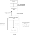
- FIG. 3 is a schematic diagram of a calibration site according to an embodiment of this application.
- the calibration site in FIG. 3 is used, for example, to calibrate a sensing apparatus such as a camera or a radar installed on the vehicle 1.
- a sensing apparatus such as a camera or a radar installed on the vehicle 1.
- a calibration site with a length L and a width B a plurality of calibration boards 2 are disposed on two sides, and an interval between the two calibration boards 2 is d.
- the camera and radar sensing calibration board 2 installed on the vehicle 1 collect sensing data of the camera and radar as traveling data, and calibrate parameters of the camera and radar based on the traveling data.
- the camera calibration method may use a Zhang Zhengyou algorithm.
- the parameter of the camera includes an intrinsic parameter, an extrinsic parameter, and a distortion parameter.
- the parameter of the radar includes a rotation parameter and a translation parameter of the radar. The camera and radar may also be calibrated together.
- the shape of the calibration site is not limited to the straight line in FIG. 3 , and may also be a curve shape based on a specific calibration requirement.
- a manner of setting the calibration board 2 is not limited to the manner in FIG. 3 . For example, it may be set that distances between every two calibration boards 2 are different.
- the calibration board 2 is, for example, an AprilTag (a visual positioning symbol) or a checkerboard calibration board.
- the AprilTag calibration board may use Tag16h5, Tag25h9, Tag36h11, or other types.
- a vehicle For a process of collecting traveling data in the calibration site shown in FIG. 3 , there is usually a specific requirement, mainly including requirements on a traveling trajectory and a traveling speed of a vehicle during data collection.
- a vehicle is usually required to travel at a designed speed based on a collection trajectory R.
- quality of collected traveling data is not high, and a collection speed is slow. Consequently, calibration quality is poor, and calibration efficiency is low.
- this application proposes an autonomous vehicle calibration method based on VIL (Vehicle in Loop, vehicle in loop)/MOP (Motion Planning, motion planning) processing, and collecting traveling data with high quality and quickly in an automated manner.
- VIL is a simulation test that embeds a complete vehicle system into a simulation loop. It can also be understood as a virtual-real combination method that combines a simulation test and a real vehicle test.
- VIL/MOP processing in combination of the VIL and the MOP is used to control the vehicle 1 to automatically travel in the calibration site according to a requirement, so as to implement automatic collection of traveling data.
- the motion planning module 15 of the control apparatus 10 of the vehicle 1 obtains pre-stored designed trajectory information, where the designed trajectory information indicates a designed traveling trajectory of the vehicle.
- the pre-stored designed trajectory information includes coordinate information of a plurality of trajectory points on the designed traveling trajectory in a vehicle coordinate system.
- the motion planning module 15 obtains pre-stored reference point information, where the reference point information includes world coordinates of at least one reference point.
- the reference point is a point on the designed traveling trajectory.
- the reference point information may further include a designed course angle of the vehicle at the reference point.
- the motion planning module 15 converts, based on the reference point information, coordinates of the plurality of the trajectory points on the designed traveling trajectory into world coordinates through coordinate conversion, to obtain a traveling trajectory ("collection trajectory" for short) of the vehicle in the calibration site for collecting traveling data. Then, the motion planning module 15 plans a planning trajectory of the vehicle 1 in the calibration site based on the positioning information of the vehicle 1.
- the planning trajectory includes a collection trajectory and a start trajectory, and the start trajectory is used to enable the vehicle 1 to automatically travel from a current position to a start point of the collection trajectory.
- the collection calibration module 16 starts to collect traveling data, where the traveling data is used to calibrate a calibration object of the vehicle.
- the collection start position corresponds to a preset position on the designed traveling trajectory.
- the collection start position may correspond to a start point of the designed traveling trajectory. That is, the collection start position may be, for example, a start point of the collection trajectory.
- the calibration object includes apparatuses at the perception layer such as the camera and the radar, apparatuses at the execution layer such as the braking system, the steering system, and the power system, and the basic ADAS functions at the function layer.
- the traveling data is, for example, a shot image obtained by the camera photographing a target object (for example, a calibration board 20 in FIG. 3 ) that is set at a specified position in the calibration site.
- the traveling data is, for example, radar raw data (raw data) obtained by sensing the target object by the radar.
- FIG. 4 is a schematic diagram of a VIL/MOP processing principle according to an embodiment of this application.
- a pre-stored MOP file is loaded to an MOP injection node, and MOP injection node initialization loading is performed.
- the MOP injection node is a motion planning module 15 of a control apparatus 10.
- a dedicated function module may be set in the control apparatus 10, to implement a function of the MOP injection node.
- the MOP file is stored, for example, in a memory of the control apparatus 10, but is not limited thereto.
- the MOP file includes, for example, designed trajectory information and designed speed information.
- the designed trajectory information is information about a designed traveling trajectory of the vehicle 1 designed according to a calibration requirement.
- the designed trajectory information is a formula or a point set in a vehicle coordinate system. That is, a position of a point on the designed traveling trajectory is defined by coordinates in the vehicle coordinate system.
- the vehicle coordinate system is used to describe a relative position relationship between an object around the vehicle and the vehicle, and the vehicle coordinate system can be used to describe a vehicle body posture.
- the vehicle coordinate system uses a rectangular coordinate system defined by SAE (Society of Automotive Engineers, society of automotive engineers).
- a rectangular coordinate system defined by an ISO (International Organization for Standardization, international organization for standardization) or an IMU-based rectangular coordinate system may also be used.
- the designed speed information is information about a designed traveling speed of the vehicle 1 on the designed traveling trajectory.
- the designed traveling trajectory and the designed driving speed may be freely designed based on the calibration requirement.
- the designed traveling trajectory may be a curve shape, a straight line shape, or a shape of a combination of a straight line and a curve.
- the designed traveling speed may be that the vehicle 1 keeps a constant speed on the designed traveling trajectory, or may be that different traveling speeds are designed for different parts on the designed traveling trajectory.
- the designed traveling trajectory and the designed traveling speed information in the MOP file may be obtained through forward design, or may be obtained in a manual teaching manner.
- the manual teaching manner means that a vehicle is manually driven in a calibration site to demonstrate a trajectory and a speed when data is collected, and a traveling trajectory and a traveling speed at this time are recorded as a designed traveling trajectory and a designed traveling speed.
- the motion planning module 15 used as the MOP injection node converts, based on pre-stored reference point information, coordinates of all points on the designed traveling trajectory into world coordinates.
- the reference point information includes world coordinates of the reference point and a designed course angle of the vehicle 1 at the reference point.
- the designed course angle may indicate an included angle between a speed of a center of mass of the vehicle (that is, a traveling direction of the vehicle) and a coordinate axis of the world coordinate system in the world coordinate system. That is, the included angle between the vehicle coordinate system and the world coordinate system may be determined based on the designed course angle.
- the design course angle is designed based on the calibration site.
- the reference point includes a start point of the designed traveling trajectory.
- the reference point may not include the start point of the designed traveling trajectory, but includes at least one point other than the start point of the designed traveling trajectory.
- the reference point information may not include a designed course angle, but includes world coordinates of two points on the designed traveling trajectory. The included angle between the vehicle coordinate system and the world coordinate system is determined based on the world coordinates of the two points.
- the world coordinate system uses a UTM (Universal Transverse Mercator Grid System, universal transversal mercator grid system) coordinate system.
- UTM Universal Transverse Mercator Grid System, universal transversal mercator grid system
- wgs-84 coordinate system World Geodetic System-1984 Coordinate System
- FIG. 5 is a schematic diagram of a coordinate conversion method according to an embodiment of this application.
- coordinates of a reference point O1 in the world coordinate system are (x0,y0)
- coordinates of a trajectory point A on the designed traveling trajectory in the vehicle coordinate system are (x,y)
- an included angle between the vehicle coordinate system and the world coordinate system is ⁇ .
- the coordinates (x',y') of the trajectory point A in the world coordinate system may be calculated based on the following formula.
- x ′ cos ⁇ ⁇ x + sin ⁇ ⁇ y + x0
- y ′ cos ⁇ ⁇ y ⁇ sin ⁇ ⁇ x + y0
- the motion planning module 15 used as an MOP injection node obtains current position information of the vehicle from a positioning module 18 used as the positioning node, and obtains planning trajectory of the vehicle 1 in the calibration site through planning based on the current position of the vehicle and the designed traveling trajectory.
- the planning trajectory includes a collection trajectory corresponding to the designed traveling trajectory, and a start trajectory used to enable the vehicle 1 to automatically travel from a current position to a start point of the collection trajectory.
- a collection start position and a collection end position are set on the collection trajectory.
- the collection start position is a position at which the collection of the traveling data starts.
- the collection end position is a position at which the collection of the traveling data ends.
- the collection start position corresponds to the start point of the designed traveling trajectory
- the collection end position corresponds to the end point of the designed traveling trajectory.
- the collection start position and the collection end position may be preset in the designed trajectory information, and which point on the designed traveling trajectory is a collection start point or a collection end point corresponding to the collection start position or the collection end position; or may not be preset in the designed trajectory information, and the start point and the end point of the designed traveling trajectory are directly defaulted to correspond to the collection start position or the collection end position.
- the motion planning module 15 plans a speed and an acceleration of the vehicle 1 on the planning trajectory based on the designed speed information.
- a planning speed of the vehicle 1 on the collection trajectory in the planning trajectory needs to strictly comply with the designed speed information.
- the planning speed of the vehicle 1 on the start trajectory that is, the planning speed from the current position of the vehicle 1 to the start point of the collection trajectory, provided that the vehicle 1 can meet the requirement of the designed speed information when reaching the start point of the collection trajectory.
- the motion control module 17 used as the control node controls a motion behavior of the vehicle 1 based on a planning result, so that the vehicle 1 automatically travels based on the planning trajectory and speed.
- the motion control module 17 further controls a motion behavior of the vehicle 1 based on the obtained chassis information of the vehicle 1.
- the chassis information includes, for example, information such as a wheel speed, a steering angle, and a yaw rate.
- the positioning and control node is, for example, the positioning module 18 and the motion control module 17 that are of the control apparatus 10.
- the positioning and control node may alternatively be a module that has a related function and that is of a mobile data center (Mobile Data Center, MDC) used as an autonomous driving controller.
- MDC Mobile Data Center
- the positioning module 18 obtains information from the GNSS 50 and the IMU 60, and determines current position information of the vehicle 1 based on the obtained information.
- the current position information is provided to the motion planning module 15.
- the motion planning module 15 may perform real-time planning and adjustment on the trajectory and the speed of the vehicle 1 based on the current position information.
- FIG. 6 is a schematic flowchart of an autonomous vehicle calibration method based on VIL/MOP processing according to an embodiment of this application.
- the vehicle 1 may be driven by a driver to an initial position of a calibration site, or may be directly transported to an initial position of a calibration site after assembly is completed on a production assembly line.
- the control apparatus 10 starts to perform the method shown in FIG. 6 .
- the method includes steps S210 to S270.
- steps S210 to S270 With reference to the scenario in FIG. 3 , the following describes processing of steps S210 to S270 in detail.
- S210 Obtain designed trajectory information and designed speed information.
- the designed trajectory information and the designed speed information are included in a pre-stored MOP file, and the designed trajectory information includes coordinate information of a plurality of trajectory points on the designed traveling trajectory in a vehicle coordinate system.
- the MOP file may be, for example, pre-stored in a memory inside the vehicle 1, or may be obtained from an external device that is communicatively connected to the vehicle 1.
- a vehicle 1 is at an initial position Po of a calibration site, and designed trajectory information and designed speed information are obtained by obtaining the MOP file.
- S220 Perform coordinate conversion based on the world coordinates of the reference point. Based on the pre-stored world coordinates of the reference point, coordinates of all trajectory points on the designed traveling trajectory are converted into world coordinates by using the coordinate conversion method in FIG. 5 described above.
- the world coordinates of the reference point may be, for example, pre-stored in a memory inside the vehicle 1, or may be obtained from an external device that is communicatively connected to the vehicle 1.
- coordinate conversion is performed on the designed trajectory information based on the obtained world coordinates of a start point Ps to obtain the collection trajectory R.
- the collection start position is the start point Ps of the collection trajectory R
- the collection end position is an end point Pe of the collection trajectory R.
- the planning trajectory is generated based on the current position information of the vehicle 1, and the planning speed on the planning trajectory is generated based on the setting speed information.
- the generated planning trajectory includes a collection trajectory corresponding to the designed traveling trajectory, and a start trajectory from a current position of the vehicle 1 to a start point of the collection trajectory.
- an MOP route from an initial position Po to a collection start position Ps, and then from the collection start position Ps to a collection end position Pe along a collection trajectory R is set.
- the speed on the collection trajectory R is planned based on the designed speed information obtained in S210.
- real-time planning and adjustment may be performed on a trajectory and a speed that reach an end point of the MOP route based on a change of a current position in a driving process of the vehicle.
- the initial position Po and the collection start position Ps are different positions. A reason is that, by setting a specific preparation distance, the vehicle 1 reaches a specific speed at the collection start position Ps can be ensured. In this way, even if there is a special requirement such as that the vehicle 1 needs to keep a constant speed when the traveling data is collected, such a requirement can be met.
- the initial position Po is not a position on the collection trajectory R, and the traveling data has not been collected at the position, position precision of the vehicle 1 does not affect collection quality of the traveling data in this case. Therefore, when the vehicle 1 is set at an initial stage, the vehicle 1 only needs to be placed in a specific range centered on the initial position Po, instead of being set at the initial position Po.
- the vehicle 1 can automatically travel from the initial position Po or a position near the initial position Po to the collection start position Ps.
- S240 Send a control instruction used to enable the vehicle to automatically travel according to the MOP route. Based on the set MOP route, a control instruction used to send to the power system 70, the steering system 80, the braking system 90, and the like of the vehicle 1 is generated. The power system 70, the steering system 80, the braking system 90, and the like execute the control instruction, so that the vehicle 1 automatically travels according to the MOP route.
- S250 Determine whether a current position of the vehicle 1 is a collection start position.
- current position information of the vehicle 1 is obtained based on IMU information, GNSS information, and the like, and whether the vehicle 1 reaches a collection start position Ps is determined. If the vehicle 1 reaches the collection start position Ps, perform S260; or if the vehicle 1 does not reach the collection start position Ps, perform S270.
- the traveling data is, for example, an image captured by photographing the calibration board 2 by the camera, or radar raw data obtained by the radar sensing calibration board 2.
- the obtained traveling data may be used to perform online calibration on calibration objects such as a camera and a radar, and a calibration result is directly output, but this is not limited thereto.
- the obtained traveling data may be further stored, and calibrated later.
- the calibration result may also be uploaded to the management platform by using a communication connection to an external management platform, and the management platform uniformly manages information of a plurality of vehicles.
- the processing in this step may also be replaced with starting the calibration mode.
- S270 Determine whether the vehicle reaches an end point or is taken over by the driver. If the vehicle reaches the end point or is taken over by the driver, the process ends; or if the vehicle does not reach the end point or is not taken over by the driver, the process returns to S230.
- the end point herein may be, for example, a collection end position Pe on the collection trajectory R. When the vehicle has reached the collection end position Pe or has been taken over by the driver, the process ends, which may also be understood as ending the collection of the traveling data or ending the calibration mode. In some embodiments, before the process is ended, whether the calibration is successful is determined, and a determining result of successful/failed calibration is recorded.
- the vehicle 1 automatically travels from the collection start position Ps to the collection end position Pe based on the pre-designed traveling trajectory and traveling speed, and collects traveling data.
- autonomous driving can accurately perform horizontal and vertical trajectory tracking control on the vehicle. Therefore, quality of the collected traveling data can be improved, and calibration precision can be improved.
- data required for calibration may be collected by using a relatively short designed traveling trajectory. Specifically, for example, in the scenario in FIG. 3 , a designed traveling trajectory of about 70 meters is required in the prior art.
- calibration of a camera and a radar may be completed by using a designed traveling trajectory of about 50 meters, which is actually equivalent to improving a data collection speed.
- an unmanned operation can be implemented in an entire calibration process, and an all-weather collection operation can be implemented, so that a data collection speed is improved while a calibration success rate is improved by reducing interference caused by human driving, thereby better meeting the demand of mass production scale of the vehicles.
- the pre-stored designed trajectory information may also be coordinate information of a point on the designed traveling trajectory in a world coordinate system. In this case, coordinate conversion processing may be omitted.
- the pre-stored designed trajectory information is coordinate information in a vehicle coordinate system
- the same designed traveling trajectory can be automatically mapped to the calibration sites of the different locations by changing the reference point information, and an MOP file does not need to be separately designed for each calibration site. Therefore, a design workload can be reduced.
- the collection start position may not correspond to the start point of the designed traveling trajectory, but corresponds to another point on the designed traveling trajectory.
- the collection end position may not correspond to the end point of the designed traveling trajectory, but corresponds to another point on the designed traveling trajectory.
- FIG. 3 schematically lists an example in which the collection trajectory R is in a straight line shape when the traveling data used to calibrate the camera and the radar is collected.
- the collection trajectory R may also be in a curve shape.
- the shape of the collection trajectory R may be designed based on a specific calibration requirement. For example, when the traveling data of the steering system used to calibrate the execution layer is collected, the collection trajectory R may be a curve.
- traveling data such as GNSS data, INS data, and a wheel speed, a yaw rate, and a steering wheel angle that are of the vehicle 1 may be collected at the same time, and the data is centrally stored. Timestamps are added to all collected data.
- processing such as interpolation compensation may be performed on data with different sampling frequencies based on the timestamp, to ensure time synchronization of various data. In this way, efficient collection of integrated comprehensive data can be implemented.
- a trajectory tracking process of the vehicle 1 may be further visualized, and displayed on a display screen of a mobile terminal held by a vehicle-mounted display apparatus, a management platform, or a calibration engineer.
- the planning trajectory shown by the thick solid line and information such as the current position and orientation of the vehicle 1 may be displayed on the display screen, so as to determine whether the vehicle 1 deviates from the planning trajectory.
- a virtual lane line shown by a thin solid line, a virtual lane center line shown by a dashed line, and the like may be further displayed.
- FIG. 9 is a schematic diagram of a structure of an autonomous vehicle calibration apparatus according to an embodiment of this application.
- the calibration apparatus may be a vehicle-mounted terminal, or may be a chip or a chip system inside the vehicle-mounted terminal, and may implement the autonomous vehicle calibration method and the optional embodiments that are described with reference to FIG. 1 to FIG. 8 .
- the calibration apparatus 1000 includes an obtaining module 1100 and a processing module 1200.
- the obtaining module 1100 is configured to obtain first trajectory information.
- the obtaining module 1100 is further configured to obtain position information of a vehicle.
- the processing module 1200 is configured to generate a planning trajectory based on the first trajectory information and the position information of the vehicle that are obtained by the obtaining module 1100.
- the processing module 1200 is further configured to: when the vehicle automatically travels to a first position along the generated planning trajectory, start to collect traveling data.
- the first position corresponds to a preset position on a first trajectory indicated by the first trajectory information.
- the processing module 1200 is further configured to: convert the first trajectory information into second trajectory information that is in a world coordinate system, and generate a planning trajectory based on the second trajectory information and the position information of the vehicle.
- the obtaining module 1100 may obtain first coordinate information, where the first coordinate information indicates coordinates of the preset position in the world coordinate system; and the processing module 1200 converts, based on the first coordinate information obtained by the obtaining module 1100, the first trajectory information into the second trajectory information that is in the world coordinate system.
- the calibration apparatus in this embodiment of this application may be implemented by software, for example, implemented by a computer program or an instruction having the foregoing functions.
- a corresponding computer program or instruction may be stored in a memory in a vehicle-mounted terminal, and the processor reads the corresponding computer program or instruction in the memory to implement the foregoing functions.
- the calibration apparatus in this embodiment of this application may be implemented by hardware.
- the processing module 1200 is a processor, and the obtaining module 1100 is a transceiver circuit or an interface circuit.
- the calibration apparatus in this embodiment of this application may be implemented by a combination of a processor and a software module.
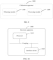
- FIG. 10 is a schematic diagram of a structure of an electronic apparatus according to an embodiment of this application.
- the electronic apparatus may be used as an autonomous vehicle calibration apparatus, to perform the autonomous vehicle calibration method and optional embodiments described with reference to FIG. 1 to FIG. 8 .
- the electronic apparatus may be a vehicle-mounted terminal, or may be a chip or a chip system inside the vehicle-mounted terminal.
- the electronic apparatus 1600 includes: a processor 1610, and an interface circuit 1620 coupled to the processor 1610. It should be understood that, although FIG. 10 shows only one processor and one interface circuit, the electronic apparatus 1600 may include another quantity of processors and interface circuits.
- the interface circuit 1620 is configured to communicate with another component of the terminal, for example, a memory or another processor.
- the processor 1610 is configured to perform signal interaction with another component by using the interface circuit 1620.
- the interface circuit 1620 may be an input/output interface of the processor 1610.
- the processor 1610 reads, by using the interface circuit 1620, computer programs or instructions in the memory coupled to the interface circuit 1620, and decodes and executes the computer programs or instructions.
- the computer programs or instructions may include the foregoing terminal function program, or may include the foregoing function program of the calibration apparatus applied in the terminal.
- the vehicle-mounted terminal or the calibration apparatus in the vehicle-mounted terminal may be enabled to implement the solution in the autonomous vehicle calibration method provided in the embodiments of this application.
- these terminal function programs are stored in a memory outside the electronic apparatus 1600.
- the terminal function programs are decoded and executed by the processor 1600, some or all content of the terminal function programs is temporarily stored in the memory.
- these terminal function programs are stored in a memory inside the electronic apparatus 1600.
- the electronic apparatus 1600 may be set in the terminal of the embodiment of the present invention.
- some content of the terminal function programs is stored in a memory outside the electronic apparatus 1800, and other content of the terminal function programs is stored in a memory inside the electronic apparatus 1800.
- the disclosed system, apparatus, and method may be implemented in other manners.
- the described apparatus embodiment is merely an example.
- division into the units is merely logical function division and may be other division in actual implementation.
- a plurality of units or components may be combined or integrated into another system, or some features may be ignored or not performed.
- the displayed or discussed mutual couplings or direct couplings or communication connections may be implemented by using some interfaces.
- the indirect couplings or communication connections between the apparatuses or units may be implemented in electronic, mechanical, or other forms.
- the units described as separate parts may or may not be physically separate, and parts displayed as units may or may not be physical units, may be located in one position, or may be distributed on a plurality of network units. Some or all of the units may be selected according to actual requirements to achieve the objectives of embodiments of this application.
- the functions When the functions are implemented in a form of a software functional unit and sold or used as an independent product, the functions may be stored in a computer-readable storage medium. Based on such an understanding, the technical solutions of this application essentially, or the part contributing to the conventional technology, or some of the technical solutions may be implemented in a form of a software product.
- the computer software product is stored in a storage medium, and includes several instructions for instructing a computer device (which may be a personal computer, a server, or a network device) to perform all or some of the steps of the methods described in embodiments of this application.
- the foregoing storage medium includes any medium that can store program code, such as a USB flash drive, a removable hard disk, a read-only memory (Read-Only Memory, ROM), a random access memory (Random Access Memory, RAM), a magnetic disk, or an optical disc.
- program code such as a USB flash drive, a removable hard disk, a read-only memory (Read-Only Memory, ROM), a random access memory (Random Access Memory, RAM), a magnetic disk, or an optical disc.
- An embodiment of this application further provides a computer-readable storage medium.
- the computer-readable storage medium stores a computer program. When being executed by a processor, the program is used to perform at least one of the solutions described in the foregoing embodiments.
- the computer storage medium in this embodiment of this application may be any combination of one or more computer-readable media.
- the computer-readable medium may be a computer-readable signal medium or a computer-readable storage medium.
- the computer-readable storage medium may be, but is not limited to, an electric, magnetic, optical, electromagnetic, infrared, or semiconductor system, apparatus, or device, or any combination thereof.
- the computer-readable storage medium includes: an electrical connection having one or more wires, a portable computer disk, a hard disk, a random access memory (RAM), a read-only memory (ROM), an erasable programmable read-only memory (EPROM, Erasable Programmable Read Only Memory, or flash memory), an optical fiber, a portable compact disc read-only memory (CD-ROM), an optical storage device, a magnetic storage device, or any suitable combination thereof.
- the computer-readable storage medium may be any tangible medium that includes or stores a program, and the program may be used by or in combination with an instruction execution system, apparatus, or device.
- the computer-readable signal medium may include a data signal that is propagated in a baseband or propagated as part of a carrier, where the data signal carries computer-readable program code. Such a propagated data signal may be in a plurality of forms, including but not limited to, an electromagnetic signal, an optical signal, or any suitable combination thereof.
- the computer-readable signal medium may alternatively be any computer-readable medium other than the computer-readable storage medium.
- the computer-readable medium may send, propagate, or transmit a program used by or in combination with an instruction execution system, apparatus, or device.
- Program code included in the computer-readable medium may be transmitted by using any proper medium, including but not limited to wireless, electric wire, optical cable, RF (Radio Frequency, radio frequency), or any suitable combination thereof.
- Computer program code used to perform operations in this application may be written in one or more program design languages or a combination thereof.
- the program design language includes an object-oriented program design language such as Java, Smalltalk, and C++, and further includes a conventional procedural program design language such as a "C" language or a similar program design language.
- the program code may be executed entirely on a user computer, or some may be executed on a user computer as a separate software package, or some may be executed on a user computer while some is executed on a remote computer, or the code may be entirely executed on a remote computer or a server.
- the remote computer may be connected to a user computer through any type of network, including a wireless local area network (LAN, Wireless Local Area Network) or a wide area network (WAN, Wide Area Network), or may be connected to an external computer (for example, through the Internet provided by an Internet service provider).
- LAN wireless local area network
- WAN wide area network
Landscapes
- Engineering & Computer Science (AREA)
- Radar, Positioning & Navigation (AREA)
- Remote Sensing (AREA)
- Physics & Mathematics (AREA)
- General Physics & Mathematics (AREA)
- Computer Networks & Wireless Communication (AREA)
- Automation & Control Theory (AREA)
- Human Computer Interaction (AREA)
- Transportation (AREA)
- Mechanical Engineering (AREA)
- Manufacturing & Machinery (AREA)
- Electromagnetism (AREA)
- Traffic Control Systems (AREA)
Applications Claiming Priority (1)
| Application Number | Priority Date | Filing Date | Title |
|---|---|---|---|
| PCT/CN2021/100139 WO2022261825A1 (fr) | 2021-06-15 | 2021-06-15 | Procédé et dispositif d'étalonnage pour véhicule à conduite automatique |
Publications (3)
| Publication Number | Publication Date |
|---|---|
| EP4343370A1 true EP4343370A1 (fr) | 2024-03-27 |
| EP4343370A4 EP4343370A4 (fr) | 2024-06-19 |
| EP4343370B1 EP4343370B1 (fr) | 2025-10-22 |
Family
ID=82422616
Family Applications (1)
| Application Number | Title | Priority Date | Filing Date |
|---|---|---|---|
| EP21945418.8A Active EP4343370B1 (fr) | 2021-06-15 | 2021-06-15 | Procédé et dispositif d'étalonnage pour véhicule à conduite automatique |
Country Status (3)
| Country | Link |
|---|---|
| EP (1) | EP4343370B1 (fr) |
| CN (1) | CN114787015B (fr) |
| WO (1) | WO2022261825A1 (fr) |
Families Citing this family (14)
| Publication number | Priority date | Publication date | Assignee | Title |
|---|---|---|---|---|
| CN115027505B (zh) * | 2022-07-28 | 2023-10-31 | 广州小鹏自动驾驶科技有限公司 | 车辆的轨迹重规划方法、装置、系统、车辆及存储介质 |
| CN116295508A (zh) * | 2022-09-07 | 2023-06-23 | 北京宾理信息科技有限公司 | 一种基于高精地图的路侧传感器标定方法、设备和系统 |
| CN115431995B (zh) * | 2022-10-18 | 2023-12-22 | 广州万协通信息技术有限公司 | 基于不同级别辅助驾驶的设备控制方法及装置 |
| CN116086515A (zh) * | 2022-12-20 | 2023-05-09 | 北京汽车股份有限公司 | 汽车传感器动态标定方法及系统 |
| CN116358601B (zh) * | 2023-03-29 | 2025-08-05 | 重庆长安汽车股份有限公司 | 自动驾驶定位校准方法、装置、系统、车辆和存储介质 |
| US12576861B2 (en) | 2023-08-16 | 2026-03-17 | Shanghai Tosun Technology Ltd. | Vehicle calibration system and vehicular development and debugging system |
| US12482309B2 (en) | 2023-08-16 | 2025-11-25 | Shanghai Tosun Technology Ltd. | Automatic reading and writing method of vehicular calibration signal and vehicle calibration method |
| CN117036505B (zh) * | 2023-08-23 | 2024-03-29 | 长和有盈电子科技(深圳)有限公司 | 车载摄像头在线标定方法及系统 |
| CN117076734B (zh) * | 2023-08-30 | 2025-09-30 | 广西玉柴机器股份有限公司 | 一种电控数据自动集成方法及数据库、系统 |
| CN117433539B (zh) * | 2023-12-20 | 2024-06-11 | 中国汽车技术研究中心有限公司 | 一种汽车场地测试多目标物协同轨迹规划的方法及装置 |
| CN118094904A (zh) * | 2024-02-22 | 2024-05-28 | 北京集度科技有限公司 | 联合仿真方法、装置、电子设备和存储介质 |
| CN119559607B (zh) * | 2024-10-09 | 2026-01-09 | 深圳鼎匠科技有限公司 | 基于双目相机的车辆中线查找与校准方法及装置 |
| CN119996838A (zh) * | 2025-01-10 | 2025-05-13 | 北京四维远见信息技术有限公司 | 一种基于规划路线的车载绿视率采集控制方法及系统 |
| CN120352163B (zh) * | 2025-06-24 | 2025-09-09 | 睿羿科技(山东)有限公司 | 一种室外无人清扫车自适应转向标定方法 |
Family Cites Families (16)
| Publication number | Priority date | Publication date | Assignee | Title |
|---|---|---|---|---|
| JP2017182521A (ja) * | 2016-03-31 | 2017-10-05 | 日立オートモティブシステムズ株式会社 | 車両用走行制御装置 |
| CN106981082B (zh) * | 2017-03-08 | 2020-04-17 | 驭势科技(北京)有限公司 | 车载摄像头标定方法、装置及车载设备 |
| CN109211298B (zh) * | 2017-07-04 | 2021-08-17 | 百度在线网络技术(北京)有限公司 | 一种传感器标定方法和装置 |
| US10678247B2 (en) * | 2017-08-28 | 2020-06-09 | GM Global Technology Operations LLC | Method and apparatus for monitoring of an autonomous vehicle |
| US10990101B2 (en) * | 2018-04-18 | 2021-04-27 | Baidu Usa Llc | Method for drifting correction for planning a path for autonomous driving vehicles |
| EP3659004B1 (fr) * | 2018-05-18 | 2021-07-07 | Baidu.com Times Technology (Beijing) Co., Ltd. | Correction de dérive entre un étage de planification et un étage de commande de véhicules à conduite autonome en fonctionnement |
| CN109084794B (zh) * | 2018-08-09 | 2021-05-07 | 北京智行者科技有限公司 | 一种路径规划方法 |
| CN109343061B (zh) * | 2018-09-19 | 2021-04-02 | 百度在线网络技术(北京)有限公司 | 传感器标定方法、装置、计算机设备、介质和车辆 |
| US11841437B2 (en) * | 2018-10-12 | 2023-12-12 | Baidu Usa Llc | Automatic lidar calibration based on pre-collected static reflection map for autonomous driving |
| JP2020093730A (ja) * | 2018-12-14 | 2020-06-18 | トヨタ自動車株式会社 | 車両走行制御装置 |
| CN109901139B (zh) * | 2018-12-28 | 2023-07-04 | 文远知行有限公司 | 激光雷达标定方法、装置、设备和存储介质 |
| CN109541571B (zh) * | 2018-12-29 | 2021-05-07 | 北京智行者科技有限公司 | Eps零偏和多线激光雷达的联合标定方法 |
| CN111169469B (zh) * | 2019-10-08 | 2021-03-12 | 中国第一汽车股份有限公司 | 一种车辆的轨迹规划方法、装置、存储介质及汽车 |
| CN111077506B (zh) * | 2019-12-12 | 2022-04-19 | 苏州智加科技有限公司 | 对毫米波雷达进行标定的方法、装置及系统 |
| CN112009460B (zh) * | 2020-09-03 | 2022-03-25 | 中国第一汽车股份有限公司 | 一种车辆控制方法、装置、设备及存储介质 |
| CN112146682B (zh) * | 2020-09-22 | 2022-07-19 | 福建牧月科技有限公司 | 智能汽车的传感器标定方法、装置、电子设备及介质 |
-
2021
- 2021-06-15 CN CN202180006787.0A patent/CN114787015B/zh active Active
- 2021-06-15 WO PCT/CN2021/100139 patent/WO2022261825A1/fr not_active Ceased
- 2021-06-15 EP EP21945418.8A patent/EP4343370B1/fr active Active
Also Published As
| Publication number | Publication date |
|---|---|
| EP4343370B1 (fr) | 2025-10-22 |
| CN114787015A (zh) | 2022-07-22 |
| WO2022261825A1 (fr) | 2022-12-22 |
| CN114787015B (zh) | 2025-08-08 |
| EP4343370A4 (fr) | 2024-06-19 |
Similar Documents
| Publication | Publication Date | Title |
|---|---|---|
| EP4343370B1 (fr) | Procédé et dispositif d'étalonnage pour véhicule à conduite automatique | |
| EP3943983A1 (fr) | Méthode, dispositif, support et équipement de positionnement | |
| CN112640332B (zh) | 一种通信方法及装置 | |
| US10810807B2 (en) | Data collection system and data center | |
| CN111559383A (zh) | 用于基于车辆和边缘传感器数据确定自主车辆(av)动作的方法和系统 | |
| WO2019225268A1 (fr) | Dispositif de génération de plan de déplacement, procédé de génération de plan de déplacement, et programme de commande | |
| CN111443327A (zh) | 保持车辆位置准确 | |
| CN115151466B (zh) | 行驶辅助装置、行驶辅助方法以及存储装置 | |
| CN113479195A (zh) | 用于自动代客泊车的方法和用于执行所述方法的系统 | |
| CN115314526B (zh) | 用于自车位置识别的系统架构、传输方法、车辆、介质及芯片 | |
| CN115330923B (zh) | 点云数据渲染方法、装置、车辆、可读存储介质及芯片 | |
| CN111044069B (zh) | 一种车辆定位方法、车载设备及存储介质 | |
| CN115320583B (zh) | 目标障碍车确定方法、装置、车辆及介质 | |
| US12434696B2 (en) | Trajectory generation device, trajectory generation method, and computer program product | |
| JP7452494B2 (ja) | 走行位置決定装置、走行位置決定方法、および走行位置決定プログラム | |
| CN115221151B (zh) | 车辆数据的传输方法、装置、车辆、存储介质及芯片 | |
| JP2019008424A (ja) | 情報処理装置及びプログラム | |
| US12552455B2 (en) | Systems and methods for calibrating a vehicle steering angle by leveraging a steering pinion angle offset and a wheel alignment funnel | |
| CN116420179A (zh) | 通信控制装置、通信控制方法以及通信控制程序 | |
| JP7355074B2 (ja) | 制御装置、制御方法、および制御プログラム | |
| CN115123304B (zh) | 故障追踪方法、装置、介质及芯片 | |
| CN115334113B (zh) | 用于道路标识识别的系统架构、传输方法、车辆、介质及芯片 | |
| CN118150196A (zh) | 用于校准车辆转向角的系统和方法 | |
| CN114003025B (zh) | 一种运动控制方法及装置 | |
| WO2023085062A1 (fr) | Dispositif de commande, système de commande, procédé de commande et programme de commande |
Legal Events
| Date | Code | Title | Description |
|---|---|---|---|
| STAA | Information on the status of an ep patent application or granted ep patent |
Free format text: STATUS: THE INTERNATIONAL PUBLICATION HAS BEEN MADE |
|
| PUAI | Public reference made under article 153(3) epc to a published international application that has entered the european phase |
Free format text: ORIGINAL CODE: 0009012 |
|
| STAA | Information on the status of an ep patent application or granted ep patent |
Free format text: STATUS: REQUEST FOR EXAMINATION WAS MADE |
|
| 17P | Request for examination filed |
Effective date: 20231218 |
|
| AK | Designated contracting states |
Kind code of ref document: A1 Designated state(s): AL AT BE BG CH CY CZ DE DK EE ES FI FR GB GR HR HU IE IS IT LI LT LU LV MC MK MT NL NO PL PT RO RS SE SI SK SM TR |
|
| A4 | Supplementary search report drawn up and despatched |
Effective date: 20240517 |
|
| RIC1 | Information provided on ipc code assigned before grant |
Ipc: G01C 21/30 20060101ALI20240513BHEP Ipc: G01C 25/00 20060101ALI20240513BHEP Ipc: G01S 7/40 20060101AFI20240513BHEP |
|
| DAV | Request for validation of the european patent (deleted) | ||
| DAX | Request for extension of the european patent (deleted) | ||
| RAP1 | Party data changed (applicant data changed or rights of an application transferred) |
Owner name: SHENZHEN YINWANG INTELLIGENTTECHNOLOGIES CO., LTD. |
|
| GRAP | Despatch of communication of intention to grant a patent |
Free format text: ORIGINAL CODE: EPIDOSNIGR1 |
|
| STAA | Information on the status of an ep patent application or granted ep patent |
Free format text: STATUS: GRANT OF PATENT IS INTENDED |
|
| RIC1 | Information provided on ipc code assigned before grant |
Ipc: G01S 13/931 20200101ALI20250502BHEP Ipc: G01S 13/86 20060101ALI20250502BHEP Ipc: G01S 7/497 20060101ALI20250502BHEP Ipc: B60W 60/00 20200101ALI20250502BHEP Ipc: G01C 21/30 20060101ALI20250502BHEP Ipc: G01C 25/00 20060101ALI20250502BHEP Ipc: G01S 7/40 20060101AFI20250502BHEP |
|
| INTG | Intention to grant announced |
Effective date: 20250520 |
|
| GRAS | Grant fee paid |
Free format text: ORIGINAL CODE: EPIDOSNIGR3 |
|
| GRAA | (expected) grant |
Free format text: ORIGINAL CODE: 0009210 |
|
| STAA | Information on the status of an ep patent application or granted ep patent |
Free format text: STATUS: THE PATENT HAS BEEN GRANTED |
|
| AK | Designated contracting states |
Kind code of ref document: B1 Designated state(s): AL AT BE BG CH CY CZ DE DK EE ES FI FR GB GR HR HU IE IS IT LI LT LU LV MC MK MT NL NO PL PT RO RS SE SI SK SM TR |
|
| REG | Reference to a national code |
Ref country code: CH Ref legal event code: F10 Free format text: ST27 STATUS EVENT CODE: U-0-0-F10-F00 (AS PROVIDED BY THE NATIONAL OFFICE) Effective date: 20251022 Ref country code: GB Ref legal event code: FG4D |
|
| P01 | Opt-out of the competence of the unified patent court (upc) registered |
Free format text: CASE NUMBER: UPC_APP_8376_4343370/2025 Effective date: 20250930 |
|
| REG | Reference to a national code |
Ref country code: DE Ref legal event code: R096 Ref document number: 602021041078 Country of ref document: DE |
|
| REG | Reference to a national code |
Ref country code: IE Ref legal event code: FG4D |
|
| REG | Reference to a national code |
Ref country code: NL Ref legal event code: MP Effective date: 20251022 |
|
| PG25 | Lapsed in a contracting state [announced via postgrant information from national office to epo] |
Ref country code: NL Free format text: LAPSE BECAUSE OF FAILURE TO SUBMIT A TRANSLATION OF THE DESCRIPTION OR TO PAY THE FEE WITHIN THE PRESCRIBED TIME-LIMIT Effective date: 20251022 |
|
| PG25 | Lapsed in a contracting state [announced via postgrant information from national office to epo] |
Ref country code: ES Free format text: LAPSE BECAUSE OF FAILURE TO SUBMIT A TRANSLATION OF THE DESCRIPTION OR TO PAY THE FEE WITHIN THE PRESCRIBED TIME-LIMIT Effective date: 20251022 |
|
| REG | Reference to a national code |
Ref country code: LT Ref legal event code: MG9D |
|
| PG25 | Lapsed in a contracting state [announced via postgrant information from national office to epo] |
Ref country code: NO Free format text: LAPSE BECAUSE OF FAILURE TO SUBMIT A TRANSLATION OF THE DESCRIPTION OR TO PAY THE FEE WITHIN THE PRESCRIBED TIME-LIMIT Effective date: 20260122 |
|
| PG25 | Lapsed in a contracting state [announced via postgrant information from national office to epo] |
Ref country code: HR Free format text: LAPSE BECAUSE OF FAILURE TO SUBMIT A TRANSLATION OF THE DESCRIPTION OR TO PAY THE FEE WITHIN THE PRESCRIBED TIME-LIMIT Effective date: 20251022 Ref country code: AT Free format text: LAPSE BECAUSE OF FAILURE TO SUBMIT A TRANSLATION OF THE DESCRIPTION OR TO PAY THE FEE WITHIN THE PRESCRIBED TIME-LIMIT Effective date: 20251022 Ref country code: FI Free format text: LAPSE BECAUSE OF FAILURE TO SUBMIT A TRANSLATION OF THE DESCRIPTION OR TO PAY THE FEE WITHIN THE PRESCRIBED TIME-LIMIT Effective date: 20251022 |
|
| REG | Reference to a national code |
Ref country code: AT Ref legal event code: MK05 Ref document number: 1849577 Country of ref document: AT Kind code of ref document: T Effective date: 20251022 |
|
| PG25 | Lapsed in a contracting state [announced via postgrant information from national office to epo] |
Ref country code: RS Free format text: LAPSE BECAUSE OF FAILURE TO SUBMIT A TRANSLATION OF THE DESCRIPTION OR TO PAY THE FEE WITHIN THE PRESCRIBED TIME-LIMIT Effective date: 20260122 |
|
| PG25 | Lapsed in a contracting state [announced via postgrant information from national office to epo] |
Ref country code: IS Free format text: LAPSE BECAUSE OF FAILURE TO SUBMIT A TRANSLATION OF THE DESCRIPTION OR TO PAY THE FEE WITHIN THE PRESCRIBED TIME-LIMIT Effective date: 20260222 |
|
| PG25 | Lapsed in a contracting state [announced via postgrant information from national office to epo] |
Ref country code: PT Free format text: LAPSE BECAUSE OF FAILURE TO SUBMIT A TRANSLATION OF THE DESCRIPTION OR TO PAY THE FEE WITHIN THE PRESCRIBED TIME-LIMIT Effective date: 20260223 |
|
| PG25 | Lapsed in a contracting state [announced via postgrant information from national office to epo] |
Ref country code: PL Free format text: LAPSE BECAUSE OF FAILURE TO SUBMIT A TRANSLATION OF THE DESCRIPTION OR TO PAY THE FEE WITHIN THE PRESCRIBED TIME-LIMIT Effective date: 20251022 |
|
| PG25 | Lapsed in a contracting state [announced via postgrant information from national office to epo] |
Ref country code: LV Free format text: LAPSE BECAUSE OF FAILURE TO SUBMIT A TRANSLATION OF THE DESCRIPTION OR TO PAY THE FEE WITHIN THE PRESCRIBED TIME-LIMIT Effective date: 20251022 |