EP4343377A1 - Kommunikationsvorrichtung und entfernungsmessungsverfahren - Google Patents
Kommunikationsvorrichtung und entfernungsmessungsverfahren Download PDFInfo
- Publication number
- EP4343377A1 EP4343377A1 EP22804290.9A EP22804290A EP4343377A1 EP 4343377 A1 EP4343377 A1 EP 4343377A1 EP 22804290 A EP22804290 A EP 22804290A EP 4343377 A1 EP4343377 A1 EP 4343377A1
- Authority
- EP
- European Patent Office
- Prior art keywords
- frequency
- phase
- distance
- communication device
- change
- Prior art date
- Legal status (The legal status is an assumption and is not a legal conclusion. Google has not performed a legal analysis and makes no representation as to the accuracy of the status listed.)
- Pending
Links
- 238000000034 method Methods 0.000 title claims abstract description 206
- 238000004891 communication Methods 0.000 title claims abstract description 185
- 230000008859 change Effects 0.000 claims abstract description 324
- 238000004364 calculation method Methods 0.000 claims abstract description 96
- 230000008569 process Effects 0.000 claims description 116
- 230000001174 ascending effect Effects 0.000 claims description 96
- 230000033001 locomotion Effects 0.000 claims description 22
- 238000000691 measurement method Methods 0.000 claims description 21
- 238000005259 measurement Methods 0.000 abstract description 106
- 238000012545 processing Methods 0.000 description 25
- 238000010586 diagram Methods 0.000 description 23
- 239000003999 initiator Substances 0.000 description 19
- 238000005516 engineering process Methods 0.000 description 12
- 238000012986 modification Methods 0.000 description 12
- 230000004048 modification Effects 0.000 description 12
- 230000005540 biological transmission Effects 0.000 description 11
- 238000012935 Averaging Methods 0.000 description 10
- 230000004044 response Effects 0.000 description 10
- 230000001133 acceleration Effects 0.000 description 5
- 230000006870 function Effects 0.000 description 5
- 238000011156 evaluation Methods 0.000 description 4
- 230000000694 effects Effects 0.000 description 3
- 239000002131 composite material Substances 0.000 description 2
- 238000006073 displacement reaction Methods 0.000 description 2
- 230000007774 longterm Effects 0.000 description 2
- 230000010355 oscillation Effects 0.000 description 2
- NPOJQCVWMSKXDN-UHFFFAOYSA-N Dacthal Chemical compound COC(=O)C1=C(Cl)C(Cl)=C(C(=O)OC)C(Cl)=C1Cl NPOJQCVWMSKXDN-UHFFFAOYSA-N 0.000 description 1
- 238000013459 approach Methods 0.000 description 1
- 230000008901 benefit Effects 0.000 description 1
- 238000006243 chemical reaction Methods 0.000 description 1
- 238000012790 confirmation Methods 0.000 description 1
- 238000007796 conventional method Methods 0.000 description 1
- 230000006866 deterioration Effects 0.000 description 1
- 230000002542 deteriorative effect Effects 0.000 description 1
- 230000001151 other effect Effects 0.000 description 1
- 230000008054 signal transmission Effects 0.000 description 1
Images






Classifications
-
- G—PHYSICS
- G01—MEASURING; TESTING
- G01S—RADIO DIRECTION-FINDING; RADIO NAVIGATION; DETERMINING DISTANCE OR VELOCITY BY USE OF RADIO WAVES; LOCATING OR PRESENCE-DETECTING BY USE OF THE REFLECTION OR RERADIATION OF RADIO WAVES; ANALOGOUS ARRANGEMENTS USING OTHER WAVES
- G01S11/00—Systems for determining distance or velocity not using reflection or reradiation
- G01S11/02—Systems for determining distance or velocity not using reflection or reradiation using radio waves
-
- G—PHYSICS
- G01—MEASURING; TESTING
- G01S—RADIO DIRECTION-FINDING; RADIO NAVIGATION; DETERMINING DISTANCE OR VELOCITY BY USE OF RADIO WAVES; LOCATING OR PRESENCE-DETECTING BY USE OF THE REFLECTION OR RERADIATION OF RADIO WAVES; ANALOGOUS ARRANGEMENTS USING OTHER WAVES
- G01S7/00—Details of systems according to groups G01S13/00, G01S15/00, G01S17/00
- G01S7/003—Transmission of data between radar, sonar or lidar systems and remote stations
- G01S7/006—Transmission of data between radar, sonar or lidar systems and remote stations using shared front-end circuitry, e.g. antennas
-
- G—PHYSICS
- G01—MEASURING; TESTING
- G01S—RADIO DIRECTION-FINDING; RADIO NAVIGATION; DETERMINING DISTANCE OR VELOCITY BY USE OF RADIO WAVES; LOCATING OR PRESENCE-DETECTING BY USE OF THE REFLECTION OR RERADIATION OF RADIO WAVES; ANALOGOUS ARRANGEMENTS USING OTHER WAVES
- G01S13/00—Systems using the reflection or reradiation of radio waves, e.g. radar systems; Analogous systems using reflection or reradiation of waves whose nature or wavelength is irrelevant or unspecified
- G01S13/74—Systems using reradiation of radio waves, e.g. secondary radar systems; Analogous systems
- G01S13/82—Systems using reradiation of radio waves, e.g. secondary radar systems; Analogous systems wherein continuous-type signals are transmitted
- G01S13/825—Systems using reradiation of radio waves, e.g. secondary radar systems; Analogous systems wherein continuous-type signals are transmitted with exchange of information between interrogator and responder
-
- G—PHYSICS
- G01—MEASURING; TESTING
- G01S—RADIO DIRECTION-FINDING; RADIO NAVIGATION; DETERMINING DISTANCE OR VELOCITY BY USE OF RADIO WAVES; LOCATING OR PRESENCE-DETECTING BY USE OF THE REFLECTION OR RERADIATION OF RADIO WAVES; ANALOGOUS ARRANGEMENTS USING OTHER WAVES
- G01S13/00—Systems using the reflection or reradiation of radio waves, e.g. radar systems; Analogous systems using reflection or reradiation of waves whose nature or wavelength is irrelevant or unspecified
- G01S13/74—Systems using reradiation of radio waves, e.g. secondary radar systems; Analogous systems
- G01S13/82—Systems using reradiation of radio waves, e.g. secondary radar systems; Analogous systems wherein continuous-type signals are transmitted
- G01S13/84—Systems using reradiation of radio waves, e.g. secondary radar systems; Analogous systems wherein continuous-type signals are transmitted for distance determination by phase measurement
-
- G—PHYSICS
- G01—MEASURING; TESTING
- G01S—RADIO DIRECTION-FINDING; RADIO NAVIGATION; DETERMINING DISTANCE OR VELOCITY BY USE OF RADIO WAVES; LOCATING OR PRESENCE-DETECTING BY USE OF THE REFLECTION OR RERADIATION OF RADIO WAVES; ANALOGOUS ARRANGEMENTS USING OTHER WAVES
- G01S13/00—Systems using the reflection or reradiation of radio waves, e.g. radar systems; Analogous systems using reflection or reradiation of waves whose nature or wavelength is irrelevant or unspecified
- G01S13/86—Combinations of radar systems with non-radar systems, e.g. sonar, direction finder
-
- G—PHYSICS
- G01—MEASURING; TESTING
- G01S—RADIO DIRECTION-FINDING; RADIO NAVIGATION; DETERMINING DISTANCE OR VELOCITY BY USE OF RADIO WAVES; LOCATING OR PRESENCE-DETECTING BY USE OF THE REFLECTION OR RERADIATION OF RADIO WAVES; ANALOGOUS ARRANGEMENTS USING OTHER WAVES
- G01S7/00—Details of systems according to groups G01S13/00, G01S15/00, G01S17/00
- G01S7/02—Details of systems according to groups G01S13/00, G01S15/00, G01S17/00 of systems according to group G01S13/00
- G01S7/35—Details of non-pulse systems
Definitions
- the present technology relates to a communication device and a distance measurement method, and particularly relates to a technology for performing distance measurement on the basis of a phase characteristic with respect to a frequency of a signal propagation path with another communication device.
- GNSS global navigation satellite system
- GPS global positioning system
- PDR Pedestrian Dead Reckoning
- Bluetooth Low Energy Bluetooth is a registered trademark
- Wi-Fi registered trademark
- LTE Long Term Evolution
- RSSI received signal strength indicator
- the phase based method is a method of calculating a distance on the basis of a phase characteristic with respect to a frequency of a signal propagation path used for communication. Specifically, in the phase based method, wireless signal communication is performed between at least two communication devices while changing the frequency, and a phase characteristic with respect to the frequency of the signal propagation path is obtained.
- the present technology has been made in view of the above circumstances, and an object thereof is to improve distance measurement accuracy in a case where there is a change in distance between communication devices in a case where distance measurement is performed by a phase based method.
- a communication device includes a phase characteristic acquisition unit that acquires a phase characteristic with respect to a frequency of a signal propagation path with another communication device, and a distance calculation unit that calculates a distance to the another communication device on the basis of the phase characteristic, in which the phase characteristic acquisition unit acquires the phase characteristic by changing the frequency by a frequency change pattern including at least an upward-side change and a downward-side change.
- phase characteristic obtained by changing the frequency on the upward side and the phase characteristic obtained by changing the frequency on the downward side show a difference corresponding to a distance change with respect to other communication devices, and it is possible to appropriately obtain the distance in a case where there is a distance change by performing distance calculation based on the phase characteristic obtained by changing the frequency by the frequency change pattern including the upward change and the downward change as described above.
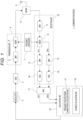
- Fig. 1 is a block diagram illustrating a configuration example of a communication device 1 as a first embodiment according to the present technology.
- the communication device 1 includes a modulator 2, a digital-to-analog converter (DAC) 3, a transmission unit 4, a frequency synthesizer 7, an RF switch (SW) 8, an antenna 9, a reception unit 10, an analog-to-digital converter (ADC) 17, and a calculation unit 18.
- DAC digital-to-analog converter
- SW RF switch
- ADC analog-to-digital converter
- the communication device 1 in the present example can perform wireless communication according to, for example, a Bluetooth Low Energy (BLE: Bluetooth is a registered trademark) system.
- BLE Bluetooth Low Energy
- the modulator 2 performs a signal modulation process for performing wireless communication with another communication device 1.
- the modulation processing for example, IQ modulation is performed.
- each signal of an I channel (In-phase: in-phase component) and a Q channel (Quadrature: quadrature component) is used as a baseband signal.
- the modulator 2 performs modulation processing as IQ modulation on data to be transmitted supplied from the calculation unit 18.
- the DAC 3 converts the digital signal from the modulator 2 into an analog signal.
- the analog signal converted by the DAC 3 is supplied to the transmission unit 4.
- the transmission unit 4 is a block that transmits a signal by wireless communication. As illustrated, the transmission unit 4 includes a band pass filter (BPF) 5 and a mixer 6.
- BPF band pass filter
- the BPF 5 passes only a signal of a specific frequency band. That is, the BPF 5 supplies only a signal of a specific frequency band to the mixer 6 with respect to the analog signal from the DAC 3.
- the mixer 6 mixes a local oscillation frequency supplied from the frequency synthesizer 7 with the signal supplied from the BPF 5 to convert the signal into a transmission frequency of wireless communication.
- the frequency synthesizer 7 supplies a frequency used for transmission and reception.
- the frequency synthesizer 7 includes a local oscillator therein, and is used for conversion of a high-frequency signal and a baseband signal of wireless communication.
- the RF switch 8 is a switch that switches a radio frequency (RF) signal.
- the RF switch 8 connects the transmission unit 4 to the antenna 9 at the time of transmission, and connects the reception unit 10 to the antenna 9 at the time of reception.
- RF radio frequency
- the antenna 9 is an antenna for transmitting and receiving signals by wireless communication.
- the reception unit 10 is a block that receives a signal by wireless communication. As illustrated, the reception unit 10 includes a low noise amplifier (LNA) 11, a mixer 12, a BPF 13, a variable gain amplifier (VGA) 14, a BPF 15, and a VGA 16.
- LNA low noise amplifier
- VGA variable gain amplifier
- the LNA 11 amplifies the RF signal received by the antenna 9.
- the mixer 12 mixes the signal supplied from the LNA 11 with the local oscillation frequency supplied from the frequency synthesizer 7 to convert the signal into each of the I channel signal and the Q channel signal.
- the I channel signal (denoted as “Ich” in the drawing) is supplied to the BPF 13, and the Q channel signal (denoted as "Qch” in the drawing) is supplied to the BPF 15.
- the I channel signal obtained by the mixer 12 is input to the BPF 13, and only a signal in a specific frequency band is extracted and supplied to the VGA 14.
- the Q channel signal obtained by the mixer 12 is input to the BPF 15, and only a signal in a specific frequency band is extracted and supplied to the VGA 16.
- the VGA 14 and the VGA 16 function as analog variable gain amplifiers that adjust gains of the I channel signal supplied from the BPF 13 and the Q channel signal supplied from the BPF 15, respectively.
- the ADC 17 converts the I channel signal and the Q channel signal from the reception unit 10, that is, the I channel signal and the Q channel signal output via the VGA 14 and the VGA 16 from analog signals to digital signals.
- the I channel and Q channel signals converted into the digital signals are supplied to the calculation unit 18.
- the calculation unit 18 includes, for example, a microcomputer including a central processing unit (CPU), a read only memory (ROM), and a random access memory (RAM), and the CPU executes various processes according to, for example, a program stored in the ROM or a program loaded from the ROM to the RAM.
- CPU central processing unit
- ROM read only memory
- RAM random access memory
- the calculation unit 18 performs a process of supplying data to be transmitted to the modulator 2 and modulating the data. Furthermore, the calculation unit 18 also performs a process of demodulating the received data on the basis of the data of the respective signals of the I channel and the Q channel supplied from the ADC 17, or the like.
- the calculation unit 18 in the present example has functions as a frequency-related phase characteristic acquisition unit F1 and a distance calculation unit F2 illustrated in the drawing as functions for performing distance measurement using wireless communication.
- the frequency-related phase characteristic acquisition unit F1 acquires a phase characteristic with respect to a frequency of a signal propagation path with another communication device 1.
- a process of acquiring a phase characteristic with respect to a frequency of a signal propagation path is performed.
- the distance calculation unit F2 calculates the distance to the other communication device 1 on the basis of the phase characteristic with respect to the frequency of the signal propagation path acquired by the frequency-related phase characteristic acquisition unit F1. Note that a method of calculating the distance by the distance calculation unit F2 will also be described later.
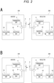
- Fig. 2 is a diagram illustrating a mode example of phase measurement in the phase based method.
- a phase is measured on the basis of a result of performing wireless communication while changing a frequency between two communication devices 1.
- a measurement signal is transmitted from one communication device 1 (referred to as an initiator 100) to the other communication device 1 (referred to as a reflector 200).
- the initiator 100 means the communication device 1 on the side that performs a calculation process of a distance based on the measured phase out of the two communication devices 1, and the reflector 200 means the communication device 1 paired with the initiator 100 that exchanges the measurement signal with the initiator 100.
- Fig. 2 mainly illustrates a flow of a measurement signal related to phase measurement, and for example, the modulator 2, the DAC 3, the frequency synthesizer 7, and the ADC 17 are not illustrated.
- the measurement signal is transmitted from the antenna 9 from the calculation unit 18 via the transmission unit 4. Furthermore, in the reflector 200, the measurement signal is received by the reception unit 10 via the antenna 9.
- a measurement signal is returned from the reflector 200 to the initiator 100. That is, in the reflector 200, the measurement signal is transmitted from the antenna 9 from the calculation unit 18 via the transmission unit 4, and in the initiator 100, the measurement signal is received by the reception unit 10 via the antenna 9, and the phase characteristic between the two is measured in the calculation unit 18.
- the reciprocating communication it is possible to appropriately measure the phase characteristic between the communication devices 1.
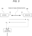
- Fig. 3 is an explanatory diagram of a phase ⁇ of a signal propagation path measured in the phase based method.
- the reflector 200 measures a signal phase ⁇ of the measurement signal.
- the signal phase ⁇ measured when the measurement signal is transmitted from such an initiator 100 side to the reflector 200 side is referred to as " ⁇ IR ".
- the initiator 100 measures the signal phase ⁇ of the measurement signal.
- the signal phase ⁇ measured when the measurement signal is transmitted from the reflector 200 side to the initiator 100 side in this manner is referred to as " ⁇ RI ".
- the signal phase ⁇ is obtained by the following [Expression 1] when the signals of the I channel and the Q channel obtained by receiving the measurement signal are set as "I” and "Q", respectively.
- ⁇ tan ⁇ 1 ⁇ Q / I
- the phase ⁇ of the signal propagation path is obtained on the basis of the signal phase ⁇ IR and the signal phase ⁇ RI described above. Specifically, the phase ⁇ is obtained by averaging the signal phase ⁇ IR and the signal phase ⁇ RI .
- the averaging calculation in addition to the calculation of obtaining the average value of the signal phase ⁇ IR and the signal phase ⁇ RI , calculation as addition of the signal phase ⁇ IR and the signal phase ⁇ RI can also be performed.
- the measurement of the phase ⁇ as described above is performed for each frequency while the frequency of the measurement signal is sequentially changed within a predetermined frequency band.
- the phase ⁇ is measured for each of the plurality of frequencies.
- the predetermined frequency band here, for example, in the case of BLE, it is conceivable to use a frequency band determined as a use band on a communication standard, such as a 2.4 GHz band (band from 2400 MHz to 2480 MHz).
- FIG. 4A A black circle in the drawing indicates a measurement result of the phase ⁇ at each frequency.
- Fig. 4A The result illustrated in Fig. 4A can be rephrased as a phase characteristic with respect to the frequency of the signal propagation path.
- the phase based method distance measurement is performed on the basis of a change mode of the phase ⁇ when the frequency changes. Specifically, in the characteristic of the phase ⁇ with respect to a change in frequency, the magnitude of an inclination of the phase ⁇ as illustrated in Fig. 4B correlates with the magnitude of a distance. At this time, the steeper the inclination of the phase ⁇ , the larger the distance. Therefore, the distance can be calculated on the basis of the inclination of the phase ⁇ .
- the group delay ⁇ is used to eliminate the influence of the 2n indefiniteness of the phase. Note that the group delay ⁇ is obtained by differentiating the phase ⁇ with the angular frequency ⁇ .
- the method of calculating the distance based on the characteristic of the phase ⁇ with respect to the frequency is not limited to the above method, and various methods can be considered.
- it is conceivable to employ a method of acquiring not only the characteristic of the phase ⁇ with respect to the frequency but also the characteristic of the amplitude with respect to the frequency in other words, acquiring not only the frequency characteristic of the phase ⁇ but also the frequency characteristic of the amplitude, converting the frequency characteristic of the phase ⁇ and the amplitude into a time response waveform by inverse Fourier transform such as inverse fast Fourier transform (IFFT), and obtaining the distance on the basis of the time response waveform.
- IFFT inverse fast Fourier transform
- the distance measurement by the phase based method can be performed by measuring the phase ⁇ for at least two or more frequencies.
- the phase based method is a method of calculating the distance by obtaining the phase ⁇ from measurement results of the signal phases ⁇ in both directions from the initiator 100 to the reflector 200 and from the reflector 200 to the initiator 100, and this method, in other words, can be said to be a method of obtaining the distance on the basis of relative difference information of the signal phases ⁇ . Accordingly, the phase based method has an advantage that it is possible to prevent the distance measurement accuracy from deteriorating due to the absolute value of a circuit delay of each block related to signal transmission and reception and a variation value due to the temperature characteristic.
- the phase based method is a method of performing distance measurement on the basis of a change in the phase ⁇ when the frequency changes, if the positional relationship between the communication devices 1 changes during the distance measurement (that is, during the change in the frequency), it becomes difficult to distinguish between the change in the phase ⁇ due to a frequency change and the change in the phase ⁇ due to the position change (distance change), and there is a problem that an error occurs in the distance measurement result.
- Fig. 5 is a diagram illustrating a change characteristic of the phase ⁇ with respect to the frequency in a case where the communication device 1 is displaced.
- the frequency change range for distance measurement is set to the 2.4 GHz band (2400 MHz to 2480 MHz).
- a dotted line indicates characteristics in a case where the communication device 1 is not displaced (there is no change in the distance between the communication devices 1).
- the inclination of the phase ⁇ is different from the original inclination (dotted line).
- the inclination of the phase ⁇ becomes steeper (larger) than the original inclination.
- the inclination of the phase ⁇ becomes gentler (smaller) than the original inclination.
- a distance measurement error caused by displacement of the communication device 1 will be exemplified by specific numerical values.
- Fig. 6 illustrates an example of an actual evaluation result of distance measurement by the phase based method when the communication device 1 moves.
- a horizontal axis represents time (msec)
- a vertical axis represents distance (m)
- Fig. 6 illustrates an evaluation result when the communication device 1 stops at a point of 0.5 m from another communication device 1 for about 6 seconds, then moves at about 1 km/h, and stops at a point of 5 m.
- a solid line represents a distance measurement result
- a dotted line represents a correct value of the distance.
- the distance measurement error is about 20 cm in a stationary region, but the distance measurement error is enlarged according to the start of movement, and an error of about 1 m occurs.
- the magnitude of the distance measurement error changes depending on the relationship between the time of the frequency sweep and the moving speed of the communication device 1 (the change speed of the distance between the communication devices 1). At this time, the distance measurement error tends to increase as the moving speed increases.
- the following distance measurement technique is proposed. That is, in the distance measurement, in acquiring the phase characteristic (the characteristic of the phase ⁇ ) with respect to the frequency of the signal propagation path, the frequency is changed by a frequency change pattern including at least an upward-side change and a downward-side change.
- the frequency-related phase characteristic acquisition unit F1 performs an ascending order characteristic acquisition process of acquiring a phase characteristic by changing the frequency by an ascending order change pattern of changing the frequency in ascending order within a predetermined frequency band, and a descending order characteristic acquisition process of acquiring a phase characteristic by changing the frequency by a descending order change pattern of changing the frequency in descending order within a predetermined frequency band.
- the frequency-related phase characteristic acquisition unit F1 in the present example changes the frequency by one pattern and then changes the frequency by the other pattern with respect to the ascending order change pattern and the descending order change pattern, and acquires the phase characteristic for each pattern.
- the distance calculation unit F2 calculates the distance on the basis of the phase characteristic acquired in the ascending order characteristic acquisition process and the phase characteristic acquired in the descending order characteristic acquisition process.
- the "frequency change pattern” means a pattern of frequency change performed to obtain distance measurement information.
- the frequency change according to the ascending order change pattern and the frequency change according to the descending order change pattern are performed in distance measurement as described above, the ascending order change pattern and the descending order change pattern form one "frequency change pattern".
- Fig. 7 is a diagram for describing the characteristics of the phase ⁇ with respect to frequencies obtained in a case where the frequency is changed in ascending order ( Fig. 7A ) and in a case where the frequency is changed in descending order ( Fig. 7B ).
- the dotted line represents the characteristic of the phase ⁇ in a case where there is no distance change between the communication devices 1
- the solid line represents the characteristic of the phase ⁇ in a case where there is a distance change between the communication devices 1 (in a case where the communication device 1 as the initiator 100 moves away from the communication device 1 as the reflector 200).
- first change control means control on the side where it is performed earlier in terms of time with respect to control for changing a frequency within a predetermined frequency band
- second change control means change control of a frequency performed subsequent to “first change control”.
- the frequency-related phase characteristic acquisition unit F1 first performs any one of the ascending order characteristic acquisition process and the descending order characteristic acquisition process described above to acquire the inclination of the phase ⁇ with respect to any one of the ascending order change and the descending order change, and then performs the other one of the ascending order characteristic acquisition process and the descending order characteristic acquisition process to acquire the inclination of the phase ⁇ with respect to the other one of the ascending order change and the descending order change.
- the distance calculation unit F2 calculates an average value of these two inclinations, and calculates the distance between the communication devices 1 on the basis of the average value.
- a process of acquiring the signal phases ⁇ IR and ⁇ RI is performed for each step of the frequency change.
- the communication device 1 as the initiator 100 performs a process of acquiring the signal phase ⁇ IR measured by the communication device 1 as the reflector 200, and calculates the phase ⁇ based on the acquired signal phase ⁇ IR and the signal phase ⁇ RI measured by the communication device 1 itself.
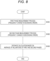
- the processing illustrated in Fig. 8 is executed as software processing by the CPU of the calculation unit 18 illustrated in Fig. 1 .
- step S101 the calculation unit 18 performs either the ascending order characteristic acquisition process or the descending order characteristic acquisition process described above as the first phase measurement process.
- the calculation unit 18 changes the frequency of the measurement signal in ascending order, performs the above-described calculation process of the phase ⁇ for each step of the frequency (including the acquisition process of the signal phase ⁇ IR from the reflector 200) for each frequency, and performs a process of calculating the characteristic of the phase ⁇ with respect to the ascending order change of the frequency, specifically, the inclination of the phase ⁇ .
- the characteristics of the phase ⁇ with respect to the change in frequency are not linear characteristics but characteristics having a variation to some extent. Accordingly, in obtaining the inclination of the phase ⁇ , for example, linear interpolation processing such as a least squares method is performed on the actually obtained phase ⁇ for each frequency.
- step S102 subsequent to step S101 the calculation unit 18 performs the other of the ascending order characteristic acquisition process and the descending order characteristic acquisition process as a second phase measurement process. That is, in the present example, the descending order characteristic acquisition process is performed.
- the content of the descending order characteristic acquisition process here, that is, the process for obtaining the inclination of the phase ⁇ with respect to the descending order change in frequency is similar to the processing content described in step S101 described above except that the frequency of the measurement signal is changed in descending order, and thus redundant description is avoided.
- step S103 the calculation unit 18 performs distance calculation based on an inclination average of first and second phases. That is, an average value of the inclination of the phase ⁇ with respect to the ascending order change obtained in step S101 and the inclination of the phase ⁇ with respect to the descending order change obtained in step S102 is calculated, and the distance between the communication devices 1 is calculated on the basis of the average value.
- the calculation unit 18 terminates the series of processes illustrated in Fig. 8 .
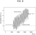
- Fig. 9 is an explanatory diagram of an offset of a distance that occurs in a case where there is a distance change between the communication devices 1.
- the horizontal axis represents time (msec)
- the vertical axis represents distance (m)
- the ascending order characteristic acquisition process and the descending order characteristic acquisition process are alternately performed, and a result of individually calculating the distance from the inclinations of the phase ⁇ obtained in each acquisition process, that is, a result of individually calculating the distance from each inclination without averaging the inclinations of the phase ⁇ obtained in each acquisition process is illustrated.
- the change in the distance between the communication devices 1 is a change in a direction in which the communication device 1 as the initiator 100 moves away from the communication device 1 as the reflector 200 as in the case of Fig. 6 .
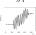
- Fig. 10 illustrates a moving average (dotted line in the drawing) with respect to the distance calculation result illustrated in Fig. 9 .
- the method is a method of averaging the distance calculated on the basis of the characteristic of the phase ⁇ obtained with respect to the ascending order change of the frequency and the distance calculated on the basis of a phase characteristic obtained with respect to the descending order change of the frequency.
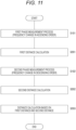
- Fig. 11 is a flowchart illustrating an example of a specific processing procedure for implementing such a distance measurement technique as a modification of the first embodiment.
- the calculation unit 18 first performs the first phase measurement process in step S101. Then, in response to the execution of the first phase measurement process in step S101, the calculation unit 18 in this case executes the first distance calculation process in step S201. Specifically, a process of calculating the distance on the basis of the inclination of the phase ⁇ with respect to the ascending order change obtained in the process of step S101 is performed.
- the calculation unit 18 In response to the execution of the first distance calculation process in step S201, the calculation unit 18 in this case performs the second phase measurement process in step S102 and then performs the second distance calculation process in step S202. That is, a process of calculating the distance on the basis of the inclination of the phase ⁇ with respect to the descending order change obtained in the process of step S102 is performed.
- the calculation unit 18 performs a distance calculation process based on the first distance and the second distance in step S203. Specifically, a process of averaging the distance calculated in step S201 and the distance calculated in step S202 is performed.
- the calculation unit 18 In response to the execution of the process of step S203, the calculation unit 18 terminates the series of processes illustrated in Fig. 11 .
- the distance calculation method in steps S201 and S202 is not limited to the calculation method based on the inclination of the phase ⁇ .
- the distance is calculated by randomly changing the frequency.
- Fig. 12 is a schematic explanatory diagram of a method of randomly changing the frequency, and specifically illustrates the characteristic of the phase ⁇ with respect to the frequency obtained in a case where the frequency of the measurement signal is randomly changed within a predetermined frequency band in a case where the distance between the communication devices 1 changes.
- a white circle represents the value (sample value) of the phase ⁇ obtained with respect to each frequency randomly changed. Furthermore, in Fig. 12 , a dotted line indicates the inclination of the phase ⁇ obtained in a case where the communication device 1 is stationary at a point A, and an alternate long and short dash line indicates the inclination of the phase ⁇ obtained in a case where the communication device 1 is stationary at a point B.
- the value of the phase ⁇ obtained with respect to each frequency is classified into one of these points A and B.
- the samples of the phase ⁇ are dispersed at the point (distance) A and the point (distance) B as illustrated in the drawing. From this, when the inclination of the phase ⁇ is obtained (for example, linear interpolation by a least squares method or the like is performed on the sample) on the basis of the samples for each frequency of the phase ⁇ obtained in a case where the frequency is randomly changed, it can be converged to the inclination indicated by the thick dotted line in the drawing.
- the inclination indicated by the thick dotted line corresponds to the distance between the point A and the point B, and by converging to the inclination indicated by the thick dotted line, the offset with respect to a displacement of the communication device 1 from the point A to the point B is canceled. That is, it is possible to reduce a distance measurement error with respect to a distance change between the communication devices 1.
- the frequency change pattern for randomly changing the frequency as described above belongs to one mode of the frequency change pattern including the upward-side change and the downward-side change of the frequency.
- Fig. 13 is a flowchart illustrating an example of a specific processing procedure for implementing a distance measurement technique corresponding to a case where the frequency is randomly changed.
- a distance measurement technique corresponding to a case where the frequency is randomly changed.
- the calculation unit 18 performs processing of acquiring samples of the phase ⁇ for each frequency by randomly changing the frequency within a predetermined frequency band, and calculating the inclination of the phase ⁇ on the basis of the acquired samples of the phase ⁇ .
- the calculation unit 18 In response to execution of the first phase measurement process in step S301 and the second phase measurement process in step S302, the calculation unit 18 in this case performs distance calculation based on the inclination average of the first and second phases in step S303. That is, processing of calculating the distance on the basis of the average value of the inclinations of the phase ⁇ calculated in each of the first phase measurement process in step S301 and the second phase measurement process in step S302 is performed.
- the number of random changes of the frequency is only required to be at least one, but by employing a method of performing random changes of the frequency a plurality of times as described above and calculating the distance on the basis of the average value of the inclinations of the phase ⁇ obtained with respect to each random change, it is possible to improve the distance measurement accuracy.
- the method described as the modification of the first embodiment can be applied. That is, it is a method in which the random characteristic acquisition process of randomly changing the frequency to acquire the characteristic of the phase ⁇ with respect to the frequency is performed a plurality of times, and the distances calculated from the characteristics of the phase ⁇ acquired in each random characteristic acquisition process are averaged.
- a frequency change pattern is changed on the basis of information of a moving speed of a communication device.
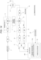
- Fig. 14 is a block diagram illustrating a configuration example of a communication device 1A as a third embodiment.
- a difference from the communication device 1 illustrated in Fig. 1 is that a motion sensor 20 is provided and a calculation unit 18A is provided instead of the calculation unit 18.
- the motion sensor 20 represents a sensor for detecting the motion of the communication device 1A.
- the sensor in this case include an acceleration sensor.
- the moving speed of the communication device 1A can be obtained by time-integrating the output signal of the acceleration sensor.
- a composite sensor including an acceleration sensor represented by an inertial measurement unit (IMU) can be used as the motion sensor 20 for example.
- IMU inertial measurement unit
- the calculation unit 18A is different from the calculation unit 18 in that a frequency-related phase characteristic acquisition unit F1A is included instead of the frequency-related phase characteristic acquisition unit F1.
- the frequency-related phase characteristic acquisition unit F1A changes the frequency change pattern on the basis of the information on the moving speed of the communication device 1A obtained on the basis of the output of the motion sensor.
- the frequency-related phase characteristic acquisition unit F1A changes the frequency by the frequency change pattern including the upward-side change and the downward-side change in a case where the moving speed is equal to or more than a predetermined speed, and changes the frequency by the frequency change pattern including only the upward-side change or only the downward-side change in a case where the moving speed is not equal to or more than the predetermined speed.
- the frequency-related phase characteristic acquisition unit F1A in the present example changes the frequency in one of the ascending order change and the descending order change, and then changes the frequency in the other of the ascending order change and the descending order change, similarly to the first embodiment. That is, one of the ascending order characteristic acquisition process and the descending order characteristic acquisition process is performed, and then the other is performed.
- distance measurement can be performed by an appropriate method according to the presence or absence of a distance change.
- the frequency change is performed by the ascending order change pattern and the descending order change pattern as the frequency change pattern including the upward-side change and the downward-side change
- the frequency change of only one of the ascending order and the descending order needs to be performed as the frequency change in a case where the distance change is not recognized, and thus it is possible to reduce the processing load related to the distance measurement and to shorten the processing time necessary for the distance measurement.
- FIG. 15 illustrates an example of a specific processing procedure for implementing the distance measurement technique as the third embodiment described above.
- the processing illustrated in Fig. 15 is executed as software processing by the CPU of the calculation unit 18A.
- the calculation unit 18A performs the first phase measurement process (in this example, the ascending order characteristic acquisition process with frequency ascending order change) in step S101, and then performs a moving speed acquisition process in step S401. That is, a process of acquiring the moving speed of the communication device 1A is performed by performing predetermined calculation based on the output signal of the motion sensor 20 or the like.
- the calculation unit 18A determines whether or not the moving speed is equal to or higher than a predetermined threshold TH in step S402.
- the calculation unit 18A proceeds to step S403 to perform the distance calculation process based on the inclination of the first phase, that is, the distance calculation process based on the inclination of the phase ⁇ obtained in the acquisition process of step S101, and terminates the series of processing illustrated in Fig. 15 .
- the movement of the communication device 1A is not recognized during the distance measurement, it is possible to perform only one frequency change of the ascending order or the descending order as the frequency change.
- step S402 determines that the moving speed is equal to or more than the threshold TH
- the calculation unit 18A performs the second phase measurement process (in this example, the descending order characteristic acquisition process with a frequency descending order change) in step S102, then performs the distance calculation process in step S103, and terminates the series of processing illustrated in Fig. 15 .
- the second phase measurement process in this example, the descending order characteristic acquisition process with a frequency descending order change
- the distance is calculated on the basis of the characteristics of the phase ⁇ with respect to the frequency changes in both the ascending order and the descending order, and the distance measurement accuracy can be improved.
- the frequency change pattern can be changed according to the moving speed in a similar manner. Specifically, when the moving speed is not equal to or more than the threshold TH, the distance is obtained from the phase characteristic for only the ascending order change pattern, and in a case where the moving speed is equal to or more than the threshold TH, the distance obtained from the phase characteristic for the ascending order change and the distance obtained from the phase characteristic for the descending order change are averaged.
- the third embodiment is also applicable to a case where the frequency is randomly changed as in the second embodiment. Specifically, in this case, it is conceivable to obtain the distance from the phase characteristic only for the ascending or descending order change pattern if the moving speed is not equal to or more than the threshold TH, and to perform the distance calculation based on the characteristic of the phase ⁇ obtained by randomly changing the frequency in a case where the moving speed is equal to or greater than the threshold TH.
- the frequency change pattern for distance measurement is not limited to the patterns exemplified above.
- the frequency is changed by the ascending order change pattern using one frame of an odd number or an even number, and the frequency is changed by the descending order change pattern using the other of the odd or even frames.
- Fig. 16A illustrates an example in which even-numbered frames are allocated to the ascending order change and odd-numbered frames are allocated to the descending order change for the 2.4 GHz band, and in this example, the start frequency of the ascending order change is 2400 MHz, the start frequency of the descending order change is 2480 MHz, and the frequency change amount for each step of the frequency change is 10 MHz in both the ascending order change and the descending order change.
- the frequency change amount for each step of the ascending order change and the descending order change is set to 10 MHz for the convenience of illustration, and of course, the frequency change amount can be set to other than 10 MHz, such as 1 MHz, 2 MHz, or 5 MHz. Furthermore, regarding the ascending order change and the descending order change of the frequency including the ascending order change and the descending order change described in the first embodiment, the frequency change amount for each step can be constant or non-constant.
- the calculation of the distance is only required to be performed on the basis of the characteristic of the phase ⁇ obtained with respect to the ascending order change of the frequency and the characteristic of the phase ⁇ obtained with respect to the descending order change of the frequency.
- the inclination of the phase ⁇ obtained with respect to the ascending order change of the frequency and the inclination of the phase ⁇ obtained with respect to the descending order change of the frequency are obtained, and the distance is calculated on the basis of the average value of the inclinations.
- the frequency change is performed so that the frequency in the ascending order change pattern and the frequency in the descending order change pattern are alternately switched, and the time difference between the ascending order change pattern side and the descending order change pattern side is reduced. That is, under a change in the distance to another communication device, the difference in the distance between the time of setting the frequency in the ascending order change pattern and the time of setting the frequency in the descending order change pattern is suppressed.
- the frequency change pattern may be a change pattern in which advertisement channels (2402 MHz, 2426 MHz, and 2480 MHz) in BLE are excluded.
- the pattern of the frequency change performed temporally earlier can be any one of the ascending order change pattern and the descending order change pattern
- the succeeding frequency change pattern can be the other of the ascending order change pattern and the descending order change pattern.
- the preceding and succeeding frequency change pattern may be a random change pattern.
- both ends may be selected from a low frequency and a high frequency, respectively, thereby securing the inclination.
- the frequency change amount for each step can be made different between both ends and a portion therebetween, such as setting the frequency (2400 MHz to 2404 MHz, 2476 MHz to 2480 MHz) at both ends in increments of 1 MHz, and setting the frequency (from 2404 MHz to 2476 MHz) between both ends in increments of 8 MHz.
- the frequencies at both ends may be partially fixed instead of being selected.
- the frequency change pattern may be a change pattern (non-random pattern) other than the random change pattern.
- wireless communication based on the BLE method is performed as wireless communication for distance measurement
- a specific wireless communication method is not limited, and for example, wireless communication based on another method such as Wi-Fi (registered trademark) or long term evolution (LTE) can be employed.
- Wi-Fi registered trademark
- LTE long term evolution
- a communication device (the same 1 or 1A) as an embodiment includes a phase characteristic acquisition unit (the frequency-related phase characteristic acquisition unit F1 or F1A) that acquires a phase characteristic with respect to a frequency of a signal propagation path with another communication device, and a distance calculation unit (the same F2) that calculates a distance to the another communication device on the basis of the phase characteristic, in which the phase characteristic acquisition unit acquires the phase characteristic by changing the frequency by a frequency change pattern including at least an upward-side change and a downward-side change.
- a phase characteristic acquisition unit the frequency-related phase characteristic acquisition unit F1 or F1A
- F2 the same F2
- phase characteristic obtained by changing the frequency on the upward side and the phase characteristic obtained by changing the frequency on the downward side show a difference corresponding to a distance change with respect to other communication devices, and it is possible to appropriately obtain the distance in a case where there is a distance change by performing distance calculation based on the phase characteristic obtained by changing the frequency by the frequency change pattern including the upward change and the downward change as described above.
- the phase characteristic acquisition unit performs an ascending order characteristic acquisition process of acquiring the phase characteristic by changing the frequency by an ascending order change pattern for changing the frequency in a predetermined frequency band in ascending order and a descending order characteristic acquisition process of acquiring the phase characteristic by changing the frequency by a descending order change pattern for changing the frequency in the predetermined frequency band in descending order
- the distance calculation unit calculates the distance on the basis of the phase characteristic acquired in the ascending order characteristic acquisition process and the phase characteristic acquired in the descending order characteristic acquisition process.
- the inclination of the phase with respect to the frequency is steeper than the inclination in a case where there is no distance change
- the inclination is gentler than the inclination in a case where there is no distance change. Therefore, it is possible to appropriately obtain the distance in a case where there is a distance change by performing distance calculation based on both phase characteristics, such as taking an average of the inclination when changing in ascending order and the inclination when changing in descending order.
- the phase characteristic acquisition unit changes the frequency by one pattern and then changes the frequency by the other pattern with respect to the ascending order change pattern and the descending order change pattern (see Figs. 8 and 15 and the like).
- the frequency change amount at the time of frequency switching can be suppressed.
- the time needed for frequency switching can be shortened, and the processing time needed for distance measurement can be shortened.
- the phase characteristic acquisition unit changes the frequency by the ascending order change pattern using one frame of an odd number or an even number, and changes the frequency by the descending order change pattern using the other frame of the odd number or the even number (see Fig. 16A ).
- the frequency change is performed so that the frequency in the ascending order change pattern and the frequency in the descending order change pattern are alternately switched, and the time difference between the ascending order change pattern side and the descending order change pattern side is reduced. That is, under a change in the distance to another communication device, the difference in the distance between the time of setting the frequency in the ascending order change pattern and the time of setting the frequency in the descending order change pattern is suppressed.
- the distance calculation unit calculates the distance on the basis of an inclination of a phase with respect to a frequency of the signal propagation path obtained with respect to the ascending order change of the frequency and the inclination obtained with respect to the descending order change of the frequency.
- the inclination of the phase with respect to the frequency is steeper than the inclination in a case where there is no distance change
- the inclination is gentler than the inclination in a case where there is no distance change. Therefore, it is possible to appropriately obtain the distance in a case where there is a distance change by performing distance calculation based on both phase characteristics, such as taking an average of the inclination when changing in ascending order and the inclination when changing in descending order.
- the distance calculation unit calculates the distance on the basis of an average value of the inclination obtained with respect to the ascending order change of the frequency and the inclination obtained with respect to the descending order change of the frequency.
- the distance calculation unit averages a distance calculated on the basis of the phase characteristic obtained with respect to the ascending order change of the frequency and a distance calculated on the basis of the phase characteristic obtained with respect to the descending order change of the frequency (see Fig. 11 ).
- the distance to another communication device changes, in a case where the frequency is changed in ascending order, one of positive and negative offsets is superimposed on the distance obtained on the basis of the phase characteristic, and in a case where the frequency is changed in descending order, the other of the positive and negative offsets is superimposed on the distance obtained on the basis of the phase characteristic. Therefore, by averaging the distance when changing in the ascending order and the distance when changing in the descending order, it is possible to appropriately obtain the distance in a case where there is a distance change.
- the phase characteristic acquisition unit performs a random characteristic acquisition process of acquiring the phase characteristic by changing the frequency by a frequency change pattern including a random change of the frequency (see Fig. 13 ).
- the distance to another communication device changes, it is possible to appropriately obtain the distance in a case where there is a distance change by calculating the distance on the basis of the phase characteristic obtained by randomly changing the frequency.
- the distance calculation unit calculates the distance on the basis of each of the phase characteristics acquired by the phase characteristic acquisition unit performing the random characteristic acquisition process a plurality of times.
- the random characteristic acquisition process by performing a plurality of processes to obtain a plurality of phase characteristics, it is possible to improve the accuracy of the distance by performing distance calculation based on the plurality of phase characteristics, such as obtaining the distance by averaging the plurality of phase characteristics.
- the phase characteristic acquisition unit acquires the phase characteristic by changing a frequency by a frequency change pattern in which a part is changed by a random pattern and another part is changed by a non-random pattern (see Figs. 16C and 16D ).
- the phase characteristic acquisition unit performs a process of acquiring an inclination of a phase with respect to a frequency of the signal propagation path as the random characteristic acquisition process, and the distance calculation unit calculates the distance on the basis of an average value of the inclinations acquired by the phase characteristic acquisition unit performing the random characteristic acquisition process a plurality of times.
- the distance calculation unit averages distances calculated from the respective phase characteristics acquired by the phase characteristic acquisition unit performing the random characteristic acquisition process a plurality of times.
- the communication device (the same 1A) as the embodiment includes a motion sensor (the same 20) that detects a motion of the communication device, and the phase characteristic acquisition unit (frequency-related phase characteristic acquisition unit F1A) changes the frequency change pattern on the basis of information of a moving speed of the communication device obtained on the basis of an output of the motion sensor.
- a motion sensor the same 20
- the phase characteristic acquisition unit frequency-related phase characteristic acquisition unit F1A
- the frequency change pattern can be changed according to the presence or absence of a distance change with respect to another communication device.
- the distance measurement can be performed by an appropriate method according to the presence or absence of the distance change, such as performing the distance measurement in which the frequency is changed by the frequency change pattern including the upward-side change and the downward-side change only in a case where the distance change is recognized.
- the phase characteristic acquisition unit changes the frequency by a frequency change pattern including the upward-side change and the downward-side change in a case where the moving speed is equal to or more than a predetermined speed, and changes the frequency by a frequency change pattern including only the upward-side change or only the downward-side change in a case where the moving speed is not equal to or more than the predetermined speed.
- distance measurement can be performed by an appropriate method according to the presence or absence of a distance change.
- a distance measurement method as an embodiment is a distance measurement method in which a communication device includes a phase characteristic acquisition procedure in which a communication device acquires a phase characteristic with respect to a frequency of a signal propagation path with another communication device, and a distance calculation procedure in which the communication device calculates a distance to the another communication device on the basis of the phase characteristic, in which in the phase characteristic acquisition procedure, the phase characteristic is acquired by changing the frequency by a frequency change pattern including at least an upward-side change and a downward-side change.
Landscapes
- Engineering & Computer Science (AREA)
- Radar, Positioning & Navigation (AREA)
- Remote Sensing (AREA)
- Physics & Mathematics (AREA)
- General Physics & Mathematics (AREA)
- Computer Networks & Wireless Communication (AREA)
- Radar Systems Or Details Thereof (AREA)
Applications Claiming Priority (2)
| Application Number | Priority Date | Filing Date | Title |
|---|---|---|---|
| JP2021084747 | 2021-05-19 | ||
| PCT/JP2022/008280 WO2022244369A1 (ja) | 2021-05-19 | 2022-02-28 | 通信装置、測距方法 |
Publications (2)
| Publication Number | Publication Date |
|---|---|
| EP4343377A1 true EP4343377A1 (de) | 2024-03-27 |
| EP4343377A4 EP4343377A4 (de) | 2024-11-13 |
Family
ID=84140926
Family Applications (1)
| Application Number | Title | Priority Date | Filing Date |
|---|---|---|---|
| EP22804290.9A Pending EP4343377A4 (de) | 2021-05-19 | 2022-02-28 | Kommunikationsvorrichtung und entfernungsmessungsverfahren |
Country Status (6)
| Country | Link |
|---|---|
| US (1) | US20240192345A1 (de) |
| EP (1) | EP4343377A4 (de) |
| JP (1) | JPWO2022244369A1 (de) |
| KR (1) | KR20240008839A (de) |
| CN (1) | CN117321451A (de) |
| WO (1) | WO2022244369A1 (de) |
Families Citing this family (2)
| Publication number | Priority date | Publication date | Assignee | Title |
|---|---|---|---|---|
| CN115884080A (zh) * | 2022-11-30 | 2023-03-31 | 深圳开鸿数字产业发展有限公司 | 基于蓝牙的距离测定方法、终端设备及存储介质 |
| WO2024150499A1 (ja) * | 2023-01-13 | 2024-07-18 | アルプスアルパイン株式会社 | 測位システム |
Family Cites Families (14)
| Publication number | Priority date | Publication date | Assignee | Title |
|---|---|---|---|---|
| US6859761B2 (en) * | 2001-01-16 | 2005-02-22 | Bluesoft Ltd. | Accurate distance measurement using RF techniques |
| JP5025675B2 (ja) | 2009-03-19 | 2012-09-12 | 三菱電機株式会社 | 移動体検知システム |
| JP5018943B2 (ja) * | 2010-09-07 | 2012-09-05 | 株式会社デンソー | レーダ装置 |
| JP5620232B2 (ja) * | 2010-11-11 | 2014-11-05 | アルプス電気株式会社 | 距離測定装置 |
| EP2602636A1 (de) * | 2011-12-08 | 2013-06-12 | Nederlandse Organisatie voor toegepast -natuurwetenschappelijk onderzoek TNO | Verfahren zur Bestimmung der Entfernung und der Geschwindigkeit von FMCW-Radarendgeräten |
| US9374113B2 (en) * | 2012-12-21 | 2016-06-21 | Blackberry Limited | Method and apparatus for adjusting the timing of radio antenna tuning |
| US9612325B2 (en) * | 2014-06-02 | 2017-04-04 | Ensco, Inc. | Unwrapping and prediction of distance and velocity measurements using carrier signals |
| JP6877438B2 (ja) * | 2016-01-04 | 2021-05-26 | シメオ ゲゼルシャフト ミット ベシュレンクテル ハフツング | レーダシステムにおける位相ノイズに起因する干渉を低減するための方法及びシステム |
| JP2018048821A (ja) * | 2016-09-20 | 2018-03-29 | 株式会社東海理化電機製作所 | 電波伝搬距離推定装置 |
| EP3316534A1 (de) * | 2016-10-27 | 2018-05-02 | Fraunhofer Gesellschaft zur Förderung der Angewand | Kanalschätzung von frequenzteilbändern |
| JP6829833B2 (ja) | 2017-02-01 | 2021-02-17 | 株式会社東海理化電機製作所 | 電波伝搬距離推定装置 |
| DE102017110404A1 (de) * | 2017-05-12 | 2018-11-15 | Symeo Gmbh | Verfahren und Vorrichtung zur Kompensation von Störeinflüssen |
| JP7250271B2 (ja) * | 2019-02-13 | 2023-04-03 | 株式会社東海理化電機製作所 | 位置検出システム及び位置検出方法 |
| JP2020165696A (ja) * | 2019-03-28 | 2020-10-08 | 三菱重工業株式会社 | 距離推定装置、移動端末、距離推定方法及びプログラム |
-
2022
- 2022-02-28 EP EP22804290.9A patent/EP4343377A4/de active Pending
- 2022-02-28 KR KR1020237037681A patent/KR20240008839A/ko not_active Abandoned
- 2022-02-28 WO PCT/JP2022/008280 patent/WO2022244369A1/ja not_active Ceased
- 2022-02-28 JP JP2023522242A patent/JPWO2022244369A1/ja not_active Abandoned
- 2022-02-28 US US18/555,490 patent/US20240192345A1/en active Pending
- 2022-02-28 CN CN202280034644.5A patent/CN117321451A/zh not_active Withdrawn
Also Published As
| Publication number | Publication date |
|---|---|
| JPWO2022244369A1 (de) | 2022-11-24 |
| EP4343377A4 (de) | 2024-11-13 |
| US20240192345A1 (en) | 2024-06-13 |
| KR20240008839A (ko) | 2024-01-19 |
| CN117321451A (zh) | 2023-12-29 |
| WO2022244369A1 (ja) | 2022-11-24 |
Similar Documents
| Publication | Publication Date | Title |
|---|---|---|
| JP6148622B2 (ja) | レーダ装置 | |
| US8280620B2 (en) | Position calculating method and position calculating device | |
| EP4343377A1 (de) | Kommunikationsvorrichtung und entfernungsmessungsverfahren | |
| US12360225B2 (en) | Communication device and communication method | |
| EP1076244A1 (de) | Fmcw-radar | |
| JP7698630B2 (ja) | 通信装置、通信システム及び通信方法 | |
| JP2005049310A (ja) | 車両用レーダ装置および当該レーダ装置の車両への装着角度調整方法 | |
| JP2009133702A (ja) | 測位装置 | |
| JP2000338230A (ja) | レーダ装置 | |
| JP2006308542A (ja) | 電子走査型ミリ波レーダ装置およびコンピュータプログラム | |
| JP2017146273A (ja) | レーダ装置 | |
| US20240361416A1 (en) | Angle of arrival of wireless local area network devices using a switched beam antenna | |
| US11585939B2 (en) | Base station transmission of GNSS correction data via beacon frame | |
| US20240085550A1 (en) | Communication apparatus, communication system, and communication method | |
| JP2002131423A (ja) | レーダ装置 | |
| JP2009115514A (ja) | 測位方法、プログラム、測位回路及び電子機器 | |
| JP3620459B2 (ja) | レーダ装置 | |
| JPH0836042A (ja) | Gps受信機及びこれに使用する速度決定手段 | |
| US20240393420A1 (en) | Information processing device, information processing method, and program | |
| JP2012194064A (ja) | ホログラフィックレーダ装置 | |
| JP2009097898A (ja) | 測位方法、プログラム、測位装置及び電子機器 | |
| EP4546012A1 (de) | Entfernungsmessvorrichtung | |
| JP3590598B2 (ja) | 距離計測装置及び計測距離処理装置 | |
| US20240340078A1 (en) | Artificial Satellite System and Method for Measuring Distance Between Artificial Satellites | |
| JP2016003870A (ja) | 距離測定装置 |
Legal Events
| Date | Code | Title | Description |
|---|---|---|---|
| STAA | Information on the status of an ep patent application or granted ep patent |
Free format text: STATUS: THE INTERNATIONAL PUBLICATION HAS BEEN MADE |
|
| PUAI | Public reference made under article 153(3) epc to a published international application that has entered the european phase |
Free format text: ORIGINAL CODE: 0009012 |
|
| STAA | Information on the status of an ep patent application or granted ep patent |
Free format text: STATUS: REQUEST FOR EXAMINATION WAS MADE |
|
| 17P | Request for examination filed |
Effective date: 20231206 |
|
| AK | Designated contracting states |
Kind code of ref document: A1 Designated state(s): AL AT BE BG CH CY CZ DE DK EE ES FI FR GB GR HR HU IE IS IT LI LT LU LV MC MK MT NL NO PL PT RO RS SE SI SK SM TR |
|
| DAV | Request for validation of the european patent (deleted) | ||
| DAX | Request for extension of the european patent (deleted) | ||
| A4 | Supplementary search report drawn up and despatched |
Effective date: 20241015 |
|
| RIC1 | Information provided on ipc code assigned before grant |
Ipc: G01S 13/86 20060101ALI20241009BHEP Ipc: G01S 13/84 20060101AFI20241009BHEP |