EP4343748A1 - Dispositif d'affichage et procédé de commande correspondant - Google Patents
Dispositif d'affichage et procédé de commande correspondant Download PDFInfo
- Publication number
- EP4343748A1 EP4343748A1 EP22846075.4A EP22846075A EP4343748A1 EP 4343748 A1 EP4343748 A1 EP 4343748A1 EP 22846075 A EP22846075 A EP 22846075A EP 4343748 A1 EP4343748 A1 EP 4343748A1
- Authority
- EP
- European Patent Office
- Prior art keywords
- led
- blocks
- time period
- current
- control
- Prior art date
- Legal status (The legal status is an assumption and is not a legal conclusion. Google has not performed a legal analysis and makes no representation as to the accuracy of the status listed.)
- Pending
Links
Images








Classifications
-
- G—PHYSICS
- G09—EDUCATION; CRYPTOGRAPHY; DISPLAY; ADVERTISING; SEALS
- G09G—ARRANGEMENTS OR CIRCUITS FOR CONTROL OF INDICATING DEVICES USING STATIC MEANS TO PRESENT VARIABLE INFORMATION
- G09G5/00—Control arrangements or circuits for visual indicators common to cathode-ray tube indicators and other visual indicators
- G09G5/003—Details of a display terminal, the details relating to the control arrangement of the display terminal and to the interfaces thereto
- G09G5/006—Details of the interface to the display terminal
-
- G—PHYSICS
- G09—EDUCATION; CRYPTOGRAPHY; DISPLAY; ADVERTISING; SEALS
- G09G—ARRANGEMENTS OR CIRCUITS FOR CONTROL OF INDICATING DEVICES USING STATIC MEANS TO PRESENT VARIABLE INFORMATION
- G09G3/00—Control arrangements or circuits, of interest only in connection with visual indicators other than cathode-ray tubes
- G09G3/20—Control arrangements or circuits, of interest only in connection with visual indicators other than cathode-ray tubes for presentation of an assembly of a number of characters, e.g. a page, by composing the assembly by combination of individual elements arranged in a matrix no fixed position being assigned to or needed to be assigned to the individual characters or partial characters
- G09G3/22—Control arrangements or circuits, of interest only in connection with visual indicators other than cathode-ray tubes for presentation of an assembly of a number of characters, e.g. a page, by composing the assembly by combination of individual elements arranged in a matrix no fixed position being assigned to or needed to be assigned to the individual characters or partial characters using controlled light sources
- G09G3/30—Control arrangements or circuits, of interest only in connection with visual indicators other than cathode-ray tubes for presentation of an assembly of a number of characters, e.g. a page, by composing the assembly by combination of individual elements arranged in a matrix no fixed position being assigned to or needed to be assigned to the individual characters or partial characters using controlled light sources using electroluminescent panels
- G09G3/32—Control arrangements or circuits, of interest only in connection with visual indicators other than cathode-ray tubes for presentation of an assembly of a number of characters, e.g. a page, by composing the assembly by combination of individual elements arranged in a matrix no fixed position being assigned to or needed to be assigned to the individual characters or partial characters using controlled light sources using electroluminescent panels semiconductive, e.g. using light-emitting diodes [LED]
-
- H—ELECTRICITY
- H05—ELECTRIC TECHNIQUES NOT OTHERWISE PROVIDED FOR
- H05B—ELECTRIC HEATING; ELECTRIC LIGHT SOURCES NOT OTHERWISE PROVIDED FOR; CIRCUIT ARRANGEMENTS FOR ELECTRIC LIGHT SOURCES, IN GENERAL
- H05B45/00—Circuit arrangements for operating light-emitting diodes [LED]
- H05B45/10—Controlling the intensity of the light
-
- H—ELECTRICITY
- H05—ELECTRIC TECHNIQUES NOT OTHERWISE PROVIDED FOR
- H05B—ELECTRIC HEATING; ELECTRIC LIGHT SOURCES NOT OTHERWISE PROVIDED FOR; CIRCUIT ARRANGEMENTS FOR ELECTRIC LIGHT SOURCES, IN GENERAL
- H05B45/00—Circuit arrangements for operating light-emitting diodes [LED]
- H05B45/30—Driver circuits
- H05B45/32—Pulse-control circuits
- H05B45/325—Pulse-width modulation [PWM]
-
- H—ELECTRICITY
- H05—ELECTRIC TECHNIQUES NOT OTHERWISE PROVIDED FOR
- H05B—ELECTRIC HEATING; ELECTRIC LIGHT SOURCES NOT OTHERWISE PROVIDED FOR; CIRCUIT ARRANGEMENTS FOR ELECTRIC LIGHT SOURCES, IN GENERAL
- H05B45/00—Circuit arrangements for operating light-emitting diodes [LED]
- H05B45/30—Driver circuits
- H05B45/32—Pulse-control circuits
- H05B45/33—Pulse-amplitude modulation [PAM]
-
- H—ELECTRICITY
- H05—ELECTRIC TECHNIQUES NOT OTHERWISE PROVIDED FOR
- H05B—ELECTRIC HEATING; ELECTRIC LIGHT SOURCES NOT OTHERWISE PROVIDED FOR; CIRCUIT ARRANGEMENTS FOR ELECTRIC LIGHT SOURCES, IN GENERAL
- H05B45/00—Circuit arrangements for operating light-emitting diodes [LED]
- H05B45/40—Details of LED load circuits
- H05B45/44—Details of LED load circuits with an active control inside an LED matrix
-
- H—ELECTRICITY
- H05—ELECTRIC TECHNIQUES NOT OTHERWISE PROVIDED FOR
- H05B—ELECTRIC HEATING; ELECTRIC LIGHT SOURCES NOT OTHERWISE PROVIDED FOR; CIRCUIT ARRANGEMENTS FOR ELECTRIC LIGHT SOURCES, IN GENERAL
- H05B47/00—Circuit arrangements for operating light sources in general, i.e. where the type of light source is not relevant
- H05B47/10—Controlling the light source
- H05B47/16—Controlling the light source by timing means
-
- H—ELECTRICITY
- H05—ELECTRIC TECHNIQUES NOT OTHERWISE PROVIDED FOR
- H05B—ELECTRIC HEATING; ELECTRIC LIGHT SOURCES NOT OTHERWISE PROVIDED FOR; CIRCUIT ARRANGEMENTS FOR ELECTRIC LIGHT SOURCES, IN GENERAL
- H05B47/00—Circuit arrangements for operating light sources in general, i.e. where the type of light source is not relevant
- H05B47/10—Controlling the light source
- H05B47/165—Controlling the light source following a pre-assigned programmed sequence; Logic control [LC]
-
- G—PHYSICS
- G09—EDUCATION; CRYPTOGRAPHY; DISPLAY; ADVERTISING; SEALS
- G09G—ARRANGEMENTS OR CIRCUITS FOR CONTROL OF INDICATING DEVICES USING STATIC MEANS TO PRESENT VARIABLE INFORMATION
- G09G2310/00—Command of the display device
- G09G2310/04—Partial updating of the display screen
-
- G—PHYSICS
- G09—EDUCATION; CRYPTOGRAPHY; DISPLAY; ADVERTISING; SEALS
- G09G—ARRANGEMENTS OR CIRCUITS FOR CONTROL OF INDICATING DEVICES USING STATIC MEANS TO PRESENT VARIABLE INFORMATION
- G09G2310/00—Command of the display device
- G09G2310/08—Details of timing specific for flat panels, other than clock recovery
-
- G—PHYSICS
- G09—EDUCATION; CRYPTOGRAPHY; DISPLAY; ADVERTISING; SEALS
- G09G—ARRANGEMENTS OR CIRCUITS FOR CONTROL OF INDICATING DEVICES USING STATIC MEANS TO PRESENT VARIABLE INFORMATION
- G09G2320/00—Control of display operating conditions
- G09G2320/06—Adjustment of display parameters
- G09G2320/0626—Adjustment of display parameters for control of overall brightness
-
- G—PHYSICS
- G09—EDUCATION; CRYPTOGRAPHY; DISPLAY; ADVERTISING; SEALS
- G09G—ARRANGEMENTS OR CIRCUITS FOR CONTROL OF INDICATING DEVICES USING STATIC MEANS TO PRESENT VARIABLE INFORMATION
- G09G2320/00—Control of display operating conditions
- G09G2320/06—Adjustment of display parameters
- G09G2320/0626—Adjustment of display parameters for control of overall brightness
- G09G2320/0633—Adjustment of display parameters for control of overall brightness by amplitude modulation of the brightness of the illumination source
-
- G—PHYSICS
- G09—EDUCATION; CRYPTOGRAPHY; DISPLAY; ADVERTISING; SEALS
- G09G—ARRANGEMENTS OR CIRCUITS FOR CONTROL OF INDICATING DEVICES USING STATIC MEANS TO PRESENT VARIABLE INFORMATION
- G09G2330/00—Aspects of power supply; Aspects of display protection and defect management
- G09G2330/02—Details of power systems and of start or stop of display operation
- G09G2330/021—Power management, e.g. power saving
-
- G—PHYSICS
- G09—EDUCATION; CRYPTOGRAPHY; DISPLAY; ADVERTISING; SEALS
- G09G—ARRANGEMENTS OR CIRCUITS FOR CONTROL OF INDICATING DEVICES USING STATIC MEANS TO PRESENT VARIABLE INFORMATION
- G09G2370/00—Aspects of data communication
- G09G2370/16—Use of wireless transmission of display information
-
- H—ELECTRICITY
- H05—ELECTRIC TECHNIQUES NOT OTHERWISE PROVIDED FOR
- H05B—ELECTRIC HEATING; ELECTRIC LIGHT SOURCES NOT OTHERWISE PROVIDED FOR; CIRCUIT ARRANGEMENTS FOR ELECTRIC LIGHT SOURCES, IN GENERAL
- H05B45/00—Circuit arrangements for operating light-emitting diodes [LED]
- H05B45/40—Details of LED load circuits
- H05B45/44—Details of LED load circuits with an active control inside an LED matrix
- H05B45/48—Details of LED load circuits with an active control inside an LED matrix having LEDs organised in strings and incorporating parallel shunting devices
Definitions
- the disclosure relates to a display device, and more specifically, to a display device including light emitting diodes.
- display devices are a type of output devices for visually displaying obtained or stored image information to a user, and are used in various fields such as home or workplace.
- the display devices include, for example, a monitor device connected to a personal computer or a server computer, a portable computer device, a navigation terminal device, a general television device, Internet Protocol Television (IPTV), portable terminal devices such as a smartphone, tablet Personal Computer (PC), a Personal Digital Assistant (PDA) or a cellular phone, various display devices used to reproduce images such as advertisements or movies in an industrial field, or various kinds of audio/video systems.
- a monitor device connected to a personal computer or a server computer
- a portable computer device a navigation terminal device
- a general television device Internet Protocol Television (IPTV)
- portable terminal devices such as a smartphone, tablet Personal Computer (PC), a Personal Digital Assistant (PDA) or a cellular phone
- various display devices used to reproduce images such as advertisements or movies in an industrial field, or various kinds of audio/video systems.
- the display devices may display an image using various types of display panels.
- the display devices may include a cathode ray tube panel, a Light Emitting Diode (LED) panel, an Organic LED (OLED) panel, a Liquid Crystal Display (LCD) panel, and the like.
- LED Light Emitting Diode
- OLED Organic LED
- LCD Liquid Crystal Display
- LED as a light source in a display device
- LED may be used in a backlight unit of an LCD device or as individual pixels in an LED panel.
- the disclosure is directed to providing a display device that may control a Light Emitting Diode (LED) in a time division manner to implement high resolution while minimizing an increase in the number of driver Integrated Circuits (ICs) required to drive the LED, and a method for controlling the same.
- LED Light Emitting Diode
- One aspect of the disclosure provides a display device including: a plurality of Light Emitting Diode (LED) blocks (groups) configured to be connected in series to each other; a driver Integrated Circuit (IC) configured to supply a current to the plurality of LED blocks, and be connected in series to one LED block of the plurality of LED blocks; a plurality of switching elements configured to be connected in parallel to each of the plurality of LED blocks; and a controller configured to control on/off of the plurality of switching elements to adjust an LED block to which the current is supplied from among the plurality of LED blocks, over a time for implementing a unit frame.
- LED Light Emitting Diode
- IC Integrated Circuit
- the controller may be configured to divide the time for implementing the unit frame into a plurality of time periods, control on/off of the plurality of switching elements to supply the current to a portion of the plurality of LED blocks in a portion of the plurality of time periods, and control on/off of the plurality of switching elements to supply the current to all of the plurality of LED blocks in another portion of the plurality of time periods.
- the display device may further include a power supply configured to be connected in series to another LED block from among the plurality of LED blocks to supply a drive voltage (VDD), and the controller may be configured to control the power supply to adjust the drive voltage supplied to the plurality of LED blocks over the time for implementing the unit frame.
- VDD drive voltage
- the controller may be configured to control the power supply to increase or decrease the drive voltage supplied to the LED block in response to an increase or a decrease in a number of LED blocks to which the current is supplied from among the plurality of LED blocks according to on/off of the switching element.
- the controller may be configured to control the power supply to increase the drive voltage in response to the increase in the number of LED blocks to which the current is supplied, and control the power supply to decrease the drive voltage in response to the decrease in the number of LED blocks to which the current is supplied.
- the plurality of LED blocks may include a first LED block; and a second LED block configured to be connected in series to the first LED block, and the plurality of switching elements may include a first switching element configured to be connected in parallel to the first LED block; and a second switching element configured to be connected in parallel to the second LED block.
- the time for implementing the unit frame may include a first time period, a second time period, and a third time period
- the first time period may indicate a time period corresponding to a first half of the time for implementing the unit frame
- the second time period may indicate a time period corresponding to a first half of a remaining half of the time for implementing the unit frame
- the third time period may indicate a time period corresponding to a last quarter of the time for implementing the unit frame
- the controller may be configured to control both the first switching element and the second switching element to be turned off for the first time period.
- the controller may be configured to control the first switching element to be turned off and control the second switching element to be turned on for the second time period, and control the first switching element to be turned on and control the second switching element to be turned off for the third time period.
- the controller may be configured to control the power supply to supply a voltage equivalent to twice a drive voltage required for an operation of a single LED block for the first time period, and supply a drive voltage required for an operation of a single LED block for the second time period and the third time period.
- the controller may be configured to control the driver IC to output the current according to data to be emitted from each of the LED blocks.
- the controller may be configured to control the plurality of LED blocks to represent a luminance using one of a Pulse Width Modulation (PWM) control or a Pulse Amplitude Modulation (PAM) control.
- PWM Pulse Width Modulation
- PAM Pulse Amplitude Modulation
- One aspect of the disclosure provides a method for controlling a display device including a plurality of Light Emitting Diode (LED) blocks configured to be connected in series to each other, a driver Integrated Circuit (IC) configured to supply a current to the plurality of LED blocks and be connected in series to one LED block of the plurality of LED blocks, and a plurality of switching elements configured to be connected in parallel to each of the plurality of LED blocks, the method including: determining an LED block to which the current is supplied from among the plurality of LED blocks, over a time for implementing a unit frame; and controlling on/off of the plurality of switching elements to supply the current to the determined LED block.
- LED Light Emitting Diode
- IC Driver Integrated Circuit
- the controlling of on/off of the plurality of switching elements may further include dividing the time for implementing the unit frame into a plurality of time periods, controlling on/off of the plurality of switching elements to supply the current to a portion of the plurality of LED blocks in a portion of the plurality of time periods, and controlling on/off of the plurality of switching elements to supply the current to all of the plurality of LED blocks in another portion of the plurality of time periods.
- the method may further include adjusting a drive voltage supplied to the plurality of LED blocks over the time for implementing the unit frame.
- the adjusting of the drive voltage may include increasing or decreasing the drive voltage supplied to the LED block in response to an increase or a decrease in a number of LED blocks to which the current is supplied from among the plurality of LED blocks according to on/off of the switching element.
- a circuit may be simplified and cost may be reduced by reducing the number of required driver Integrated Circuits (ICs) while implementing a high resolution.
- ICs Integrated Circuits
- power consumption and heat generation may be reduced by adjusting power supplied from a power supply in response to the number of LED blocks that are driven.
- FIG. 1 is a diagram of an exterior of a display device according to an embodiment.
- FIG. 2 is an exploded perspective view of partial configuration of a display device according to an embodiment.
- a display device 100 is a device capable of processing an image signal received from the outside and visually displaying a processed image.
- the display device 100 is a television (TV) is exemplified, but is not limited thereto.
- the display device 100 may be implemented in various forms, such as a monitor, a portable multimedia device, a portable communication device, a portable computing device, and the like, and the form of the display device 100 is not limited as long as it is a device that visually displays an image.
- the display device 100 may be a Large Format Display (LFD) installed outdoors, such as on a roof of a building or at a bus stop.
- LFD Large Format Display
- the outdoors is not necessarily limited to the outdoors, and the display device 100 may be installed wherever a large number of people may enter and exit, even indoors such as at subway stations, shopping malls, movie theaters, office buildings, and stores.
- the display device 100 may receive a video signal and an audio signal from various content sources, and output video and audio corresponding to the video signal and the audio signal, respectively.
- the display device 100 may receive television broadcast content through a broadcast reception antenna or a wired cable, receive content from a content playback apparatus, or receive content from a content-providing server of a content provider.
- the display device 100 may include a self-luminous display panel displaying an image using an element emitting light by itself.
- the self-luminous display panel may include a Light Emitting Diode (LED) panel.
- the self-luminous display panel may also include a non-self-luminous display panel that transmits or blocks light emitted from a backlight unit to display an image.
- the non-self-luminous display panel may include a Liquid Crystal Display (LCD) panel, and the like.
- the display device 100 may include a body 101 including a plurality of components for displaying an image, and a screen S provided on one side of the body 101 to display an image I.
- the body 101 forms an exterior of the display device 100, and components of the display device 100 for displaying the image I may be provided inside the body 101. It is illustrated in FIG. 1 that the body 101 has a flat plate shape, but the shape of the body 101 is not limited to that shown in FIG. 1 .
- the body 101 may have a curved shape such that both left and right ends protrude forward and a center is concave.
- the screen S is formed on a front surface of the body 101, and the image I, which is visual information, may be displayed on the screen S.
- the screen S may display a still image or a video, as well as a two-dimensional (2D) plane image or a three-dimensional (3D) stereoscopic image.
- the display device 100 may be implemented as a stand type, as shown in FIG. 1 , or may be implemented as a wall-mounted type.
- the display device 100 may be implemented in a rectangular shape where a width (a length in an Y-axis direction) is shorter than a height (a length in a Z-axis direction), may be implemented in a rectangular shape where the width is longer than the height, or may be implemented in a square shape.
- a method of supporting the display device 100 or a shape of the display device 100 is not limited.
- a direction (+X direction) in which an image is output is defined as a forward direction
- an opposite direction (-X direction) is defined as a rear direction.
- an XYZ axis coordinate system is based on the display device 100, and even in a case where the display device 100 is not upright as shown in FIG. 1 and is laid down, the coordinate system based on the display device 100 is not changed.
- FIG. 2 is a control block diagram of a display device according to an embodiment.
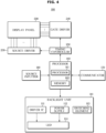
- the display device 100 may include an LED 114, a driver Integrated Circuit (IC) 111 driving the LED 114, a power supply 112 supplying a drive voltage to the LED 114, a switching element 113 adjusting an LED to which current is supplied, and a controller 160 controlling the switching element 113.
- IC Integrated Circuit
- the display device 100 may include a plurality of LEDs 114 as a light source for displaying an image.
- the plurality of LEDs 114 may be arranged in one-dimensional or two-dimensional matrix.
- the driver IC 111 may supply current to the LED 114 to represent a luminance corresponding to image data.
- the plurality of LEDs 114 may be divided into a plurality of LED groups, and each of the LED groups may include a plurality of LEDs 114 connected to each other in series.
- the switching element 113 may be connected in parallel to each of the LED groups.
- N LED groups (N is an integer equal to or greater than 2) are connected in series is described.
- a single driver IC 111 may control the N LED groups.
- the driver IC 111 may be connected in series to a single LED block from among the plurality of LED blocks to supply current to the LED block.
- the driver IC 111 may be connected to one of two LED blocks disposed at both ends, from among the plurality of LED blocks connected in series.
- the power supply 112 may be connected in series to another LED block from among the plurality of LEDs 114 to supply a drive voltage (VDD) required to drive the LED 114.
- VDD drive voltage
- the power supply 112 may be connected to the other one of the two LED blocks disposed at both ends.
- Vb a drive voltage required to drive a single LED block
- the switching element 113 may be connected in parallel to each of the plurality of LED blocks, and an LED block that emit light may vary depending on whether the switching element 113 is turned on or off.
- the controller 160 may control the switching element 113 to adjust an LED block to which current is supplied from among the plurality of LED blocks.
- the controller 160 may implement high resolution without increasing the number of driver ICs, which is described in detail later.
- the LED 114 may be used as a light source of a backlight unit, or may be inserted into a self-luminous display panel and used as a respective pixel.
- a light source of the backlight unit 110 is described.
- the LED 114 is used as a light source of the backlight unit 110
- a display device including the backlight unit 110 is described first.
- FIG. 3 is an exploded perspective view of a partial configuration of a display device according to an embodiment.
- FIG. 4 is a control block diagram of a display device according to an embodiment.
- the backlight unit 110 emitting surface light forward, and a liquid crystal panel 130 blocking or transmitting the light emitted from the backlight unit 110 according to an image signal to be output may be provided.
- the body 103 is provided with the liquid crystal panel 130, a bezel 101a for supporting and fixing the backlight unit 110, a frame middle mold 101b, a bottom chassis 101c, and a back cover 101d.
- the backlight unit 110 is installed behind the liquid crystal panel and supplies light required for the liquid crystal panel to display an image.
- the backlight unit may be divided into an edge-type backlight unit in which a light source is disposed on a side of the liquid crystal panel, and a direct-type backlight unit in which a light source is disposed two-dimensionally on a lower portion of the liquid crystal panel.
- the backlight unit 110 may include a plurality of point light sources that emit monochromatic light such as blue light, or white light, and may refract, reflect, and scatter light to convert the light emitted from the point light sources into uniform surface light.
- monochromatic light such as blue light, or white light
- the liquid crystal panel 130 is provided in front of the backlight unit 110 and may form an image by blocking or transmitting the light emitted from the backlight unit 110.
- the liquid crystal panel 130 may include a plurality of pixels arranged in a two-dimensional matrix form.
- the plurality of pixels included in the liquid crystal panel 130 may independently block or transmit the light emitted from the backlight unit 110, and an image may be displayed on the screen 105 by the light emitted from the plurality of pixels.
- the backlight unit 111 requires to control and drive the LED 114, inserted as a light source of the backlight unit 111, so as to supply light required for the liquid crystal panel to display an image.
- a process of controlling the LED 114 is described.
- the controller 160 may control the driver IC 111 and the power supply 112, included in the backlight unit 110, to supply current and drive voltage to the LED 114. In addition, by controlling on/off of the switching element 113, the controller 160 may adjust the LED 114 to which the current and the drive voltage are supplied.
- a timing controller 250 may convert an image signal transmitted from the main controller into an image signal in a form that may be processed by a panel driver, and generate a control signal used to display the image signal on the display device.
- the panel driver drives a panel of the liquid crystal display, and may include a gate driver 240 providing a gate signal to a gate line and a source driver 230 providing a data signal to a data line.
- a gate driver 240 providing a gate signal to a gate line
- a source driver 230 providing a data signal to a data line.
- the gate driver 240 and the source driver 230 may be implemented as a Display Driver Integrated circuit (DDI).
- DPI Display Driver Integrated circuit
- the source driver 230 may convert image data into an analog voltage and supply to the gate line, and the gate driver 240 may supply an analog voltage pulse waveform to the gate line according to a control signal.
- the controller 160 may control the source driver 230 and the gate driver 240 to supply the image data to the gate line.
- the display device may further include a communicator 170 for performing wireless communication with an external electronic device.
- the communicator 170 may include at least one communication module transmitting and receiving data according to a predetermined communication protocol.
- the communicator 170 may include at least one of a variety of wireless communication modules that may be connected to the Internet through wireless communication methods such as, Wi-Fi, Wireless Broadband (Wibro), Global System for Mobile Communication (GSM), Code Division Multiple Access (CDMA), Wideband Code Division Multiple Access (WCDMA), Universal Mobile Telecommunications System (UMTS), Time Division Multiple Access (TDMA), Long Term Evolution (LTE), 4 th generation (4G) mobile communications, 5 th generation (5G) mobile communications, and the like.
- Wi-Fi Wireless Broadband
- GSM Global System for Mobile Communication
- CDMA Code Division Multiple Access
- WCDMA Wideband Code Division Multiple Access
- UMTS Universal Mobile Telecommunications System
- TDMA Time Division Multiple Access
- LTE Long Term Evolution
- 4G 4 th generation
- 5G 5
- the communicator 170 may perform operations such as communicating with a central server that controls the display device 100, receiving information required by a user from an external server, or transmitting information input by the user to an external server.
- a source inputter 180 may receive a source signal input from a settop box, Universal Serial Bus (USB), antenna, and the like. Accordingly, the source inputter 180 may include at least one selected from a group of source input interfaces including a High Definition Multimedia Interface (HDMI) cable port, USB port, antenna, and the like.
- HDMI High Definition Multimedia Interface
- FIG. 5 is a diagram illustrating a structure including a plurality of LED blocks according to an embodiment.
- a single LED block may include a plurality of LEDs 114 connected in series to each other.
- Each of the LED blocks may be connected in series to each other, and the driver IC 111 connected in series to a single LED block from among the plurality of LED blocks may supply current I to the plurality of LED blocks.
- each of the plurality of switching elements 113 may be connected in parallel to each of the plurality of LED blocks.
- the controller 160 may control on/off of the plurality of switching elements 113 to adjust an LED block to which the current I is supplied from among the plurality of LED blocks, over time for implementing a unit frame.
- the current I flows to an LED block connected in parallel to the corresponding switching element 113, and in response to the switching element 113 being turned on, the current I flows to the switching element 113, not the LED block connected in parallel to the corresponding switching element 113.
- the controller 160 may divide the time for implementing the unit frame into a plurality of time periods, may control on/off of the plurality of switching elements to supply current to a portion of the plurality of LED blocks in a portion of the plurality of time periods, and may control on/off of the plurality of switching elements to supply current to all of the plurality of LED blocks in another portion of the plurality of time periods.
- LED blocks driven for each time period may vary.
- the power supply 112 is a device that may supply a drive voltage Vb to the plurality of LED blocks Block, and may be connected in series to another LED block from among the plurality of LED blocks Block.
- the controller 160 may control the power supply to adjust the drive voltage supplied to the plurality of LED blocks over a time for implementing the unit frame.
- the controller 160 may control the plurality of LED blocks to which the current is supplied according to on/off of the switching element 113, and in response to an increase or decrease in the number of LED blocks to which the current is supplied, the controller 160 may control the power supply 112 to increase or decrease the drive voltage supplied to the LED block.
- the controller 160 may control the power supply to increase the drive voltage in response to an increase in the number of LED blocks to which the current is supplied, and may control the power supply to decrease the drive voltage in response to a decrease in the number of LED blocks to which the current is supplied.
- the power supply 112 may supply a voltage equivalent to n * Vb. In response to the number of LED blocks through which current flows being increased to m (m > n) by controlling the switching element 113, the power supply 112 may supply the increased voltage equivalent to m * Vb.
- FIG. 6 is a diagram illustrating a structure including two LED blocks according to an embodiment.
- FIG. 7 is a diagram illustrating controlling on/off of a switch by dividing a unit frame into a plurality of time periods according to an embodiment.
- a first LED block Block 1 and a second LED block Block 2 are connected to each other in series, and a first switching element SW 1 and a second switching element SW 2 are connected in parallel to the first LED block Block 1 and the second LED block Block 2, respectively.
- the driver IC 111 is connected in series to the second LED block Block 2, and the power supply 15 is connected in series to the first LED block Block 1.
- the controller 160 may divide a time for implementing a unit frame into a plurality of time periods and control to perform a different operation for each time period.
- the controller 160 may divide the time for implementing the unit frame into a first time period, a second time period, and a third time period.
- the first time period may indicate a time period corresponding to a first half of the time for implementing the unit frame
- the second time period may indicate a time period corresponding to a first half of a remaining half of the time for implementing the unit frame
- the third time period may indicate a time period corresponding to a last quarter of the time for implementing the unit frame.
- time periods described above is an example, and the time periods may be divided in different manners.
- the controller 160 may control both the first switching element SW 1 and the second switching element SW2 to be turned off for the first time period.
- current I may be supplied to both the first LED block Block1 and the second LED block Block2.
- the controller 160 may control the first switching element SW1 to be turned off and control the second switching element SW2 to be turned on for the second time period.
- the current I may flow only to the first LED block Block1, not to the second LED block Block2.
- the controller 160 may control the first switching element SW1 to be turned on and control the second switching element SW2 to be turned off for the third time period. In this case, the current I may flow only to the second LED block Block2, not to the first LED block Block1.
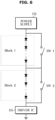
- FIG. 8 is a diagram illustrating an example where two switching elements are turned off according to an embodiment.
- FIG. 9 is a diagram illustrating an example where a first switching element is turned off and a second switching element is turned on according to an embodiment.
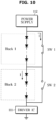
- FIG. 10 is a diagram illustrating an example where a first switching element is turned on and a second switching element is turned off according to an embodiment.
- FIG. 8 a circuit diagram where the controller 160 controls both a first switching element SW1 and a second switching element SW2 to be turned off in the first time period is illustrated.
- the current I is supplied to both the first LED block Block1 and the second LED block Block2, and thus a plurality of LEDs included in each of the LED blocks emit light. Accordingly, all of the first LED block Block1 and the second LED block Block2 emit light.
- FIG. 9 a circuit diagram where the controller 160 controls a first switching element SW1 to be turned off and controls a second switching element SW2 to be turned on in the second time period is illustrated.
- the first switching element SW1 is turned off and a conductive line is not connected, current I supplied from the driver IC 111 may be supplied to a first LED block Block1.
- the second switching element SW2 is turned on and a conductive line is connected, the current I supplied from the driver IC 111 may not be supplied to a second LED block Block2 and may flow only to the second switching element SW2.
- the current I is supplied to the first LED block Block1 and a plurality of LEDs included in the first LED block emit light, and thus the first LED block Block1 emits light.
- the second LED block Block2 does not emit light because the second LED block Block2 is not supplied with the current I.
- FIG. 10 a circuit diagram where the controller 160 controls a first switching element SW1 to be turned on and controls a second switching element SW2 to be turned off in the third time period is illustrated.
- the second switching element SW2 is turned off and a conductive line is not connected, current I supplied from the driver IC 111 may be supplied to a second LED block Block1. However, because the first switching element SW1 is turned on and the conductive line is connected, the current I supplied from the driver IC 111 may not be supplied to a first LED block Block1 and may flow only to the first switching element SW1.
- the current I is supplied to the second LED block Block2 and a plurality of LEDs included in the second LED block emit light, and thus the second LED block Block1 emits light.
- the first LED block Block2 which is not supplied with the current I does not emit light.
- FIG. 11 is a diagram illustrating a time at which an LED block emits light according to on/off of a switching element for each time period according to an embodiment.
- both the first switching element SW1 and the second switching element SW2 are controlled to be turned off, and thus both the first LED block Block1 and the second LED block Block2 may be supplied with current and emit light.
- the first switching element SW1 is controlled to be turned off and the second switching element SW2 is controlled to be turned on, and thus only the first LED block Block1 may be supplied with current and emit light.
- the first switching element SW1 is controlled to be turned on and the second switching element SW2 is controlled to be turned off, and thus only the second LED block Block2 may be supplied with current and emit light.
- the controller 160 may divide a time for implementing a unit frame into a plurality of time periods, control on/off of the switching element 113 for each time period, and adjust an LED block that is supplied with current and emits light.
- the controller 160 may control the power supply 112 to vary a drive voltage supplied by the power supply 112 according to the number of driving LED blocks in order to reduce power consumption and heat generation.
- FIG. 12 is a diagram illustrating supplying a drive voltage by a power supply in response to two LED blocks emitting light according to an embodiment.
- FIG. 13 is a diagram illustrating supplying a drive voltage by a power supply in response to only one of two LED blocks emitting light according to an embodiment.
- FIG. 12 a circuit diagram where the controller 160 controls both a first switching element SW1 and a second switching element SW2 to be turned off in the first time period is illustrated.
- the power supply may supply a drive voltage corresponding to the number of LED blocks that emit light.
- the power supply 112 may supply a voltage 2Vb that is twice a drive voltage Vb required to drive a single LED block.
- FIG. 13 a circuit diagram ((a) in FIG. 13 ) where the controller 160 controls a first switching element SW1 to be turned off and controls a second switching element SW2 to be turned on in the second time period, and a circuit diagram ((b) of FIG. 13 ) where the controller 160 controls the first switching element SW1 to be turned on and controls the second switching element SW2 to be turned off in the third time period are illustrated.
- only the first LED block may be supplied with current and emit light in the second time period, and only the second LED block may be supplied with current and emit light in the third time period.
- the power supply 112 may supply a voltage equivalent to the drive voltage Vb required to drive a single LED block.
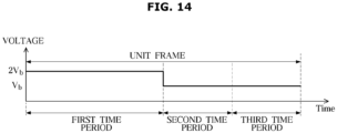
- FIG. 14 is a diagram illustrating a supply voltage supplied by a power supply for each time period according to an embodiment.
- the power supply 112 may supply a voltage twice as much as a drive voltage Vb required to drive a single LED block.
- the power supply 112 may supply a voltage equivalent to the drive voltage Vb required to drive a single LED block.
- power consumption and heat generation may be reduced by supplying only as much drive voltage as the number of LED blocks which are emitting light.
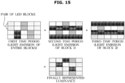
- FIG. 15 is a diagram illustrating a luminance representation method of a display device according to an embodiment.
- each block represents an LED block.
- FIG. 15 shows a structure in which two LED blocks located above and below form a pair and a total of 10 pairs of LED blocks are combined.
- the two LED blocks above and below may emit light with the same luminance as shown in FIG. 16 .
- the controller 160 may control the power supply 112 to output current according to data to be emitted from each of the LED blocks.
- the controller 160 may adjust the current supplied from the driver IC 111, according to a luminance to be represented in each of the LED blocks based on the data.
- only the first LED block emits light and the second LED block does not emit light. Accordingly, as shown in FIG. 16 , only the LED blocks located above from among the pairs of LED blocks may emit light, and the LED blocks located below may not emit light.
- only the second LED block emits light and the first LED block does not emit light. Accordingly, as shown in FIG. 16 , only the LED blocks located below from among the pairs of LED blocks may emit light, and the LED blocks located above may not emit light.
- a user U looking at the display device may recognize, as a luminance finally represented by the display device 100, a luminance obtained by adding up the luminance of each of the LED blocks in each time period.
- the controller 160 may use any one of Pulse Width Modulation (PWM) control or Pulse Amplitude Modulation (PAM) control to represent the luminance of the plurality of LED blocks.
- PWM Pulse Width Modulation
- PAM Pulse Amplitude Modulation
- FIG. 16 is a flowchart illustrating a method for controlling a display device.
- the display device 100 may determine an LED block to which current is supplied, through image data input through the communicator 170 or the source inputter 180. (1710)
- the plurality of switching elements 113 are controlled to be turned on or off to supply the current to the determined LED block.
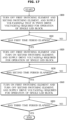
- FIG. 17 is a flowchart illustrating a method for controlling a display device.
- the controller 160 may divide a time for implementing a unit frame into a first time period, a second time period, and a third time period, and control on/off of the switching element 113 for each time period.
- both a first switching element SW1 and a second switching element SW2 may be controlled to be turned off, and thus current may be supplied to both a first LED block Block1 and a second LED block Block2.
- the power supply may supply a voltage 2Vb that is twice a drive voltage Vb required for an operation of a single LED block.
- the above-described process may be continuously performed, and in response to the first time period having elapsed (Yes in 1810), an operation to be described below may be performed.
- the first switching element SW1 may be controlled to be turned off and the second switching element SW2 may be controlled to be turned on, and thus current is supplied only to the first LED block Block1, not to the second LED block Block2.
- the power supply may supply a voltage equivalent to the drive voltage Vb required for an operation of a single LED block.
- the above-described process may be continuously performed, and in response to the second time period having elapsed (Yes in 1830), an operation to be described below may be performed.
- the first switching element SW1 may be controlled to be turned on and the second switching element SW2 may be controlled to be turned off, and thus current is supplied only to the second LED block Block2, not to the first LED block Block1.
- the power supply may supply a voltage equivalent to the drive voltage Vb required for an operation of a single LED block.
- the above-described process may be continuously performed, and in response to the third time period having elapsed (Yes in 1850), the operation is terminated.
- the disclosed embodiments may be embodied in the form of a recording medium storing instructions executable by a computer.
- the instructions may be stored in the form of program code and, when executed by a processor, may generate a program module to perform the operations of the disclosed embodiments.
- the recording medium may be embodied as a computer-readable recording medium.
- the computer-readable recording medium includes all kinds of recording media in which instructions which may be decoded by a computer are stored.
- ROM Read Only Memory
- RAM Random Access Memory
- magnetic tape a magnetic tape
- magnetic disk a magnetic disk
- flash memory a flash memory
- optical data storage device an optical data storage device
Landscapes
- Engineering & Computer Science (AREA)
- Physics & Mathematics (AREA)
- Computer Hardware Design (AREA)
- General Physics & Mathematics (AREA)
- Theoretical Computer Science (AREA)
- Control Of Indicators Other Than Cathode Ray Tubes (AREA)
Applications Claiming Priority (2)
| Application Number | Priority Date | Filing Date | Title |
|---|---|---|---|
| KR1020210096677A KR20230015212A (ko) | 2021-07-22 | 2021-07-22 | 디스플레이 장치 및 그 제어 방법 |
| PCT/KR2022/009327 WO2023003203A1 (fr) | 2021-07-22 | 2022-06-29 | Dispositif d'affichage et procédé de commande correspondant |
Publications (2)
| Publication Number | Publication Date |
|---|---|
| EP4343748A1 true EP4343748A1 (fr) | 2024-03-27 |
| EP4343748A4 EP4343748A4 (fr) | 2024-09-11 |
Family
ID=84980304
Family Applications (1)
| Application Number | Title | Priority Date | Filing Date |
|---|---|---|---|
| EP22846075.4A Pending EP4343748A4 (fr) | 2021-07-22 | 2022-06-29 | Dispositif d'affichage et procédé de commande correspondant |
Country Status (4)
| Country | Link |
|---|---|
| US (1) | US12307950B2 (fr) |
| EP (1) | EP4343748A4 (fr) |
| KR (1) | KR20230015212A (fr) |
| WO (1) | WO2023003203A1 (fr) |
Families Citing this family (3)
| Publication number | Priority date | Publication date | Assignee | Title |
|---|---|---|---|---|
| US12588129B2 (en) | 2023-02-24 | 2026-03-24 | Samsung Electronics Co., Ltd. | Display apparatus and method of controlling the same |
| KR20240131836A (ko) * | 2023-02-24 | 2024-09-02 | 삼성전자주식회사 | 디스플레이 장치 및 그 제어 방법 |
| TWI889406B (zh) * | 2024-06-21 | 2025-07-01 | 錼創顯示科技股份有限公司 | 畫素電路及其顯示亮度的調整方法 |
Family Cites Families (33)
| Publication number | Priority date | Publication date | Assignee | Title |
|---|---|---|---|---|
| KR100864918B1 (ko) | 2001-12-26 | 2008-10-22 | 엘지디스플레이 주식회사 | 액정표시장치의 데이터 구동 장치 |
| JP4754897B2 (ja) | 2004-07-23 | 2011-08-24 | 株式会社半導体エネルギー研究所 | 表示装置及びその駆動方法 |
| KR101246642B1 (ko) | 2004-07-23 | 2013-03-25 | 가부시키가이샤 한도오따이 에네루기 켄큐쇼 | 표시 장치 및 이의 구동 방법 |
| KR101493492B1 (ko) * | 2007-09-14 | 2015-03-06 | 삼성디스플레이 주식회사 | 백라이트 유닛, 이를 포함하는 액정 표시 장치 및 이의구동방법 |
| EP2302706A4 (fr) * | 2008-07-15 | 2012-02-15 | Sharp Kk | Circuit d'attaque d'elements emettant de la lumiere |
| JP2010287601A (ja) * | 2009-06-09 | 2010-12-24 | Panasonic Corp | 発光素子駆動装置 |
| US9351365B2 (en) * | 2009-08-18 | 2016-05-24 | Eldolab Holding B.V. | Control unit for LED assembly and lighting system |
| JP2011204437A (ja) | 2010-03-25 | 2011-10-13 | Sharp Corp | Ledモジュール、led照明装置およびled照明システム |
| KR101110380B1 (ko) * | 2010-12-16 | 2012-02-24 | 이동원 | 교류 구동 엘이디 조명장치 |
| WO2012161528A2 (fr) | 2011-05-26 | 2012-11-29 | 한국전기연구원 | Appareil servant à commander le fonctionnement d'une diode électroluminescente, et procédé associé de commande de courant d'excitation |
| KR20130105212A (ko) | 2012-03-13 | 2013-09-25 | 이동원 | 부하전류를 재사용하는 엘이디 조명장치 |
| RU2627729C2 (ru) | 2012-04-23 | 2017-08-11 | Конинклейке Филипс Н.В. | По отдельности управляемая матрица излучающих элементов |
| KR20140070289A (ko) | 2012-11-30 | 2014-06-10 | 이동원 | 변조지수가 개선된 엘이디 조명장치 |
| KR101473797B1 (ko) * | 2013-05-27 | 2014-12-17 | 포항공과대학교 산학협력단 | Led 균등 점등을 위한 교류 직결형 led 구동 회로 |
| KR101537990B1 (ko) | 2013-06-05 | 2015-07-20 | 한국과학기술원 | 스위치 제어를 이용한 엘이디 조명 장치 |
| US9084321B2 (en) | 2013-07-15 | 2015-07-14 | Shenzhen China Star Optoelectronics Technology Co., Ltd | LED backlight system and display device |
| CN103345903B (zh) | 2013-07-15 | 2015-09-02 | 深圳市华星光电技术有限公司 | 一种led背光系统及显示装置 |
| CN203748048U (zh) * | 2013-10-08 | 2014-07-30 | 吕大明 | Led灯丝稳功率组合驱动器 |
| KR102165446B1 (ko) * | 2013-12-27 | 2020-10-14 | 엘지전자 주식회사 | 발광 다이오드 구동 장치 |
| US9445470B2 (en) * | 2014-06-26 | 2016-09-13 | Dynascan Technology Corp. | LED control circuit with self-adaptive regulation |
| KR101653783B1 (ko) | 2014-08-25 | 2016-09-05 | 주식회사 솔루엠 | 엘이디드라이버 및 그를 이용한 디스플레이 장치 |
| KR102206282B1 (ko) * | 2014-09-05 | 2021-01-22 | 서울반도체 주식회사 | 발광소자 구동회로 및 조명장치 |
| KR20160106973A (ko) | 2015-03-03 | 2016-09-13 | 엘지전자 주식회사 | 조명 디바이스 |
| KR20160126214A (ko) | 2015-04-23 | 2016-11-02 | 주식회사 솔루엠 | 엘이디 드라이버 |
| KR20170059541A (ko) | 2015-11-20 | 2017-05-31 | 삼성디스플레이 주식회사 | 백라이트 유닛 및 이를 포함하는 표시 장치 |
| KR102544173B1 (ko) * | 2016-09-08 | 2023-06-16 | 삼성전자주식회사 | 백라이트 장치 및 백라이트 장치의 제어 방법 |
| CN106658816A (zh) * | 2016-09-26 | 2017-05-10 | 漳州立达信光电子科技有限公司 | 发光二极体装置 |
| KR102792703B1 (ko) | 2016-12-07 | 2025-04-08 | 엘지이노텍 주식회사 | Led 구동 드라이버 및 그 구동방법 |
| JP6988467B2 (ja) | 2017-12-27 | 2022-01-05 | 株式会社デンソー | 車両用前方照明装置、断線検出方法 |
| KR102576149B1 (ko) | 2018-10-16 | 2023-09-08 | 삼성전자주식회사 | 디스플레이 장치 및 그 제어 방법 |
| JP7388991B2 (ja) | 2020-07-22 | 2023-11-29 | 日清紡マイクロデバイス株式会社 | 定電流回路 |
| KR102881828B1 (ko) | 2020-08-26 | 2025-11-07 | 주식회사 엘엑스세미콘 | 엘이디 구동장치 및 엘이디 구동방법 |
| KR20220098339A (ko) | 2020-12-31 | 2022-07-12 | 상하이 센스타임 린강 인텔리전트 테크놀로지 컴퍼니 리미티드 | 차량용 스크린의 제어 방법 및 장치, 전자 기기 및 저장 매체 |
-
2021
- 2021-07-22 KR KR1020210096677A patent/KR20230015212A/ko active Pending
-
2022
- 2022-06-29 WO PCT/KR2022/009327 patent/WO2023003203A1/fr not_active Ceased
- 2022-06-29 EP EP22846075.4A patent/EP4343748A4/fr active Pending
-
2023
- 2023-12-22 US US18/395,105 patent/US12307950B2/en active Active
Also Published As
| Publication number | Publication date |
|---|---|
| EP4343748A4 (fr) | 2024-09-11 |
| US12307950B2 (en) | 2025-05-20 |
| KR20230015212A (ko) | 2023-01-31 |
| WO2023003203A1 (fr) | 2023-01-26 |
| US20240127745A1 (en) | 2024-04-18 |
Similar Documents
| Publication | Publication Date | Title |
|---|---|---|
| US12307950B2 (en) | Display device and method for controlling same | |
| US11501704B2 (en) | Method for sending driving data of backlight source, control circuit and display device | |
| US12062345B2 (en) | Display device and method for controlling the same | |
| US11380247B2 (en) | Display apparatus and method of controlling the same | |
| CN104202545A (zh) | 拼接显示系统、led液晶显示器及电视机 | |
| US20120044272A1 (en) | Display apparatus and driving method of display panel thereof | |
| US9734792B2 (en) | Display device including reset controlling unit and method of driving the same | |
| US20240212637A1 (en) | Display apparatus and control method for same | |
| US8780036B2 (en) | Display apparatus and method for driving backlight applied to the same | |
| US11302273B2 (en) | Display apparatus | |
| US20250201168A1 (en) | Display device and control method thereof | |
| US20260003230A1 (en) | Display apparatus and light apparatus thereof | |
| KR20230163861A (ko) | 디스플레이 장치 및 그 제어방법 | |
| EP4350681A1 (fr) | Dispositif d'affichage et son procédé de commande | |
| KR102639698B1 (ko) | 디스플레이 장치 및 그 제어방법 | |
| US12588129B2 (en) | Display apparatus and method of controlling the same | |
| US12225645B2 (en) | Display apparatus and method of controlling the same | |
| KR102835638B1 (ko) | 디스플레이 장치 및 그의 전원 공유 방법 | |
| US20260093139A1 (en) | Display apparatus | |
| US20240282249A1 (en) | Display apparatus and control method thereof | |
| KR20230171823A (ko) | 디스플레이 장치 및 그 제어 방법 | |
| KR20240131836A (ko) | 디스플레이 장치 및 그 제어 방법 | |
| KR20250114868A (ko) | 디스플레이 장치 및 그 광원 장치 | |
| KR20240134617A (ko) | 디스플레이 장치 | |
| KR20160120848A (ko) | 표시 패널 |
Legal Events
| Date | Code | Title | Description |
|---|---|---|---|
| STAA | Information on the status of an ep patent application or granted ep patent |
Free format text: STATUS: THE INTERNATIONAL PUBLICATION HAS BEEN MADE |
|
| PUAI | Public reference made under article 153(3) epc to a published international application that has entered the european phase |
Free format text: ORIGINAL CODE: 0009012 |
|
| STAA | Information on the status of an ep patent application or granted ep patent |
Free format text: STATUS: REQUEST FOR EXAMINATION WAS MADE |
|
| 17P | Request for examination filed |
Effective date: 20231219 |
|
| AK | Designated contracting states |
Kind code of ref document: A1 Designated state(s): AL AT BE BG CH CY CZ DE DK EE ES FI FR GB GR HR HU IE IS IT LI LT LU LV MC MK MT NL NO PL PT RO RS SE SI SK SM TR |
|
| REG | Reference to a national code |
Ref country code: DE Ref legal event code: R079 Free format text: PREVIOUS MAIN CLASS: G09G0005000000 Ipc: G09G0003320000 |
|
| A4 | Supplementary search report drawn up and despatched |
Effective date: 20240812 |
|
| RIC1 | Information provided on ipc code assigned before grant |
Ipc: H05B 45/10 20200101ALI20240806BHEP Ipc: H05B 45/44 20200101ALI20240806BHEP Ipc: H05B 45/33 20200101ALI20240806BHEP Ipc: H05B 45/325 20200101ALI20240806BHEP Ipc: G09G 5/00 20060101ALI20240806BHEP Ipc: G09G 3/32 20160101AFI20240806BHEP |
|
| DAV | Request for validation of the european patent (deleted) | ||
| DAX | Request for extension of the european patent (deleted) |