EP4343946A1 - Bloc-batterie et ess et véhicule le comprenant - Google Patents
Bloc-batterie et ess et véhicule le comprenant Download PDFInfo
- Publication number
- EP4343946A1 EP4343946A1 EP22916718.4A EP22916718A EP4343946A1 EP 4343946 A1 EP4343946 A1 EP 4343946A1 EP 22916718 A EP22916718 A EP 22916718A EP 4343946 A1 EP4343946 A1 EP 4343946A1
- Authority
- EP
- European Patent Office
- Prior art keywords
- preventing member
- oxygen introduction
- battery pack
- module
- battery
- Prior art date
- Legal status (The legal status is an assumption and is not a legal conclusion. Google has not performed a legal analysis and makes no representation as to the accuracy of the status listed.)
- Granted
Links
Images




Classifications
-
- H—ELECTRICITY
- H01—ELECTRIC ELEMENTS
- H01M—PROCESSES OR MEANS, e.g. BATTERIES, FOR THE DIRECT CONVERSION OF CHEMICAL ENERGY INTO ELECTRICAL ENERGY
- H01M50/00—Constructional details or processes of manufacture of the non-active parts of electrochemical cells other than fuel cells, e.g. hybrid cells
- H01M50/20—Mountings; Secondary casings or frames; Racks, modules or packs; Suspension devices; Shock absorbers; Transport or carrying devices; Holders
- H01M50/204—Racks, modules or packs for multiple batteries or multiple cells
-
- H—ELECTRICITY
- H01—ELECTRIC ELEMENTS
- H01M—PROCESSES OR MEANS, e.g. BATTERIES, FOR THE DIRECT CONVERSION OF CHEMICAL ENERGY INTO ELECTRICAL ENERGY
- H01M50/00—Constructional details or processes of manufacture of the non-active parts of electrochemical cells other than fuel cells, e.g. hybrid cells
- H01M50/30—Arrangements for facilitating escape of gases
- H01M50/317—Re-sealable arrangements
-
- H—ELECTRICITY
- H01—ELECTRIC ELEMENTS
- H01M—PROCESSES OR MEANS, e.g. BATTERIES, FOR THE DIRECT CONVERSION OF CHEMICAL ENERGY INTO ELECTRICAL ENERGY
- H01M10/00—Secondary cells; Manufacture thereof
- H01M10/60—Heating or cooling; Temperature control
- H01M10/61—Types of temperature control
- H01M10/613—Cooling or keeping cold
-
- H—ELECTRICITY
- H01—ELECTRIC ELEMENTS
- H01M—PROCESSES OR MEANS, e.g. BATTERIES, FOR THE DIRECT CONVERSION OF CHEMICAL ENERGY INTO ELECTRICAL ENERGY
- H01M10/00—Secondary cells; Manufacture thereof
- H01M10/60—Heating or cooling; Temperature control
- H01M10/64—Heating or cooling; Temperature control characterised by the shape of the cells
- H01M10/647—Prismatic or flat cells, e.g. pouch cells
-
- H—ELECTRICITY
- H01—ELECTRIC ELEMENTS
- H01M—PROCESSES OR MEANS, e.g. BATTERIES, FOR THE DIRECT CONVERSION OF CHEMICAL ENERGY INTO ELECTRICAL ENERGY
- H01M10/00—Secondary cells; Manufacture thereof
- H01M10/60—Heating or cooling; Temperature control
- H01M10/65—Means for temperature control structurally associated with the cells
- H01M10/656—Means for temperature control structurally associated with the cells characterised by the type of heat-exchange fluid
- H01M10/6561—Gases
-
- H—ELECTRICITY
- H01—ELECTRIC ELEMENTS
- H01M—PROCESSES OR MEANS, e.g. BATTERIES, FOR THE DIRECT CONVERSION OF CHEMICAL ENERGY INTO ELECTRICAL ENERGY
- H01M10/00—Secondary cells; Manufacture thereof
- H01M10/60—Heating or cooling; Temperature control
- H01M10/65—Means for temperature control structurally associated with the cells
- H01M10/656—Means for temperature control structurally associated with the cells characterised by the type of heat-exchange fluid
- H01M10/6561—Gases
- H01M10/6563—Gases with forced flow, e.g. by blowers
-
- H—ELECTRICITY
- H01—ELECTRIC ELEMENTS
- H01M—PROCESSES OR MEANS, e.g. BATTERIES, FOR THE DIRECT CONVERSION OF CHEMICAL ENERGY INTO ELECTRICAL ENERGY
- H01M10/00—Secondary cells; Manufacture thereof
- H01M10/60—Heating or cooling; Temperature control
- H01M10/65—Means for temperature control structurally associated with the cells
- H01M10/656—Means for temperature control structurally associated with the cells characterised by the type of heat-exchange fluid
- H01M10/6561—Gases
- H01M10/6566—Means within the gas flow to guide the flow around one or more cells, e.g. manifolds, baffles or other barriers
-
- H—ELECTRICITY
- H01—ELECTRIC ELEMENTS
- H01M—PROCESSES OR MEANS, e.g. BATTERIES, FOR THE DIRECT CONVERSION OF CHEMICAL ENERGY INTO ELECTRICAL ENERGY
- H01M50/00—Constructional details or processes of manufacture of the non-active parts of electrochemical cells other than fuel cells, e.g. hybrid cells
- H01M50/20—Mountings; Secondary casings or frames; Racks, modules or packs; Suspension devices; Shock absorbers; Transport or carrying devices; Holders
- H01M50/204—Racks, modules or packs for multiple batteries or multiple cells
- H01M50/207—Racks, modules or packs for multiple batteries or multiple cells characterised by their shape
- H01M50/211—Racks, modules or packs for multiple batteries or multiple cells characterised by their shape adapted for pouch cells
-
- H—ELECTRICITY
- H01—ELECTRIC ELEMENTS
- H01M—PROCESSES OR MEANS, e.g. BATTERIES, FOR THE DIRECT CONVERSION OF CHEMICAL ENERGY INTO ELECTRICAL ENERGY
- H01M50/00—Constructional details or processes of manufacture of the non-active parts of electrochemical cells other than fuel cells, e.g. hybrid cells
- H01M50/20—Mountings; Secondary casings or frames; Racks, modules or packs; Suspension devices; Shock absorbers; Transport or carrying devices; Holders
- H01M50/249—Mountings; Secondary casings or frames; Racks, modules or packs; Suspension devices; Shock absorbers; Transport or carrying devices; Holders specially adapted for aircraft or vehicles, e.g. cars or trains
-
- H—ELECTRICITY
- H01—ELECTRIC ELEMENTS
- H01M—PROCESSES OR MEANS, e.g. BATTERIES, FOR THE DIRECT CONVERSION OF CHEMICAL ENERGY INTO ELECTRICAL ENERGY
- H01M50/00—Constructional details or processes of manufacture of the non-active parts of electrochemical cells other than fuel cells, e.g. hybrid cells
- H01M50/20—Mountings; Secondary casings or frames; Racks, modules or packs; Suspension devices; Shock absorbers; Transport or carrying devices; Holders
- H01M50/251—Mountings; Secondary casings or frames; Racks, modules or packs; Suspension devices; Shock absorbers; Transport or carrying devices; Holders specially adapted for stationary devices, e.g. power plant buffering or backup power supplies
-
- H—ELECTRICITY
- H01—ELECTRIC ELEMENTS
- H01M—PROCESSES OR MEANS, e.g. BATTERIES, FOR THE DIRECT CONVERSION OF CHEMICAL ENERGY INTO ELECTRICAL ENERGY
- H01M50/00—Constructional details or processes of manufacture of the non-active parts of electrochemical cells other than fuel cells, e.g. hybrid cells
- H01M50/20—Mountings; Secondary casings or frames; Racks, modules or packs; Suspension devices; Shock absorbers; Transport or carrying devices; Holders
- H01M50/271—Lids or covers for the racks or secondary casings
-
- H—ELECTRICITY
- H01—ELECTRIC ELEMENTS
- H01M—PROCESSES OR MEANS, e.g. BATTERIES, FOR THE DIRECT CONVERSION OF CHEMICAL ENERGY INTO ELECTRICAL ENERGY
- H01M50/00—Constructional details or processes of manufacture of the non-active parts of electrochemical cells other than fuel cells, e.g. hybrid cells
- H01M50/30—Arrangements for facilitating escape of gases
- H01M50/317—Re-sealable arrangements
- H01M50/325—Re-sealable arrangements comprising deformable valve members, e.g. elastic or flexible valve members
-
- H—ELECTRICITY
- H01—ELECTRIC ELEMENTS
- H01M—PROCESSES OR MEANS, e.g. BATTERIES, FOR THE DIRECT CONVERSION OF CHEMICAL ENERGY INTO ELECTRICAL ENERGY
- H01M50/00—Constructional details or processes of manufacture of the non-active parts of electrochemical cells other than fuel cells, e.g. hybrid cells
- H01M50/30—Arrangements for facilitating escape of gases
- H01M50/35—Gas exhaust passages comprising elongated, tortuous or labyrinth-shaped exhaust passages
- H01M50/367—Internal gas exhaust passages forming part of the battery cover or case; Double cover vent systems
-
- H—ELECTRICITY
- H01—ELECTRIC ELEMENTS
- H01M—PROCESSES OR MEANS, e.g. BATTERIES, FOR THE DIRECT CONVERSION OF CHEMICAL ENERGY INTO ELECTRICAL ENERGY
- H01M50/00—Constructional details or processes of manufacture of the non-active parts of electrochemical cells other than fuel cells, e.g. hybrid cells
- H01M50/30—Arrangements for facilitating escape of gases
- H01M50/383—Flame arresting or ignition-preventing means
-
- H—ELECTRICITY
- H01—ELECTRIC ELEMENTS
- H01M—PROCESSES OR MEANS, e.g. BATTERIES, FOR THE DIRECT CONVERSION OF CHEMICAL ENERGY INTO ELECTRICAL ENERGY
- H01M2220/00—Batteries for particular applications
- H01M2220/10—Batteries in stationary systems, e.g. emergency power source in plant
-
- H—ELECTRICITY
- H01—ELECTRIC ELEMENTS
- H01M—PROCESSES OR MEANS, e.g. BATTERIES, FOR THE DIRECT CONVERSION OF CHEMICAL ENERGY INTO ELECTRICAL ENERGY
- H01M2220/00—Batteries for particular applications
- H01M2220/20—Batteries in motive systems, e.g. vehicle, ship, plane
-
- Y—GENERAL TAGGING OF NEW TECHNOLOGICAL DEVELOPMENTS; GENERAL TAGGING OF CROSS-SECTIONAL TECHNOLOGIES SPANNING OVER SEVERAL SECTIONS OF THE IPC; TECHNICAL SUBJECTS COVERED BY FORMER USPC CROSS-REFERENCE ART COLLECTIONS [XRACs] AND DIGESTS
- Y02—TECHNOLOGIES OR APPLICATIONS FOR MITIGATION OR ADAPTATION AGAINST CLIMATE CHANGE
- Y02E—REDUCTION OF GREENHOUSE GAS [GHG] EMISSIONS, RELATED TO ENERGY GENERATION, TRANSMISSION OR DISTRIBUTION
- Y02E60/00—Enabling technologies; Technologies with a potential or indirect contribution to GHG emissions mitigation
- Y02E60/10—Energy storage using batteries
Definitions
- the present disclosure relates to a battery pack, and an energy storage system (ESS) and a vehicle including the battery pack.
- ESS energy storage system
- a battery pack applied to a device such as an energy storage system (ESS) or an electric vehicle may be manufactured to include a plurality of battery modules to which high-power and high-capacity lithium secondary batteries are applied.
- ESS energy storage system
- the number of lithium secondary batteries included in one battery module may be increased and the number of battery modules included in one battery pack may be increased.
- a fire occurring in a battery pack starts from an abnormal temperature increase and generation of internal gas of a lithium secondary battery in a battery module.
- a temperature of a lithium secondary battery abnormally rises, internal gas is generated, and internal pressure of the lithium secondary battery increases to a certain level or more, venting occurs in the lithium secondary battery, and thus, high-temperature gas is ejected to the outside of the lithium secondary battery, and a high-temperature spark including an electrode active material and aluminum particles is ejected.
- a fire may occur.
- venting gas generated during a thermal event
- venting gas may be discharged at an appropriate speed despite high initial venting pressure, to prevent generation of negative pressure due to a rapid decrease in the venting pressure.
- the amount of oxygen introduced into a battery pack may be minimized even when negative pressure is generated as venting pressure decreases.
- the present disclosure is designed to solve the problems of the related art, and therefore the present disclosure is directed to providing a battery pack configured to minimize generation of negative pressure due to a rapid decrease in venting pressure by discharging venting gas, generated during a thermal event, at an appropriate speed.
- the present disclosure is also directed to providing a battery pack configured to minimize the amount of oxygen introduced into the battery pack even when negative pressure is generated as venting pressure decreases.
- a battery pack includes a module assembly including a plurality of battery modules each including, on a side, a module opening through which venting gas is discharged, a pack cover facing the module opening and configured to cover the side of the module assembly, and an oxygen introduction preventing member located in a space formed between the module assembly and the pack cover and configured to prevent oxygen from being reversely introduced after venting gas is discharged in an extension direction of the space.
- the battery pack may further include a pack opening provided at at least one of both ends of the space in the extension direction.
- a plurality of oxygen introduction preventing members may be provided, wherein the plurality of oxygen introduction preventing members are spaced apart from each other in the extension direction of the space.
- the oxygen introduction preventing member may be located between a pair of battery modules that are adjacent to each other in the space.
- the space may include a plurality of partition spaces divided by the oxygen introduction preventing member, wherein the oxygen introduction preventing member has a structure that is opened and closed to allow or block flow of a fluid between adjacent partition spaces.
- the oxygen introduction preventing member may be configured to be opened when pressure of a fluid flowing in the extension direction of the space is equal to or higher than reference pressure.
- the oxygen introduction preventing member may be an opening/closing door configured to be rotatable.
- the oxygen introduction preventing member may be a valve having a partially cut structure to be opened and closed.
- the oxygen introduction preventing member may be configured to be opened only in one direction.
- the module opening may include a first module opening provided on a side of each battery module and a second module opening provided on the other side.
- the pack cover may include a first pack cover provided on a side of the module assembly and a second pack cover provided on the other side.
- the battery pack may further include a first pack opening formed at one of both ends of a space formed between the first pack cover and the module assembly in the extension direction, and a second pack opening formed at the other end opposite to the one of both ends of a space formed between the second pack cover and the module assembly in the extension direction.
- the oxygen introduction preventing member may include a first oxygen introduction preventing member located in a first space formed between the first pack cover and the module assembly and a second oxygen introduction preventing member located in a second space formed between the second pack cover and the module assembly.
- An energy storage system (ESS) may include the battery pack of the present disclosure.
- a vehicle according to an embodiment of the present disclosure may include the battery pack of the present disclosure.
- venting gas generated during a thermal event may be discharged at an appropriate speed, and thus, generation of negative pressure due to a rapid decrease in venting pressure may be minimized.
- the amount of oxygen introduced into a battery pack may be minimized even when negative pressure is generated as venting pressure decreases, and thus, a fire may be prevented.
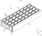
- a battery pack 1 includes a module assembly M, a pack cover 20, and an oxygen introduction preventing member 30.
- the module assembly M may include a plurality of battery modules 10 each including, on a side, a module opening P through which venting gas may be discharged.
- the pack cover 20 may face the module opening P to cover the side of the module assembly M.
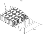
- the oxygen introduction preventing member 30 may be located in a space S formed between the module assembly M and the pack cover 20.
- the oxygen introduction preventing member 30 may be configured to prevent oxygen from being reversely introduced after venting gas is discharged in an extension direction (direction parallel to an X axis) of the space.
- a flow of venting gas discharged from the battery module 10 due to a thermal event and along the extension direction of the space S may be delayed.
- a discharge flow of venting gas is appropriately delayed in this way, generation of negative pressure due to a great decrease in pressure at the late stage of discharge compared to pressure at the initial stage of discharge of the venting gas may be minimized or prevented.
- a high-temperature spark material e.g., an electrode active material or aluminum metal particles
- high-temperature venting gas and the high-temperature spark material meet oxygen
- a fire may occur.
- the battery pack 1 of the present disclosure may prevent an explosion due to an abnormal increase in internal pressure of the battery pack 1 through discharge of venting gas and may prevent a large amount of oxygen from being introduced due to generation of a lot of negative pressure from the outside into the battery pack 1 by preventing a sudden change in venting gas discharge pressure. Accordingly, because a fire is prevented from occurring when ignitable materials and oxygen meet each other, safety in use of a secondary battery may be greatly improved.
- FIG. 3 is a view illustrating a shape of the battery module 10, according to the present disclosure.
- the battery module 10 may include a cell assembly including a plurality of battery cells 100, a module housing 200 in which the cell assembly is accommodated, and a cover frame 300 configured to cover an open side of the module housing 200.
- the battery cell 100 may include an electrode lead 110 connected to an electrode assembly (not shown) therein and drawn out of a cell case.
- the battery cell 100 may be, for example, a pouch-type battery cell.
- the module housing 200 may have a shape with at least one open side.
- the electrode lead 110 may extend toward the open side of the module housing 200.
- the cover frame 300 may include a lead slit through which the electrode lead 110 passes.
- a bus bar may be located on the cover frame 300, and each of a plurality of electrode leads 110 may pass through the lead slit and may be coupled to the bus bar.
- a module opening P that is a gap through which venting gas generated in the battery module 10 may be discharged may be formed between the lead slit and the electrode lead 110.
- the module opening P may function as a path through which a cooling fluid (e.g., air) may be introduced when the battery pack 1 is normally used, and may function as a path through which venting gas is discharged when venting gas is generated due to a thermal event.
- a cooling fluid e.g., air
- a plurality of battery modules 10 may be arranged so that the module openings P face the same direction.
- the module opening P may be formed in a plane (X-Z plane) facing the pack cover 20 of the present disclosure.
- the pack cover 20 may be configured to cover a side of the module assembly M.
- the pack cover 20 may be coupled to the module assembly M.
- the pack cover 20 may face the module opening P of the battery module 10.
- the pack cover 20 may be spaced apart from the module assembly M by a certain distance so that the space S for a flow of venting gas discharged from the module opening P of the battery module 10 is formed.
- the pack cover 20 may extend in an arrangement direction (direction parallel to the X axis) of the plurality of battery modules 10.
- the battery pack 1 of the present disclosure includes the pack cover 20 as described above, venting gas and a spark material that may be discharged from each of the plurality of battery modules 10 may be blocked. Also, when venting gas is discharged from at least some of the plurality of battery modules 10 included in the module assembly M, the pack cover may guide the venting gas to be discharged in a desired direction.
- the oxygen introduction preventing member 30 may be configured to allow the flow of a cooling fluid and the flow of venting gas, and to block the introduction of oxygen due to negative pressure.
- the oxygen introduction preventing member 30 will be described below in detail with reference to the drawings.
- the battery pack 1 may include a pack opening A (see FIG. 1 ).
- the pack opening A may be provided at at least one of both ends of the space S formed between the module assembly M and the pack cover 20 in the extension direction (direction parallel to the X axis).
- the battery pack 1 may discharge venting gas discharged through the module opening P and flowing in the extension direction of the space S to the outside. Accordingly, an explosion of the battery pack 1 due to an increase in internal pressure of the battery pack 1 as venting gas is generated may be prevented.
- a plurality of oxygen introduction preventing members 30 may be provided.
- the plurality of oxygen introduction preventing members 30 may be spaced apart from each other in the extension direction of the space S.
- the oxygen introduction preventing member 30 may be located between a pair of battery modules 10 that are adjacent to each other in the space S. According to this arrangement of the oxygen introduction preventing members 30, when venting gas is discharged from any one of adjacent battery modules 10, the venting gas may be prevented from being easily introduced into the neighboring battery module 10.
- smooth discharge of venting gas through the module opening P may not be hindered.
- each of the plurality of oxygen introduction preventing members 30 is located at a position corresponding to a gap between a pair of adj acent battery modules 10 in the space S, smooth discharge of venting gas through the module opening P may be maintained, and rapid discharge of venting gas in the extension direction of the space S may be well suppressed.
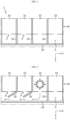
- the space S formed between the pack cover 20 and the module assembly M may include a plurality of partition spaces divided by the oxygen introduction preventing members 30.
- the oxygen introduction preventing member 30 may have a structure that may be opened and closed to allow or block the flow of a fluid between adjacent partition spaces.
- the oxygen introduction preventing member 30 may be configured to be opened when pressure of a fluid flowing in the extension direction of the space S is equal to or higher than a reference level.
- the oxygen introduction preventing member 30 may be configured to be opened by circulation pressure of a cooling fluid.
- the oxygen introduction preventing member 30 may be configured to be opened by discharge pressure of venting gas at the initial stage of venting due to a thermal event, and not to be opened by venting pressure that decreases when a certain time elapses after the venting occurs.
- reference pressure at which the oxygen introduction preventing member 30 may be opened may be lower than circulation pressure (first pressure) of a cooling fluid and discharge pressure (second pressure) of venting gas at the initial stage of venting, and may be higher than discharge pressure (third pressure) of venting gas when a certain period of time elapses after the venting.
- the reference pressure for opening the oxygen introduction preventing member 30 When the reference pressure for opening the oxygen introduction preventing member 30 is set as described above, smooth cooling may be maintained and the introduction of oxygen due to rapid discharge of venting gas may be prevented.
- sufficient circulation pressure of a cooling fluid may be generated by driving of a device for cooling the battery pack 1 (e.g., a fan for circulating cooling air) by considering the reference pressure. Accordingly, smooth cooling may be possible even when the oxygen introduction preventing member 30 is applied.
- venting gas of a secondary battery When venting gas of a secondary battery is discharged due to a thermal event, the venting gas is discharged at a very high pressure at the initial stage of discharge and then discharge pressure decreases as the amount of internal gas decreases. Accordingly, internal pressure may be reduced according to appropriate discharge of venting gas by adjusting the reference pressure at which the oxygen introduction preventing member 30 may be opened, and the introduction of oxygen due to generation of negative pressure due to a rapid decrease in pressure may also be prevented.
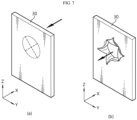
- FIGS. 6 and 7 are views illustrating a shape of the oxygen introduction preventing member 30, according to the present disclosure.
- the oxygen introduction preventing member 30 may be an opening/closing door configured to be rotatable.
- the oxygen introduction preventing member 30 may be coupled to, for example, an edge of the battery module 10.
- the opening/closing door may be hinged to the battery module 10.
- the opening/closing door may be configured to, when operating from a state, that is, a closed state, in which the space S is divided to an open state, receive an elastic restoring force to return to the closed state again.
- a hinge applied to rotate the oxygen introduction preventing member may be a spring hinge.
- discharge of venting gas may be appropriately adjusted by adjusting an elastic modulus of a spring applied to the spring hinge.
- the elastic modulus of the spring is too large, it is difficult to discharge venting gas, and when the elastic modulus of the spring is too small, it is difficult to prevent rapid discharge of venting gas, thereby making it difficult to prevent reverse introduction of oxygen due to negative pressure.
- the oxygen introduction preventing member 30 may be a valve having a partially cut structure to be opened and closed.
- the oxygen introduction preventing member 30 may be coupled to, for example, an edge of the battery module 10.
- opening pressure may be determined according to an area occupied by a cut portion relative to a total area, a thickness of a component used as the valve, and material properties applied to the component used as the valve.
- the valve includes an elastic material such as resin, the valve may be opened by venting pressure that is equal to or higher than reference pressure, and as the venting gas is discharged and discharge pressure of the venting gas decreases, the valve may be slowly closed by an elastic restoring force.
- the oxygen introduction preventing member 30 of the present disclosure may be provided as an opening/closing door and/or a valve. Also, the oxygen introduction preventing member 30 may be configured to have an elastic restoring force, and thus, a degree of opening of the oxygen introduction preventing member 30 may be proportional to a magnitude of applied pressure. As such, the battery pack 1 of the present disclosure may be configured to allow smooth cooling by applying cooling fluid circulation pressure for completely opening the oxygen introduction preventing member 30. Also, in the battery pack 1 of the present disclosure, the oxygen introduction preventing member 30 may be completely opened by high pressure at the initial stage of discharge of venting gas to rapidly reduce internal pressure, and as discharge pressure of gas decreases, the oxygen introduction preventing member 30 may be slowly closed to block the introduction of oxygen.
- the oxygen introduction preventing member 30 may be configured to be opened only in one direction.
- the oxygen introduction preventing member 30 may be a one-way opening/closing door or a one-way opening/closing valve.
- the oxygen introduction preventing member 30 is configured to be opened only in a discharge direction of venting gas and not to be opened in the opposite direction, even when discharge pressure of venting gas decreases, the oxygen introduction preventing member 30 is only closed and may not be opened in the reverse direction. Accordingly, reverse introduction of oxygen due to a decrease in discharge pressure of venting gas is impossible.
- the module opening P may include a first module opening P1 provided on a side of each battery module 10 and a second module opening P2 provided on the other side.
- the pack cover 20 may include a first pack cover 20A provided on a side of the module assembly M and a second pack cover 20B provided on the other side. In this case, venting gas discharged through one side of the battery module 10 and venting gas discharged through the other side may be guided to flow in the arrangement direction (direction parallel to the X axis) of the plurality of battery modules 10.
- the battery pack 1 of the present disclosure may include a first pack opening A1 and a second pack opening A2.
- the first pack opening A1 may be formed at one of both ends of a space S 1 formed between the first pack cover 20A and the module assembly M in the extension direction (direction parallel to the X axis).
- the second pack opening A2 may be formed at the other end opposite to the one of both ends of a space S2 formed between the second pack cover 20A and the module assembly M in the extension direction.
- any one of the first pack opening A1 and the second pack opening A2 may be used as an inlet of a cooling fluid and the other may be used as an outlet of the cooling fluid.
- a cooling fluid may directly pass through the inside of the plurality of battery modules 10, thereby achieving effective cooling (see a movement path of a cooling fluid in an arrow direction of FIG. 10 ).
- the oxygen introduction preventing member 30 of the present disclosure may be provided in each of the first space S1 formed between one side of the module assembly M and the first pack cover 20A and the second space S2 formed between the other side of the module assembly M and the second pack cover 20B.
- the oxygen introduction preventing member 30 provided in the first space S1 may be configured to be opened toward the second pack opening A2 as the cooling fluid flows.
- the oxygen introduction preventing member 30 may be configured to be opened when pressure of a fluid is equal to or higher than reference pressure. Accordingly, when a cooling fluid is circulated at a pressure equal to or higher than the reference pressure, the oxygen introduction preventing member 30 may be opened and cooling of the battery pack 1 may be smoothly performed.
- venting gas discharged through the first module opening P1 may cause the oxygen introduction preventing member 30 located in the first space S1 to be opened toward the first pack opening A1. Accordingly, the venting gas may be discharged to the outside of the battery pack 1 through the first pack opening A1. Venting gas discharged through the second module opening P2 may cause the oxygen introduction preventing member 30 located in the second space S2 to be opened toward the second pack opening A2. Accordingly, the venting gas may be discharged through the second pack opening A2. As time elapses after the venting gas is discharged, venting pressure may decrease, and thus, the oxygen introduction preventing member 30 may be slowly closed to prevent oxygen from being reversely introduced.
- both the first pack opening A1 used as an inlet of a cooling fluid and the second pack opening A2 used as an outlet may function as openings for discharging venting gas. That is, a discharge direction of a cooling fluid and a discharge direction of venting gas may not be the same.
- the oxygen introduction preventing member 30 when configured to be opened only in one direction, a discharge direction of a cooling fluid and a discharge direction of venting gas are the same.
- the oxygen introduction preventing member 30 located in the first space S1 when the first pack opening A1 functions as an inlet of a cooling fluid and the second pack opening A2 functions as an outlet of the cooling fluid, the oxygen introduction preventing member 30 located in the first space S1 may be configured to be opened only in a direction opposite to the first pack opening A1, and the oxygen introduction preventing member 30 located in the second space S2 may be configured to be opened only in a direction toward the second pack opening A2.
- venting gas from the battery module 10 may be discharged through the second module opening P2.
- Venting gas introduced into the second space S2 through the second module opening P2 may be discharged to the outside of the battery pack 1 through the second pack opening A2.
- the oxygen introduction preventing member 30 located in the second space S2 may be opened toward the second pack opening A2 due to high venting pressure, to discharge venting gas.
- venting pressure may decrease, the oxygen introduction preventing member 30 in the second space S2 may be slowly closed, and thus, oxygen may be blocked from being reversely introduced through the second pack opening A2.
- the oxygen introduction preventing member 30 located in the first space S1 may be maintained in a closed state.
- an energy storage system (ESS) 3 may include the battery pack 1 according to the present disclosure.
- the ESS 3 may include a battery system including a plurality of battery packs 1 and a rack housing 2 in which the plurality of battery packs 1 may be stacked.
- the ESS 3 may include one or more battery systems.
- a vehicle 5 may include the battery pack 1 according to the present disclosure.
- the vehicle 5 may be driven by receiving power from one or more battery packs 1.
- the vehicle 5 may be, for example, an electric vehicle (EV) or a hybrid electric vehicle (HEV).
- EV electric vehicle
- HEV hybrid electric vehicle
Landscapes
- Chemical & Material Sciences (AREA)
- Chemical Kinetics & Catalysis (AREA)
- Electrochemistry (AREA)
- General Chemical & Material Sciences (AREA)
- Engineering & Computer Science (AREA)
- Manufacturing & Machinery (AREA)
- Aviation & Aerospace Engineering (AREA)
- Battery Mounting, Suspending (AREA)
- Gas Exhaust Devices For Batteries (AREA)
- Secondary Cells (AREA)
Applications Claiming Priority (2)
| Application Number | Priority Date | Filing Date | Title |
|---|---|---|---|
| KR20210188647 | 2021-12-27 | ||
| PCT/KR2022/021440 WO2023128577A1 (fr) | 2021-12-27 | 2022-12-27 | Bloc-batterie et ess et véhicule le comprenant |
Related Child Applications (1)
| Application Number | Title | Priority Date | Filing Date |
|---|---|---|---|
| EP26153397.0 Division-Into | 2026-01-22 |
Publications (3)
| Publication Number | Publication Date |
|---|---|
| EP4343946A1 true EP4343946A1 (fr) | 2024-03-27 |
| EP4343946A4 EP4343946A4 (fr) | 2025-03-05 |
| EP4343946B1 EP4343946B1 (fr) | 2026-04-01 |
Family
ID=86999962
Family Applications (1)
| Application Number | Title | Priority Date | Filing Date |
|---|---|---|---|
| EP22916718.4A Active EP4343946B1 (fr) | 2021-12-27 | 2022-12-27 | Bloc-batterie et ess et véhicule le comprenant |
Country Status (7)
| Country | Link |
|---|---|
| US (1) | US20240380069A1 (fr) |
| EP (1) | EP4343946B1 (fr) |
| JP (2) | JP7729976B2 (fr) |
| KR (2) | KR102660087B1 (fr) |
| CN (2) | CN222483617U (fr) |
| AU (1) | AU2022429255A1 (fr) |
| WO (1) | WO2023128577A1 (fr) |
Families Citing this family (1)
| Publication number | Priority date | Publication date | Assignee | Title |
|---|---|---|---|---|
| KR20250072762A (ko) * | 2023-11-17 | 2025-05-26 | 주식회사 엘지에너지솔루션 | 배터리 팩 및 이를 포함하는 자동차 |
Family Cites Families (11)
| Publication number | Priority date | Publication date | Assignee | Title |
|---|---|---|---|---|
| KR101191660B1 (ko) * | 2010-11-08 | 2012-10-17 | 에스비리모티브 주식회사 | 전지 모듈 |
| WO2012133710A1 (fr) * | 2011-03-31 | 2012-10-04 | 三洋電機株式会社 | Alimentation électrique et véhicule la comprenant |
| JP2013037794A (ja) * | 2011-08-04 | 2013-02-21 | Sanyo Electric Co Ltd | バッテリー装置 |
| WO2018023050A1 (fr) * | 2016-07-29 | 2018-02-01 | Crynamt Management Llc | Bloc-batterie haute densité |
| KR102322910B1 (ko) * | 2017-07-31 | 2021-11-05 | 주식회사 엘지에너지솔루션 | 배터리 케이스와 이를 포함하는 배터리 팩 및 자동차 |
| KR102086842B1 (ko) * | 2018-10-22 | 2020-03-10 | 현대이엔티 주식회사 | Ess 배터리랙 화재확산방지 장치 |
| KR102400818B1 (ko) | 2019-03-06 | 2022-05-20 | 주식회사 엘지에너지솔루션 | 열폭주 현상 발생 시 모듈 내부로 공기 유입을 막을 수 있는 구조를 갖는 배터리 모듈 및 이를 포함하는 배터리 팩 |
| CN210110904U (zh) * | 2019-09-19 | 2020-02-21 | 宁德时代新能源科技股份有限公司 | 下箱体、电池包及车辆 |
| KR102752589B1 (ko) * | 2019-11-07 | 2025-01-08 | 주식회사 엘지에너지솔루션 | 배터리 모듈 |
| KR102814566B1 (ko) * | 2020-04-01 | 2025-05-29 | 주식회사 엘지에너지솔루션 | 가스 차단 구조체를 포함하는 전지모듈 |
| CN212011077U (zh) * | 2020-04-30 | 2020-11-24 | 昆山宝创新能源科技有限公司 | 软包电池模组防护罩 |
-
2022
- 2022-12-27 EP EP22916718.4A patent/EP4343946B1/fr active Active
- 2022-12-27 WO PCT/KR2022/021440 patent/WO2023128577A1/fr not_active Ceased
- 2022-12-27 CN CN202421158047.6U patent/CN222483617U/zh active Active
- 2022-12-27 KR KR1020220186269A patent/KR102660087B1/ko active Active
- 2022-12-27 AU AU2022429255A patent/AU2022429255A1/en active Pending
- 2022-12-27 US US18/688,835 patent/US20240380069A1/en active Pending
- 2022-12-27 CN CN202290000413.8U patent/CN221176561U/zh active Active
- 2022-12-27 JP JP2024504856A patent/JP7729976B2/ja active Active
-
2024
- 2024-04-12 KR KR1020240049293A patent/KR102778354B1/ko active Active
-
2025
- 2025-08-13 JP JP2025134824A patent/JP2025161859A/ja active Pending
Also Published As
| Publication number | Publication date |
|---|---|
| AU2022429255A1 (en) | 2023-12-21 |
| JP7729976B2 (ja) | 2025-08-26 |
| JP2025161859A (ja) | 2025-10-24 |
| EP4343946B1 (fr) | 2026-04-01 |
| EP4343946A4 (fr) | 2025-03-05 |
| JP2024529442A (ja) | 2024-08-06 |
| CN221176561U (zh) | 2024-06-18 |
| KR20240054246A (ko) | 2024-04-25 |
| CN222483617U (zh) | 2025-02-14 |
| KR102660087B1 (ko) | 2024-04-23 |
| WO2023128577A1 (fr) | 2023-07-06 |
| KR102778354B1 (ko) | 2025-03-10 |
| KR20230099695A (ko) | 2023-07-04 |
| US20240380069A1 (en) | 2024-11-14 |
Similar Documents
| Publication | Publication Date | Title |
|---|---|---|
| US12374752B2 (en) | Battery pack | |
| EP4290665B1 (fr) | Bloc-batterie présentant une sécurité améliorée | |
| US12315953B2 (en) | Battery pack and vehicle including the same | |
| EP4383432A1 (fr) | Bloc-batterie et véhicule le comprenant | |
| EP4287379A1 (fr) | Module de batterie | |
| US20240079716A1 (en) | Traction battery pack venting assembly and method of establishing a traction battery pack vent path | |
| EP4258447A1 (fr) | Bloc-batterie et dispositif le comprenant | |
| EP4379937A1 (fr) | Bloc-batterie et véhicule le comprenant | |
| EP4343946A1 (fr) | Bloc-batterie et ess et véhicule le comprenant | |
| US12283712B2 (en) | Battery pack and vehicle including the same | |
| EP4379935A1 (fr) | Bloc-batterie, et système de stockage d'énergie (ess) et véhicule le comprenant | |
| US20250149729A1 (en) | Battery pack and vehicle including the same | |
| US20260074355A1 (en) | Battery pack and vehicle including the same | |
| US20260038962A1 (en) | Battery pack amd vehicle including same | |
| EP4475315A1 (fr) | Module de batterie ayant une unité de séparation et de décharge de matériau de décharge, et bloc-batterie le comprenant | |
| KR20240074454A (ko) | 안전성이 강화된 배터리 모듈 | |
| KR20250054581A (ko) | 배터리 팩 |
Legal Events
| Date | Code | Title | Description |
|---|---|---|---|
| STAA | Information on the status of an ep patent application or granted ep patent |
Free format text: STATUS: THE INTERNATIONAL PUBLICATION HAS BEEN MADE |
|
| PUAI | Public reference made under article 153(3) epc to a published international application that has entered the european phase |
Free format text: ORIGINAL CODE: 0009012 |
|
| STAA | Information on the status of an ep patent application or granted ep patent |
Free format text: STATUS: REQUEST FOR EXAMINATION WAS MADE |
|
| 17P | Request for examination filed |
Effective date: 20231222 |
|
| AK | Designated contracting states |
Kind code of ref document: A1 Designated state(s): AL AT BE BG CH CY CZ DE DK EE ES FI FR GB GR HR HU IE IS IT LI LT LU LV MC ME MK MT NL NO PL PT RO RS SE SI SK SM TR |
|
| A4 | Supplementary search report drawn up and despatched |
Effective date: 20250204 |
|
| RIC1 | Information provided on ipc code assigned before grant |
Ipc: H01M 10/6566 20140101ALI20250129BHEP Ipc: H01M 10/6563 20140101ALI20250129BHEP Ipc: H01M 10/647 20140101ALI20250129BHEP Ipc: H01M 50/102 20210101ALI20250129BHEP Ipc: H01M 50/35 20210101AFI20250129BHEP |
|
| DAV | Request for validation of the european patent (deleted) | ||
| DAX | Request for extension of the european patent (deleted) | ||
| STAA | Information on the status of an ep patent application or granted ep patent |
Free format text: STATUS: EXAMINATION IS IN PROGRESS |
|
| 17Q | First examination report despatched |
Effective date: 20250805 |
|
| GRAP | Despatch of communication of intention to grant a patent |
Free format text: ORIGINAL CODE: EPIDOSNIGR1 |
|
| STAA | Information on the status of an ep patent application or granted ep patent |
Free format text: STATUS: GRANT OF PATENT IS INTENDED |
|
| INTG | Intention to grant announced |
Effective date: 20251119 |
|
| P01 | Opt-out of the competence of the unified patent court (upc) registered |
Free format text: CASE NUMBER: UPC_APP_0015372_4343946/2025 Effective date: 20251201 |
|
| GRAS | Grant fee paid |
Free format text: ORIGINAL CODE: EPIDOSNIGR3 |
|
| GRAA | (expected) grant |
Free format text: ORIGINAL CODE: 0009210 |
|
| STAA | Information on the status of an ep patent application or granted ep patent |
Free format text: STATUS: THE PATENT HAS BEEN GRANTED |
|
| AK | Designated contracting states |
Kind code of ref document: B1 Designated state(s): AL AT BE BG CH CY CZ DE DK EE ES FI FR GB GR HR HU IE IS IT LI LT LU LV MC ME MK MT NL NO PL PT RO RS SE SI SK SM TR |
|
| REG | Reference to a national code |
Ref country code: CH Ref legal event code: F10 Free format text: ST27 STATUS EVENT CODE: U-0-0-F10-F00 (AS PROVIDED BY THE NATIONAL OFFICE) Effective date: 20260401 Ref country code: GB Ref legal event code: FG4D |
|
| REG | Reference to a national code |
Ref country code: IE Ref legal event code: FG4D |
|
| REG | Reference to a national code |
Ref country code: DE Ref legal event code: R096 Ref document number: 602022033785 Country of ref document: DE |