EP4344084B1 - Antennenumschaltverfahren, endgerätevorrichtung und kommunikationsvorrichtung - Google Patents
Antennenumschaltverfahren, endgerätevorrichtung und kommunikationsvorrichtung Download PDFInfo
- Publication number
- EP4344084B1 EP4344084B1 EP24157400.3A EP24157400A EP4344084B1 EP 4344084 B1 EP4344084 B1 EP 4344084B1 EP 24157400 A EP24157400 A EP 24157400A EP 4344084 B1 EP4344084 B1 EP 4344084B1
- Authority
- EP
- European Patent Office
- Prior art keywords
- srs resource
- srs
- resource set
- resources
- set group
- Prior art date
- Legal status (The legal status is an assumption and is not a legal conclusion. Google has not performed a legal analysis and makes no representation as to the accuracy of the status listed.)
- Active
Links
Images
Classifications
-
- H—ELECTRICITY
- H04—ELECTRIC COMMUNICATION TECHNIQUE
- H04B—TRANSMISSION
- H04B7/00—Radio transmission systems, i.e. using radiation field
- H04B7/02—Diversity systems; Multi-antenna system, i.e. transmission or reception using multiple antennas
- H04B7/04—Diversity systems; Multi-antenna system, i.e. transmission or reception using multiple antennas using two or more spaced independent antennas
- H04B7/08—Diversity systems; Multi-antenna system, i.e. transmission or reception using multiple antennas using two or more spaced independent antennas at the receiving station
- H04B7/0802—Diversity systems; Multi-antenna system, i.e. transmission or reception using multiple antennas using two or more spaced independent antennas at the receiving station using antenna selection
- H04B7/0805—Diversity systems; Multi-antenna system, i.e. transmission or reception using multiple antennas using two or more spaced independent antennas at the receiving station using antenna selection with single receiver and antenna switching
- H04B7/0814—Diversity systems; Multi-antenna system, i.e. transmission or reception using multiple antennas using two or more spaced independent antennas at the receiving station using antenna selection with single receiver and antenna switching based on current reception conditions, e.g. switching to different antenna when signal level is below threshold
-
- H—ELECTRICITY
- H04—ELECTRIC COMMUNICATION TECHNIQUE
- H04B—TRANSMISSION
- H04B7/00—Radio transmission systems, i.e. using radiation field
- H04B7/02—Diversity systems; Multi-antenna system, i.e. transmission or reception using multiple antennas
- H04B7/04—Diversity systems; Multi-antenna system, i.e. transmission or reception using multiple antennas using two or more spaced independent antennas
- H04B7/06—Diversity systems; Multi-antenna system, i.e. transmission or reception using multiple antennas using two or more spaced independent antennas at the transmitting station
- H04B7/0686—Hybrid systems, i.e. switching and simultaneous transmission
- H04B7/0691—Hybrid systems, i.e. switching and simultaneous transmission using subgroups of transmit antennas
-
- H—ELECTRICITY
- H04—ELECTRIC COMMUNICATION TECHNIQUE
- H04B—TRANSMISSION
- H04B7/00—Radio transmission systems, i.e. using radiation field
- H04B7/02—Diversity systems; Multi-antenna system, i.e. transmission or reception using multiple antennas
- H04B7/04—Diversity systems; Multi-antenna system, i.e. transmission or reception using multiple antennas using two or more spaced independent antennas
- H04B7/08—Diversity systems; Multi-antenna system, i.e. transmission or reception using multiple antennas using two or more spaced independent antennas at the receiving station
- H04B7/0868—Hybrid systems, i.e. switching and combining
- H04B7/0874—Hybrid systems, i.e. switching and combining using subgroups of receive antennas
-
- H—ELECTRICITY
- H04—ELECTRIC COMMUNICATION TECHNIQUE
- H04L—TRANSMISSION OF DIGITAL INFORMATION, e.g. TELEGRAPHIC COMMUNICATION
- H04L5/00—Arrangements affording multiple use of the transmission path
- H04L5/0001—Arrangements for dividing the transmission path
- H04L5/0014—Three-dimensional division
- H04L5/0023—Time-frequency-space
-
- H—ELECTRICITY
- H04—ELECTRIC COMMUNICATION TECHNIQUE
- H04L—TRANSMISSION OF DIGITAL INFORMATION, e.g. TELEGRAPHIC COMMUNICATION
- H04L5/00—Arrangements affording multiple use of the transmission path
- H04L5/003—Arrangements for allocating sub-channels of the transmission path
- H04L5/0048—Allocation of pilot signals, i.e. of signals known to the receiver
- H04L5/0051—Allocation of pilot signals, i.e. of signals known to the receiver of dedicated pilots, i.e. pilots destined for a single user or terminal
-
- H—ELECTRICITY
- H04—ELECTRIC COMMUNICATION TECHNIQUE
- H04L—TRANSMISSION OF DIGITAL INFORMATION, e.g. TELEGRAPHIC COMMUNICATION
- H04L5/00—Arrangements affording multiple use of the transmission path
- H04L5/003—Arrangements for allocating sub-channels of the transmission path
- H04L5/0053—Allocation of signalling, i.e. of overhead other than pilot signals
-
- H—ELECTRICITY
- H04—ELECTRIC COMMUNICATION TECHNIQUE
- H04L—TRANSMISSION OF DIGITAL INFORMATION, e.g. TELEGRAPHIC COMMUNICATION
- H04L5/00—Arrangements affording multiple use of the transmission path
- H04L5/0091—Signalling for the administration of the divided path, e.g. signalling of configuration information
- H04L5/0094—Indication of how sub-channels of the path are allocated
-
- H—ELECTRICITY
- H04—ELECTRIC COMMUNICATION TECHNIQUE
- H04W—WIRELESS COMMUNICATION NETWORKS
- H04W52/00—Power management, e.g. Transmission Power Control [TPC] or power classes
- H04W52/04—Transmission power control [TPC]
- H04W52/06—TPC algorithms
- H04W52/14—Separate analysis of uplink or downlink
- H04W52/146—Uplink power control
-
- H—ELECTRICITY
- H04—ELECTRIC COMMUNICATION TECHNIQUE
- H04W—WIRELESS COMMUNICATION NETWORKS
- H04W52/00—Power management, e.g. Transmission Power Control [TPC] or power classes
- H04W52/04—Transmission power control [TPC]
- H04W52/30—Transmission power control [TPC] using constraints in the total amount of available transmission power
- H04W52/32—TPC of broadcast or control channels
- H04W52/325—Power control of control or pilot channels
Definitions
- the present application relates to the communication field, and more particularly, to an antenna switching method, a terminal device, and a communication device.
- MIMO Multiple Input Multiple Output
- various kinds of gains can be obtained, e.g. a space diversity gain, a beamforming gain (also referred to as a pre-coding gain), a space multiplexing gain.
- a transmitter needs to determine a beamforming matrix/pre-coding matrix for signal transmission.
- a basic requirement is to obtain some form of channel information of a transmission channel corresponding to the terminal.
- a channel reciprocity method in order to obtain the channel information of the transmission channel of the terminal, a channel reciprocity method may be adopted.
- the channel reciprocity method needs the terminal to transmit a Sounding Reference Signal (SRS) according to configuration information from a base station, and the configuration information is related to an antenna switching configuration of the terminal.
- the antenna switching configuration may be represented by xTyR or txry, wherein x and y are positive integers, specifically indicating that the SRS may be transmitted through x antenna ports, and y corresponds to the number of all or part of the receiving antennas of a terminal device.
- the terminal may improve a downlink receiving capability with more receiving antennas.
- the antenna switching configuration, xTyR, of the terminal device has a large value of y, for example, y is greater than 4. At present, there is no suitable configuration mode to support antenna switching for these terminal devices which have more (such as more than 4) receiving antennas.
- US 2019/253214 A1 (LIU LE [USJ ET AL.), 15 August 2019 , discloses aspects directed towards sounding reference signal (SRS) antenna switching.
- SRS sounding reference signal
- an SRS configuration is received from a network in which at least four antennas of a scheduled entity are configured based on the SRS configuration.
- the SRS configuration configures at least one antenna to simultaneously support SRS antenna switching and an uplink (UL) multiple-input multiple-output (MIMO) communication.
- An SRS communication is then transmitted according to the SRS configuration.
- a transmission capability reporting is received form a scheduled entity comprising at least four antennas.
- a determination is then made of whether the scheduled entity may simultaneously support SRS antenna switching and an UL MIMO communication.
- An SRS configuration is then generated for the scheduled entity based on the determination in which a default SRS configuration configures at least one antenna to simultaneously support the SRS antenna switching and the UL MIMO communication.
- WO 2018/126474 A1 provides methods and apparatus for transmitting multiplexed sounding reference signal (SRS) ports in communication systems operating according to new radio (NR) technologies.
- An exemplary method includes obtaining an indication of a technique to use in transmitting sounding reference signals (SRS) via five or more antenna ports in one slot and transmitting the SRS via the five or more antenna ports according to the indicated technique.
- SRS sounding reference signals
- a base station may determine an antenna switching capability of a user equipment (UE).
- the antenna switching capability indicates a number of RX antenna ports of the UE.
- the base station schedules a number of SRS resource sets for the UE based at least in part on the number of RX antenna ports in excess of four. For example, the number of RX antenna ports may be equal to (8). As another example, the number of RX antenna ports may be equal to (6).
- the base station further receives, from the UE, uplink transmissions of one or more SRS resources for each of the scheduled SRS resource sets.
- Embodiments of the present application provide an antenna switching method, carried out by a network device, according to independent claim 1, and a corresponding apparatus for a network device, according to independent claim 9.
- GSM Global System of Mobile Communication
- CDMA Code Division Multiple Access
- WCDMA Wideband Code Division Multiple Access
- GPRS General Packet Radio Service
- LTE Long Term Evolution
- LTE-A Advanced Long Term Evolution
- NR New Radio
- UMTS Universal Mobile Telecommunications System
- WLAN Wireless Local Area Networks
- WiFi Wireless Fidelity
- 5G next generation communication
- D2D Device to Device
- M2M Machine to Machine
- MTC Machine Type Communication
- V2V Vehicle to Vehicle
- a communication system in the embodiments of the present application may be applied to a Carrier Aggregation (CA) scenario, or a Dual Connectivity (DC) scenario, or a Standalone (SA) network deployment scenario.
- CA Carrier Aggregation
- DC Dual Connectivity
- SA Standalone
- a frequency spectrum to which an embodiment of the present application is applied is not limited.
- the embodiment of the present application may be applied to a licensed spectrum, or an unlicensed spectrum.
- the terminal device may also be referred to as a User Equipment (UE), an access terminal, a subscriber unit, a subscriber station, a mobile station, a mobile platform, a remote station, a remote terminal, a mobile device, a user terminal, a terminal, a wireless communication device, a user agent, or a user apparatus, etc.
- UE User Equipment
- the terminal device may be a STATION (ST) in the WLAN, or may be a cellular phone, a cordless phone, a Session Initiation Protocol (SIP) phone, a Wireless Local Loop (WLL) station, a Personal Digital Assistant (PDA) device, a handheld device with a wireless communication function, a computing device, or another processing device connected to a wireless modem, a vehicle-mounted device, a wearable device, or a next generation communication system, e.g., a terminal device in an NR network, or a terminal device in a future evolved Public Land Mobile Network (PLMN).
- ST STATION
- PDA Personal Digital Assistant
- the terminal device may also be a wearable device.
- the wearable device may also be referred to as a wearable smart device, which is a general term of wearable devices, e.g., glasses, gloves, a watch, clothing, or shoes, which are intelligent designed for daily wear and developed by using wearing technologies.
- the wearable device is a portable device that is worn directly on a body, or integrated into clothes or an accessory of a user.
- the wearable device is not only a hardware device, but also achieves powerful functions through software support, data interaction, and cloud interaction.
- Generalized wearable smart devices include a device that is full functioned, large sized, and may achieve complete or partial functions without relying on a smart phone, such as a smart watch, or smart glasses, and include a device that only focuses on a kind of application function, and needs to be used in conjunction with another device such as a smart phone, such as various types of smart bracelets, smart jewelry, or the like, for monitoring physical signs.
- the network device may be a device configured to communicate with a mobile device, and may be an Access Point (AP) in WLAN, or a Base Transceiver Station (BTS) in GSM or CDMA, or may be a NodeB (NB) in WCDMA, or an Evolutional Node B (eNB or eNodeB) in LTE, or a relay station or an access point, or a vehicle-mounted device, a wearable device, a network device (gNB) in an NR network, or a network device in a future evolved PLMN network, etc.
- AP Access Point
- BTS Base Transceiver Station
- NB NodeB
- eNB or eNodeB Evolutional Node B
- gNB network device
- gNB network device
- gNB network device in an NR network
- future evolved PLMN network etc.
- a network device provides a service for a cell
- a terminal device communicates with the network device through a transmission resource (e.g., a frequency domain resource, or referred to as a spectrum resource) used for the cell
- a transmission resource e.g., a frequency domain resource, or referred to as a spectrum resource
- the cell may be a cell corresponding to the network device (e.g., a base station).
- the cell may belong to a macro base station, or a base station corresponding to a Small cell.
- the Small cell here may include: a Metro cell, a Micro cell, a Pico cell, or a Femto cell, etc. These Small cells have characteristics of a small coverage range and a low transmission power, and are suitable for providing high-speed data transmission services.
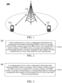
- FIG. 1 exemplarily illustrates one network device 110 and two terminal devices 120.
- a wireless communication system 100 may include a plurality of network devices 110, and another quantity of terminal devices may be included within a coverage range of each network device 110, which is not limited in the embodiments of the present application.
- Embodiments of the present application may be applied to one terminal device 120 and one network device 110, and may also be applied to one terminal device 120 and another terminal device 120.
- the wireless communication system 100 may further include another network entity such as a Mobility Management Entity (MME), and an Access and Mobility Management Function (AMF), which is not limited in the embodiments of the present application.
- MME Mobility Management Entity
- AMF Access and Mobility Management Function
- FIG. 2 is a flow chart of an implementation of an antenna switching method according to an embodiment of the present application, including the following act S210.
- a first terminal device receives configuration information, the configuration information indicates M Surrounding Reference Signal (SRS) resource set groups, each of which contains at least one SRS resource set; wherein M is a positive integer; and each SRS resource set group corresponds to a corresponding antenna switching configuration that supports a first terminal device to have more than four receiving antennas.
- SRS Surrounding Reference Signal
- the antenna switching configuration is represented by xTyR; wherein y is an integer greater than 4 and x is a positive integer; xTyR indicates that the SRS may be transmitted by x antenna ports, y corresponds to the number of all or part of receiving antennas of the first terminal device.
- the antenna port may refer to a transmitting antenna.
- the SRS resource set group may represent one or more SRS resource sets.
- One or more SRS resource sets may be regarded as one whole, which is referred to as for short an SRS resource set group, and it is not necessary to define one or more SRS resource sets as an SRS resource set group.
- the SRS resource set group contains one SRS resource set. That is, the corresponding SRS resource set group is equal to the SRS resource set (the SRS resource set group contains only one SRS resource set).
- resourceType fields corresponding to SRS resource sets in different SRS resource set groups are configured to be different values.
- resourceType fields corresponding to SRS resource sets in different SRS resource set groups are configured to be a same value or different values.
- the configuration information is sent from a network device to the first terminal device.
- the configuration information is sent from another terminal device (such as a second terminal device) to the first terminal device, which can better support communication between terminals, such as Device-to-Device (D2D) communication, Vehicle to Everything (V2X) communication, or Sidelink communication.
- D2D Device-to-Device
- V2X Vehicle to Everything
- Sidelink communication such as Sidelink communication
- the first terminal device reports an antenna switching capability that supports the antenna switching configuration represented by the xTyR.
- the antenna switching capability can also be referred to as an antenna switching capability corresponding to xTyR.
- the first terminal device may report the antenna switching capability via Radio Resource Control (RRC) signaling.
- RRC Radio Resource Control
- M 1, 2, or 3 therefore more configurations can be supported, flexibility of a system configuration can be improved, and system performance can be improved.
- the M SRS resource set groups contain at least one first SRS resource set group, and the first SRS resource set group corresponds to an antenna switching configuration corresponding to 8T8R; wherein, the first SRS resource set group contains one SRS resource set; each SRS resource set contains one SRS resource, and each SRS resource is configured with eight SRS ports.
- the M SRS resource set groups contain at least one second SRS resource set group, and the second SRS resource set group corresponds to an antenna switching configuration corresponding to 4T8R; wherein, the second SRS resource set group contains one SRS resource set, each SRS resource set contains two SRS resources, and each SRS resource is configured with four SRS ports.
- the M SRS resource set groups contain at least one third SRS resource set group, and the third SRS resource set group corresponds to an antenna switching configuration corresponding to 2T8R; if a resourceType field corresponding to an SRS resource set in the third SRS resource set group is configured to be periodic or semipersistent, the third SRS resource set group contains one SRS resource set, and the SRS resource set contains four SRS resources, and each SRS resource is configured with two SRS ports.
- the M SRS resource set groups contain at least one fourth SRS resource set group, and the fourth SRS resource set group corresponds to an antenna switching configuration corresponding to 2T8R. If a resourceType field corresponding to an SRS resource set in the fourth SRS resource set group is configured to be aperiodic, then: the fourth SRS resource set group contains two SRS resource sets, and each SRS resource set contains two SRS resources, each SRS resource is configured with 2 SRS ports, SRS resources in different SRS resource sets are transmitted on different slots, and SRS resources in a same resource set are transmitted on different symbols of a same slot; or, the fourth SRS resource set group contains two SRS resource sets, one of the two SRS resource set contains one SRS resource and the other SRS resource set contains three SRS resources, each SRS resource is configured with 2 SRS ports; SRS resources in different SRS resource sets are transmitted on different slots, and SRS resources in a same resource set are transmitted on different symbols of a same slot; or, the fourth SRS resource set group contains one SRSRS resource
- the M SRS resource set groups contain at least one fifth SRS resource set group, and the fifth SRS resource set group corresponds to an antenna switching configuration corresponding to 1T8R.
- the fifth SRS resource set group contains one SRS resource set.
- the SRS resource set contains eight SRS resources. Each SRS resource is configured with one SRS port.
- the M SRS resource set groups contain at least one sixth SRS resource set group, and the sixth SRS resource set group corresponds to an antenna switching configuration corresponding to 1T8R.
- the sixth SRS resource set group contains two SRS resource sets, the two SRS resource sets contain eight SRS resources in total (for example, each of the two SRS resource sets contains four SRS resources, respectively), each SRS resource is configured with one SRS port; SRS resources in different SRS resource sets are transmitted on different slots, and SRS resources in a same resource set are transmitted on different symbols of a same slot; or, the sixth SRS resource set group contains three SRS resource sets, the three SRS resource sets contain eight SRS resources (for example, the three SRS resource sets contains three, three and two SRS resources, respectively), each SRS resource is configured with one SRS port; SRS resources in different SRS resource sets are transmitted on different slots, and SRS resources in a same resource set are transmitted on different symbols of a same slot; or, the sixth SRS resource set group contains four SRS resource sets, the four SRS resource sets contain eight SRS resources in total (for example, each of the two SRS resource sets contains four SRS resources, respectively), each SRS resource is configured with one SRS port; S
- the M SRS resource set groups contain at least one seventh SRS resource set group, and the seventh SRS resource set group corresponds to an antenna switching configuration corresponding to 4T6R; each seventh SRS resource set group contains one SRS resource set.
- Each SRS resource set contains two SRS resources, one of the two SRS resources is configured with four SRS ports, and the other SRS resource set is configured with two SRS ports; or, each SRS resource set contains three SRS resources, each SRS resource is configured with two SRS ports.
- the M SRS resource set groups contain at least one eighth SRS resource set group, and the eighth SRS resource set group corresponds to an antenna switching configuration corresponding to 2T6R.
- the eighth SRS resource set group contains one SRS resource set, and the SRS resource set contains three SRS resources, and each SRS resource is configured with two SRS ports.
- the M SRS resource set groups contain at least one ninth SRS resource set group, and the ninth SRS resource set group corresponds to an antenna switching configuration corresponding to 2T6R.
- the ninth SRS resource set group contains one SRS resource set, the SRS resource set contains three SRS resources, and each SRS resource is configured with two SRS ports; or, the ninth SRS resource set group contains two SRS resource sets; one of the two SRS resource sets contains one SRS resource and the other SRS resource set contains two SRS resources, each SRS resource is configured with 2 SRS ports; SRS resources in different SRS resource sets are transmitted on different slots, and SRS resources in a same resource set are transmitted on different symbols of a same slot.
- the M SRS resource set groups contain at least one tenth SRS resource set group, and the tenth SRS resource set group corresponds to an antenna switching configuration corresponding to 1T6R.
- the tenth SRS resource set group contains one SRS resource set, and the SRS resource set contains six SRS resources, and each SRS resource is configured with one SRS port.
- the M SRS resource set groups contain at least one eleventh SRS resource set group, and the eleventh SRS resource set group corresponds to an antenna switching configuration corresponding to 1T6R.
- the eleventh SRS resource set group contains two SRS resource sets; the two SRS resource sets contain six SRS resources in total (for example, each of the two SRS resource sets contains three SRS resources, respectively), each SRS resource is configured with one SRS port; SRS resources in different SRS resource sets are transmitted on different slots, and SRS resources in a same resource set are transmitted on different symbols of a same slot; or, the eleventh SRS resource set group contains three SRS resource sets; the three SRS resource sets contain six SRS resources in total (for example, each of the three SRS resource sets contains two SRS resources), each SRS resource is configured with one SRS port; SRS resources in different SRS resource sets are transmitted on different slots, and SRS resources in a same resource set are transmitted on different symbols of a same slot; or, the eleventh SRS resource set group contains one SRS resource set, the SRS resource set contains six SRS resources,
- the first terminal device does not transmit other signals on Y symbols of a guard period between adjacent SRS resources, wherein Y is a positive integer.
- Y may correspond to different values according to different subcarrier spacings, that is, the value of Y is determined according to the subcarrier spacing.
- the value of Y may be specified according to a protocol.
- the value of Y is determined according to a first UE capability reported by the first terminal device; for another part of the subcarriers, the value of Y may be specified according to the protocol.
- this method can reduce the guard period and system overhead for UE with strong capability; on the other hand, this method can reduce the implementation complexity and/or cost of UE with low capability, which is convenient for the popularization of the UE with low capability.
- a guard period between SRS resources transmitted on different slots in a same SRS resource set is at least greater than, or is equal to or greater than Y symbols.
- a guard period between SRS resources in different SRS resource sets in a same SRS resource set group is at least greater than, or is equal to or greater than Y symbols.
- a guard period between SRS resources in different SRS resource sets is at least greater than, or is equal to or greater than Y symbols.
- the predetermined threshold value and the predetermined value may be specified by the protocol.
- an SRS resource contained in the SRS resource set occupies all or part of the symbols of one slot, specifically may occupy at least one symbol in the last six symbols of one slot.
- the symbol(s) occupied by the SRS resource may be determined according to a second UE capability reported by the first terminal device. In this way, different resources may be allocated for UEs with different capabilities, so that an SRS capacity can be improved.
- the second UE capability is used to indicate available symbol information that the first terminal device may use for SRS resource configuration in one slot. For example, it indicates that all 14 symbols of one slot may support the SRS resource configuration, or it indicates that the last 8 symbols of one slot may support the SRS resource configuration.
- the SRS resource contained in the SRS resource set occupies at least one of the last six symbols of one slot. In other words, when the UE does not report a stronger capability, a capability supported by a terminal in the existing protocol is used by default.
- the network device or the second terminal device can obtain more complete channels between itself and the first terminal device, assisting in pre-coding determination, and improving communication performance between each other.
- SRS ports for an SRS resource(s) in one SRS resource set group correspond to different antenna ports of the first terminal device.
- the configuration information corresponds to a third UE capability reported by the first terminal device.
- the third UE capability indicates that the first terminal device has an antenna switching capability corresponding to xTyR; wherein there is at least one y, which takes one of 6 and 8, in the xTyR corresponding to the antenna switching capability, or there is at least one y, which takes 8, in the xTyR corresponding to the antenna switching capability.
- y may be one of 1, 2, 4.
- y may be one of 1, 2, 4, 6, 8; and there is at least one y that is equal to 6, or at least one y that is equal to one of 6 and 8.
- a Usage field in the RRC Information Element (IE) corresponding to the SRS resource set is configured to be AntennaSwitching.
- a resourceType field corresponding to at least one SRS resource set in one SRS resource set group is configured to be a same value.
- the resourceType field may be configured to one of the following: aperiodic, semiPersistent, periodic.
- a subcarrier spacing corresponding to an SRS resource in an SRS resource set is:
- the first terminal device does not support the antenna switching capability corresponding to xTyR (y > 4) when the subcarrier spacing is larger than the first threshold; or, the first terminal device does not support the antenna switching capability corresponding to xTyR (y > 6) when the subcarrier spacing is larger than the first threshold.
- the first threshold corresponds to a subcarrier spacing of 120KHz.
- a part or all of the following power parameters corresponding to the plurality of SRS resource sets are the same: alpha; p0; pathlossReferenceRS; and srs-Power Control Adjustment States.
- the method further includes: the first terminal device sends an SRS signal according to the configuration information.
- the network device or the second terminal device receives the SRS signal sent by the first terminal device, then the network device or the second terminal device performs measurement according to the received SRS signal, determines a pre-coding matrix corresponding to the first terminal device, and transmits a corresponding Physical Downlink Shared Channel (PDSCH) or Physical Downlink Control Channel (PDCCH) or another channel or a signal.
- PDSCH Physical Downlink Shared Channel
- PDCCH Physical Downlink Control Channel
- the present embodiment may support a terminal which is of 8 receiving antennas and 8 transmitting antennas (hereinafter referred to as a first terminal A).
- SRS resource set groups (hereinafter referred to as SRS resource set groups) indicated by the configuration information at least contain one SRS resource set group corresponding to 8T8R antenna switching configuration.
- M SRS resource set groups may be configured for the first terminal A, each SRS resource set group contains only one SRS resource set, resourceType values corresponding to SRS resource sets in different SRS resource set groups are different, each SRS resource set contains one SRS resource, and each SRS resource is configured with eight SRS ports.
- the present embodiment may support a terminal which is of 8 receiving antennas and 4 transmitting antennas (hereinafter referred to as a first terminal A).
- SRS resource set groups indicated by the configuration information at least contain one SRS resource set group corresponding to 4T8R antenna switching configuration.
- the first terminal A may be configured with M SRS resource set groups.
- the present embodiment may support a terminal which is of 8 receiving antennas and 2 transmitting antennas (hereinafter referred to as a first terminal A).
- SRS resource set groups indicated by the configuration information at least contain one SRS resource set group corresponding to 2T8R antenna switching configuration.
- the first terminal A may be configured with M SRS resource set groups.
- the present embodiment may support a terminal which is of 8 receiving antennas and 1 transmitting antennas (hereinafter referred to as a first terminal A).
- SRS resource set groups indicated by the configuration information at least contain one SRS resource set group corresponding to 1T8R antenna switching configuration.
- the first terminal A may be configured with M SRS resource set groups.
- the present embodiment may support a terminal which is of 6 receiving antennas and 4 transmitting antennas (hereinafter referred to as a first terminal A).
- SRS resource set groups indicated by the configuration information at least contain one SRS resource set group corresponding to 4T6R antenna switching configuration.
- the first terminal A can be configured with M SRS resource set groups.
- the present embodiment may support a terminal which is of 6 receiving antennas and 2 transmitting antennas (hereinafter referred to as a first terminal A).
- SRS resource set groups indicated by the configuration information at least contain one SRS resource set group corresponding to 2T6R antenna switching configuration.
- the first terminal A can be configured with M SRS resource set groups.
- the present embodiment may support a terminal which is of 6 receiving antennas and 1 transmitting antennas (hereinafter referred to as a first terminal A).
- SRS resource set groups indicated by the configuration information at least contain one SRS resource set group corresponding to 1T6R antenna switching configuration.
- the first terminal A may be configured with M SRS resource set groups.
- FIG. 3 is a flow chart of an implementation of another antenna switching method according to an embodiment of the present application, including the following act S310.
- a communication device sends configuration information; the configuration information indicates M Surrounding Reference Signal (SRS) resource set groups, each of which contains at least one SRS resource set; wherein M is a positive integer; each SRS resource set group corresponds to a corresponding antenna switching configuration that supports a first terminal device to have more than four receiving antennas.
- SRS Surrounding Reference Signal
- the antenna switching configuration is represented by xTyR; wherein y is an integer greater than 4 and x is a positive integer; xTyR indicates that the SRS supports transmission by x antenna ports, y corresponds to the number of all or part of receiving antennas of the first terminal device.
- the communication device is a network device or a second terminal device.
- the communication device sends the configuration information to the first terminal device.
- the communication device receives an antenna switching capability reported by the first terminal device, and the antenna switching capability supports the antenna switching configuration represented by the xTyR.
- the communication device receives the antenna switching capability reported by the first terminal through an RRC signaling.
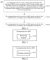
- FIG. 4 is a flow chart of an implementation of another antenna switching method according to an embodiment of the present application. As shown in FIG. 4 , the act S310 may be followed by acts S420 and S430.
- the communication device receives an SRS signal sent by the first terminal device according to the configuration information.
- a pre-coding matrix or a beamforming matrix of the first terminal device is determined according to the SRS signal.
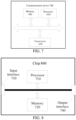
- FIG. 5 is a schematic diagram of a structure of a terminal device 500 according to an embodiment of the present application.
- the terminal device 500 includes: a receiving module 510, which is configured to receive configuration information; wherein the configuration information indicates M Surrounding Reference Signal (SRS) resource set groups, each of which contains at least one SRS resource set; wherein M is a positive integer; each SRS resource set group corresponds to a corresponding antenna switching configuration that supports a first terminal device to have more than four receiving antennas.
- SRS Surrounding Reference Signal
- the antenna switching configuration is represented by xTyR; wherein y is an integer greater than 4 and x is a positive integer; xTyR indicates that the SRS supports transmission by x antenna ports, y corresponds to the number of all or part of receiving antennas of the first terminal device.
- FIG. 6 is a schematic diagram of a structure of a communication device 600 according to an embodiment of the present application.
- the communication device 600 includes: a sending module 611, which is configured to send configuration information; wherein the configuration information indicates M Surrounding Reference Signal (SRS) resource set groups, each of which contains at least one SRS resource set; wherein M is a positive integer; each SRS resource set group corresponds to a corresponding antenna switching configuration that supports a first terminal device to have more than four receiving antennas.
- SRS Surrounding Reference Signal
- the antenna switching configuration is represented by xTyR; wherein y is an integer greater than 4 and x is a positive integer; xTyR indicates that the SRS supports transmission by x antenna ports, y corresponds to the number of all or part of receiving antennas of the first terminal device.
- the communication device may be a network device or a terminal device.
- FIG. 7 is a schematic diagram of a structure of a communication device 700 according to an embodiment of the present application.
- the communication device 700 shown in FIG. 7 includes a processor 610, which may invoke and run a computer program from a memory to implement any of the methods in the embodiments of the present application.
- the communication device 700 may further include a memory 620.
- the processor 610 may invoke and run a computer program from the memory 620 to implement any of the methods in the embodiments of the present application.
- the memory 620 may be a separate device independent of the processor 610, or may be integrated in the processor 610.
- the communication device 700 may further include a transceiver 630, and the processor 610 may control the transceiver 630 to communicate with another device.
- the transceiver 630 may send information or data to another device or receive information or data sent by another device.
- the transceiver 630 may include a transmitter and a receiver.
- the transceiver 630 may further include antennas, a quantity of which may be one or more.
- the communication device 700 may be the first terminal device according to the embodiments of the present application, and the communication device 700 may implement corresponding flows implemented by the first terminal device in various methods of the embodiments of the present application, which will not be repeated here for brevity.
- the communication device 700 may be a communication device according to the embodiments of the present application (such as the network device or the second terminal device), and the communication device 700 may implement corresponding flows implemented by the communication device in various methods according to the embodiments of the present application, which will not be repeated here for brevity.
- FIG. 8 is a schematic diagram of a structure of a chip 800 according to an embodiment of the present application.
- the chip 800 shown in FIG. 8 includes a processor 710, wherein the processor 710 may invoke and run a computer program from a memory to implement any of the methods in the embodiments of the present application.
- the chip 800 may further include a memory 720.
- the processor 710 may invoke and run a computer program from the memory 720 to implement any of the methods in the embodiments of the present application.
- the memory 720 may be a separate device independent of the processor 710, or may be integrated in the processor 710.
- the chip 700 may further include an input interface 730.
- the processor 710 may control the input interface 730 to communicate with another device or chip. Specifically, the processor 710 may acquire information or data sent by another device or chip.
- the chip 700 may further include an output interface 740.
- the processor 710 may control the output interface 740 to communicate with another device or chip. Specifically, the processor 710 may output information or data to another device or chip.
- the chip may be applied to the first terminal device in the embodiments of the present application, and the chip may implement the corresponding flows implemented by the first terminal device in various methods of the embodiments of the present application, which will not be repeated here for brevity.
- the chip may be applied to a communication device in the embodiment of the present application, such as the network device or the second terminal device, and the chip may implement corresponding flows implemented by the communication device in various methods according to the embodiments of the present application, which will not be repeated here for brevity.
- chip mentioned in the embodiments of the present application may also be referred to as a system-level chip, a system chip, a chip system, or a system on chip, etc.
- the above-mentioned processor may be a general purpose processor, a Digital Signal Processor (DSP), a Field Programmable Gate Array (FPGA), an Application Specific Integrated Circuit (ASIC) or another programmable logic device, a transistor logic device, or a discrete hardware component, etc.
- DSP Digital Signal Processor
- FPGA Field Programmable Gate Array
- ASIC Application Specific Integrated Circuit
- the above-mentioned general-purpose processor may be a microprocessor or any conventional processor, etc.
- the above-mentioned memory may be a volatile memory or non-volatile memory, or may include both volatile and non-volatile memories.
- the non-volatile memory may be a Read-Only Memory (ROM), a Programmable ROM (PROM), an Erasable PROM (EPROM), an Electrically EPROM (EEPROM), or a flash memory.
- the volatile memory may be a Random Access Memory (RAM).
- the foregoing memories are examples for illustration and should not be construed as limitations.
- the memory in the embodiment of the present application may be a Static RAM (SRAM), a Dynamic RAM (DRAM), a Synchronous DRAM (SDRAM), a Double Data Rate SDRAM (DDR SDRAM), an Enhanced SDRAM (ESDRAM), a Synch Link DRAM (SLDRAM), and a Direct Rambus RAM (DR RAM), etc. That is to say, the memories in the embodiments of the present application are intended to include, but are not limited to, these and any other suitable types of memories.
- the above-mentioned embodiments may be implemented in whole or in part through software, hardware, firmware, or any combination thereof.
- When implemented through software they may be implemented in whole or in part in a form of a computer program product.
- the computer program product includes one or more computer instructions.
- the computer program instructions When the computer program instructions are loaded and executed on a computer, flows or functions described in the embodiments of the present application are generated in whole or in part.
- the computer may be a general purpose computer, a special purpose computer, a computer network, or another programmable apparatus.
- the computer instructions may be stored in a computer-readable storage medium, or transmitted from one computer-readable storage medium to another computer-readable storage medium, for example, the computer instructions may be transmitted from a website site, a computer, a server, or a data center to another website site, computer, server, or data center through a wired mode (e.g., a coaxial cable, an optical fiber, and a Digital Subscriber Line (DSL)) or a wireless mode (e.g., infrared radiation, radio, and microwave).
- the computer-readable storage medium may be any available medium that can be accessed by a computer or a data storage device such as a server, a data center, or the like that integrates one or more available media.
- the available media may be magnetic media (e.g., floppy disks, hard disks, magnetic tapes), optical media (e.g., Digital Versatile Disks (DVDs)), or semiconductor media (e.g., Solid State Disks (SSDs)), or the like.
- magnetic media e.g., floppy disks, hard disks, magnetic tapes
- optical media e.g., Digital Versatile Disks (DVDs)
- DVDs Digital Versatile Disks
- semiconductor media e.g., Solid State Disks (SSDs)
- sequence numbers of the various processes do not imply an order of execution of the various processes, which should be determined by their functions and internal logics, but should not constitute any limitation on implementation processes of the embodiments of the present application.
Landscapes
- Engineering & Computer Science (AREA)
- Signal Processing (AREA)
- Computer Networks & Wireless Communication (AREA)
- Mobile Radio Communication Systems (AREA)
Claims (15)
- Antennenschaltverfahren (300), ausgeführt durch eine Netzwerkvorrichtung, ausgelegt für den Betrieb in einem Funkkommunikationssystem gemäß dem 3GPP-Standard, das Verfahren umfassend:Senden (310) von Konfigurationsinformationen an eine erste Endgerätevorrichtung;wobei die Konfigurationsinformationen M Sondierungsreferenzsignal(SRS)-Ressourcensatzgruppen angeben, von denen jede mindestens einen SRS-Ressourcensatz enthält; wobei M eine positive Ganzzahl ist;wobei jede der SRS-Ressourcensatzgruppen einer entsprechenden Antennenschaltkonfiguration entspricht, die es der ersten Endgerätevorrichtung ermöglicht, mehr als vier Empfangsantennen aufzuweisen;wobei die Antennenschaltkonfiguration durch xTyR dargestellt wird; wobei y eine Ganzzahl größer als 4 ist und x eine positive Ganzzahl ist; xTyR angibt, dass ein SRS die Übertragung über x Antennenanschlüsse unterstützt, und y einer Anzahl aller oder eines Teils der Empfangsantennen der ersten Endgerätevorrichtung entspricht;wobei das Antennenschaltverfahren ferner umfasst: Empfangen einer ersten Antennenumschaltfähigkeit, die von der ersten Endgerätevorrichtung gemeldet wird, und wobei die erste Fähigkeit die durch xTyR dargestellte Antennenschaltkonfiguration unterstützt;wobei, wenn eine Vielzahl von SRS-Ressourcen in einem SRS-Ressourcensatz auf demselben Schlitz von der ersten Endgerätevorrichtung empfangen werden, andere Signale von der ersten Endgerätevorrichtung nicht auf Y Symbolen einer Schutzperiode zwischen benachbarten SRS-Ressourcen empfangen werden, wobei Y eine positive Ganzzahl ist;wobei ein Wert für Y einem Subcarrier-Abstand entsprechend bestimmt wird;wenn der Wert für Y größer als ein vorgegebener Schwellenwert oder gleich einem vorgegebenen Wert ist, ist eine Schutzperiode zwischen SRS-Ressourcen in unterschiedlichen SRS-Ressourcensätzen in derselben SRS-Ressourcensatzgruppe mindestens Y Symbolen entspricht;wobei ein konfigurierbarer Wert eines resourceType-Felds, das einem SRS-Ressourcensatz entspricht, aperiodisch, semipersistent oder periodisch ist; und M gleich 1, 2 oder 3 ist,Empfangen (S420) eines von der ersten Endgerätevorrichtung gesendeten SRS-Signals gemäß den Konfigurationsinformationen.
- Verfahren nach Anspruch 1, wobei, wenn ein resourceType-Feld, das einem in einer SRS-Ressourcensatzgruppe enthaltenen SRS-Ressourcensatz entspricht, als periodisch oder semipersistent ausgelegt ist, die SRS-Ressourcensatzgruppe einen SRS-Ressourcensatz enthält.
- Verfahren nach Anspruch 1, wobei
wenn x nicht gleich y ist, resourceType-Felder, die den SRS-Ressourcensätzen verschiedener SRS-Ressourcensatzgruppen entsprechen, so ausgelegt werden, dass sie unterschiedliche Werte aufweisen. - Verfahren nach einem der Ansprüche 1 bis 3, wobei die M SRS-Ressourcensatzgruppen mindestens eine zweite SRS-Ressourcensatzgruppe enthalten, und eine zweite SRS-Ressourcensatzgruppe einer Antennenschaltkonfiguration entsprechend 4T8R entspricht;
Die zweite SRS-Ressourcensatzgruppe einen SRS-Ressourcensatz enthält, jeder SRS-Ressourcensatz zwei SRS-Ressourcen enthält und jede SRS-Ressource mit vier SRS-Ports versehen ist. - Verfahren nach einem der Ansprüche 1 bis 3, wobei die M SRS-Ressourcensatzgruppen mindestens eine dritte SRS-Ressourcensatzgruppe enthalten, und eine dritte SRS-Ressourcensatzgruppe einer Antennenschaltkonfiguration entsprechend 2T8R entspricht;wenn ein resourceType-Feld, das einem SRS-Ressourcensatz in der dritten SRS-Ressourcensatzgruppe entspricht, als periodisch oder semipersistent ausgelegt ist, die dritte SRS-Ressourcensatzgruppe einen SRS-Ressourcensatz enthält und der SRS-Ressourcensatz vier SRS-Ressourcen enthält und jede SRS-Ressource mit zwei SRS-Ports versehen ist;
oderdie M SRS-Ressourcensatzgruppen mindestens eine vierte SRS-Ressourcensatzgruppe enthalten, und eine vierte SRS-Ressourcensatzgruppe einer Antennenschaltkonfiguration entsprechend 2T8R entspricht;wenn ein resourceType-Feld, das einem SRS-Ressourcensatz in der vierten SRS-Ressourcensatzgruppe entspricht, als aperiodisch ausgelegt ist, die vierte SRS-Ressourcensatzgruppe zwei SRS-Ressourcensätze enthält und jeder SRS-Ressourcensatz zwei SRS-Ressourcen enthält und jede SRS-Ressource mit zwei SRS-Ports versehen ist; SRS-Ressourcen in unterschiedlichen SRS-Ressourcensätzen in unterschiedlichen Schlitzen übertragen werden und SRS-Ressourcen im gleichen Ressourcensatz in unterschiedlichen Symbolen des gleichen Schlitzes übertragen werden; oderdie vierte SRS-Ressourcensatzgruppe zwei SRS-Ressourcensätze enthält, einer der zwei SRS-Ressourcensätze eine SRS-Ressource enthält und der andere SRS-Ressourcensatz drei SRS-Ressourcen enthält; jede SRS-Ressource mit zwei SRS-Ports versehen ist; SRS-Ressourcen in unterschiedlichen SRS-Ressourcensätzen in unterschiedlichen Schlitzen übertragen werden und SRS-Ressourcen im gleichen Ressourcensatz in unterschiedlichen Symbolen des gleichen Schlitzes übertragen werden; oderdie vierte SRS-Ressourcensatzgruppe einen SRS-Ressourcensatz enthält, der SRS-Ressourcensatz vierte SRS-Ressourcen enthält und jede SRS-Ressource mit zwei SRS-Ports versehen ist. - Verfahren nach einem der Ansprüche 1 bis 3, wobei die M SRS-Ressourcensatzgruppen mindestens eine fünfte SRS-Ressourcensatzgruppe enthalten, und eine fünfte SRS-Ressourcensatzgruppe einer Antennenschaltkonfiguration entsprechend 1T8R entspricht;wenn ein resourceType-Feld, das einem SRS-Ressourcensatz in der fünften SRS-Ressourcensatzgruppe entspricht, als periodisch oder semipersistent ausgelegt ist, die fünfte SRS-Ressourcensatzgruppe einen SRS-Ressourcensatz enthält und der SRS-Ressourcensatz acht SRS-Ressourcen enthält und jede SRS-Ressource mit einem SRS-Port versehen ist;
oderdie M SRS-Ressourcensatzgruppen mindestens eine sechste SRS-Ressourcensatzgruppe enthalten, und eine sechste SRS-Ressourcensatzgruppe einer Antennenschaltkonfiguration entsprechend 1T8R entspricht;wenn ein resourceType-Feld, das einem SRS-Ressourcensatz in der sechsten SRS-Ressourcensatzgruppe entspricht, als aperiodisch ausgelegt ist, die sechste SRS-Ressourcensatzgruppe zwei SRS-Ressourcensätze enthält, die zwei SRS-Ressourcensätze insgesamt mit acht SRS-Ressourcen versehen sind, jede SRS-Ressource mit einem SRS-Port versehen ist; SRS-Ressourcen in unterschiedlichen SRS-Ressourcensätzen in unterschiedlichen Schlitzen übertragen werden und SRS-Ressourcen im gleichen Ressourcensatz in unterschiedlichen Symbolen des gleichen Schlitzes übertragen werden; oderdie sechste SRS-Ressourcensatzgruppe drei SRS-Ressourcensätze enthält die drei SRS-Ressourcensätze insgesamt acht SRS-Ressourcen enthalten und jede SRS-Ressource einen SRS-Port enthält; SRS-Ressourcen in unterschiedlichen SRS-Ressourcensätzen in unterschiedlichen Schlitzen übertragen werden und SRS-Ressourcen im gleichen Ressourcensatz in unterschiedlichen Symbolen des gleichen Schlitzes übertragen werden; oderdie sechste SRS-Ressourcensatzgruppe vier SRS-Ressourcensätze enthält die vier SRS-Ressourcensätze insgesamt acht SRS-Ressourcen enthalten und jede SRS-Ressource mit einem SRS-Port versehen ist; SRS-Ressourcen in unterschiedlichen SRS-Ressourcensätzen in unterschiedlichen Schlitzen übertragen werden und SRS-Ressourcen im gleichen Ressourcensatz in unterschiedlichen Symbolen des gleichen Schlitzes übertragen werden. - Verfahren nach einem der Ansprüche 1 bis 3, wobei die M SRS-Ressourcensatzgruppen mindestens eine achte SRS-Ressourcensatzgruppe enthalten, und eine achte SRS-Ressourcensatzgruppe einer Antennenschaltkonfiguration entsprechend 2T6R entspricht;wenn ein resourceType-Feld, das einem SRS-Ressourcensatz in der achten SRS-Ressourcensatzgruppe entspricht, als periodisch oder semipersistent ausgelegt ist, die achte SRS-Ressourcensatzgruppe einen SRS-Ressourcensatz enthält und der SRS-Ressourcensatz drei SRS-Ressourcen enthält und jede SRS-Ressource mit zwei SRS-Ports versehen ist;
oderdie M SRS-Ressourcensatzgruppen mindestens eine neunte SRS-Ressourcensatzgruppe enthalten, und eine neunte SRS-Ressourcensatzgruppe einer Antennenschaltkonfiguration entsprechend 2T6R entspricht;wenn ein resourceType-Feld, das einem SRS-Ressourcensatz in der neunten SRS-Ressourcensatzgruppe entspricht, als aperiodisch ausgelegt ist, die neunte SRS-Ressourcensatzgruppe einen SRS-Ressourcensatz enthält und der SRS-Ressourcensatz drei SRS-Ressourcen enthält und jede SRS-Ressource mit zwei SRS-Ports versehen ist; oderdie neunte SRS-Ressourcensatzgruppe zwei SRS-Ressourcensätze enthält, einer der beiden SRS-Ressourcensätze eine SRS-Ressource enthält und der andere SRS-Ressourcensatz zwei SRS-Ressourcen enthält, jede SRS-Ressource mit zwei SRS-Ports versehen ist; SRS-Ressourcen in unterschiedlichen SRS-Ressourcensätzen in unterschiedlichen Schlitzen übertragen werden und SRS-Ressourcen im gleichen Ressourcensatz in unterschiedlichen Symbolen des gleichen Schlitzes übertragen werden. - Verfahren nach einem der Ansprüche 1 bis 3, wobei die M SRS-Ressourcensatzgruppen mindestens eine zehnte SRS-Ressourcensatzgruppe enthalten, und eine zehnte SRS-Ressourcensatzgruppe einer Antennenschaltkonfiguration entsprechend 1T6R entspricht;wenn ein resourceType-Feld, das einem SRS-Ressourcensatz in der zehnten SRS-Ressourcensatzgruppe entspricht, als periodisch oder semipersistent ausgelegt ist, die zehnte SRS-Ressourcensatzgruppe einen SRS-Ressourcensatz enthält und der SRS-Ressourcensatz sechs SRS-Ressourcen enthält und jede SRS-Ressource mit einem SRS-Port versehen ist;
oderdie M SRS-Ressourcensatzgruppen mindestens eine elfte SRS-Ressourcensatzgruppe enthalten, und eine elfte SRS-Ressourcensatzgruppe einer Antennenschaltkonfiguration entsprechend 1T6R entspricht;wenn ein resourceType-Feld, das einem SRS-Ressourcensatz in der elften SRS-Ressourcensatzgruppe entspricht, als aperiodisch ausgelegt ist, die elfte SRS-Ressourcensatzgruppe zwei SRS-Ressourcensätze enthält, die zwei SRS-Ressourcensätze insgesamt sechs SRS-Ressourcen enthalten, jede SRS-Ressource mit einem SRS-Port versehen ist; SRS-Ressourcen in unterschiedlichen SRS-Ressourcensätzen in unterschiedlichen Schlitzen übertragen werden und SRS-Ressourcen im gleichen Ressourcensatz in unterschiedlichen Symbolen des gleichen Schlitzes übertragen werden; oderdie elfte SRS-Ressourcensatzgruppe drei SRS-Ressourcensätze enthält die drei SRS-Ressourcensätze insgesamt sechs SRS-Ressourcen enthalten und jede SRS-Ressource mit einem SRS-Port versehen ist; SRS-Ressourcen in unterschiedlichen SRS-Ressourcensätzen in unterschiedlichen Schlitzen übertragen werden und SRS-Ressourcen im gleichen Ressourcensatz in unterschiedlichen Symbolen des gleichen Schlitzes übertragen werden; oderdie elfte SRS-Ressourcensatzgruppe einen SRS-Ressourcensatz enthält, der sechs SRS-Ressourcen enthält und jede SRS-Ressource mit einem SRS-Port versehen ist. - Kommunikationsvorrichtung (600), dazu ausgelegt, eine Netzwerkvorrichtung zu sein, betreibbar in einem Funkkommunikationssystem gemäß dem 3GPP-Standard, umfassend:ein Sendemodul (611), ausgelegt zum Senden von Konfigurationsinformationen an eine erste Endgerätevorrichtung; wobei die Konfigurationsinformationen M Sondierungsreferenzsignal(SRS)-Ressourcensatzgruppen angeben, von denen jede mindestens einen SRS-Ressourcensatz enthält; wobei M eine positive Ganzzahl ist;wobei jede der SRS-Ressourcensatzgruppen einer entsprechenden Antennenschaltkonfiguration entspricht, die es der ersten Endgerätevorrichtung ermöglicht, mehr als vier Empfangsantennen aufzuweisen;wobei die Antennenschaltkonfiguration durch xTyR dargestellt wird; wobei y eine Ganzzahl größer als 4 ist und x eine positive Ganzzahl ist; xTyR angibt, dass das SRS die Übertragung über x Antennenanschlüsse unterstützt, und y einer Anzahl aller oder eines Teils der Empfangsantennen der ersten Endgerätevorrichtung entspricht;wobei die Kommunikationsvorrichtung ferner umfasst: ein Empfangsmodul, ausgelegt zum Empfangen einer ersten Antennenumschaltfähigkeit, die von der ersten Endgerätevorrichtung gemeldet wird, und wobei die erste Fähigkeit die durch xTyR dargestellte Antennenschaltkonfiguration unterstützt;wobei, wenn eine Vielzahl von SRS-Ressourcen in einem SRS-Ressourcensatz auf demselben Schlitz von der ersten Endgerätevorrichtung empfangen werden, andere Signale von der ersten Endgerätevorrichtung nicht auf Y Symbolen einer Schutzperiode zwischen benachbarten SRS-Ressourcen empfangen werden, wobei Y eine positive Ganzzahl ist;wobei ein Wert für Y einem Subcarrier-Abstand entsprechend bestimmt wird;wenn der Wert für Y größer als ein vorgegebener Schwellenwert oder gleich einem vorgegebenen Wert ist, ist eine Schutzperiode zwischen SRS-Ressourcen in unterschiedlichen SRS-Ressourcensätzen in derselben SRS-Ressourcensatzgruppe mindestens Y Symbolen entspricht;wobei ein konfigurierbarer Wert eines resourceType-Felds, das einem SRS-Ressourcensatz entspricht, aperiodisch, semipersistent oder periodisch ist; und M gleich 1, 2 oder 3 ist,das Empfangsmodul ein von der ersten Endgerätevorrichtung gesendetes SRS-Signal gemäß den Konfigurationsinformationen empfängt.
- Kommunikationsvorrichtung nach Anspruch 9, wobei eine im SRS-Ressourcensatz enthaltene SRS-Ressource alle oder einen Teil der Symbole eines Schlitzes belegt; und die im SRS-Ressourcensatz enthaltene SRS-Ressource mindestens ein Symbol der letzten sechs Symbole eines Schlitzes belegt;
oderdas von der SRS-Ressource belegte Symbol gemäß einer zweiten von der Endgerätevorrichtung gemeldeten Fähigkeit bestimmt wird; undwenn die Endgerätevorrichtung die zweite Fähigkeit nicht meldet, die im SRS-Ressourcensatz enthaltene SRS-Ressource mindestens ein Symbol der letzten sechs Symbole eines Schlitzes belegt;
oderdie zweite Funktion verwendet wird, um verfügbare Symbolinformationen anzuzeigen, die für die SRS-Ressourcenkonfiguration durch die Endgerätevorrichtung in einem Schlitz verfügbar sind. - Endgerätevorrichtung nach Anspruch 9 oder 10, wobei, wenn ein Antennenschalten entsprechend xTyR für den mindestens einen SRS-Ressourcensatz ausgelegt ist, wobei y gleich 6 oder 8 ist, unterschiedliche SRS-Ressourcensätze in unterschiedlichen Schlitzen übertragen werden, wenn x kleiner als y ist.
- Endgerätevorrichtung nach einem der Ansprüche 9 bis 11, wobei SRS-Ports für eine SRS-Ressource in einer SRS-Ressourcensatzgruppe verschiedenen Antennenanschlüssen der Endgerätevorrichtung entsprechen.
- Endgerätevorrichtung nach einem der Ansprüche 9 bis 12, wobei die Konfigurationsinformationen einer dritten Fähigkeit entsprechen, die von der Endgerätevorrichtung gemeldet wird;wobei die dritte Fähigkeit anzeigt, dass die Endgerätevorrichtung über eine Antennenschaltfähigkeit verfügt, die xTyR entspricht;wobei in xTyR, das der Antennenschaltfähigkeit entspricht, mindestens ein y vorliegt, das entweder 6 oder 8 beträgt, oder in xTyR, das der Antennenschaltfähigkeit entspricht, mindestens ein y vorliegt, das 8 beträgt.
- Endgerätevorrichtung nach einem der Ansprüche 9 bis 13, wobei ein Nutzungsfeld in einem Radio Resource Control(RRC)-Informationselement (IE), das dem SRS-Ressourcensatz entspricht, als AntennaSwitching konfiguriert ist; oder
ein resourceType-Feld, das mindestens einem SRS-Ressourcensatz in einer SRS-Ressourcensatzgruppe entspricht, dazu ausgelegt ist, denselben Wert aufzuweisen. - Endgerätevorrichtung nach einem der Ansprüche 9 bis 13, wobei ein Subcarrier-Abstand, der einer SRS-Ressource in dem SRS-Ressourcensatz entspricht, Folgender ist:einer von 15 kHz, 30 kHz, 60 kHz und 120 kHz; odereiner von 15 kHz, 30 kHz, 60 kHz, 120 kHz und 240 kHz; oder,einer von 15 kHz, 30 kHz, 60 kHz, 120 kHz, 240 kHz und 480 kHz; oder,einer von 15 kHz, 30 kHz, 60 kHz, 120 kHz, 240 kHz, 480 kHz und 960 kHz; oder,einer von 15 kHz, 30 kHz, 60 kHz, 120 kHz, 240 kHz, 480 kHz, 960 kHz und 1920 kHz.
Priority Applications (1)
| Application Number | Priority Date | Filing Date | Title |
|---|---|---|---|
| EP24157400.3A EP4344084B1 (de) | 2020-02-19 | 2020-02-19 | Antennenumschaltverfahren, endgerätevorrichtung und kommunikationsvorrichtung |
Applications Claiming Priority (3)
| Application Number | Priority Date | Filing Date | Title |
|---|---|---|---|
| EP24157400.3A EP4344084B1 (de) | 2020-02-19 | 2020-02-19 | Antennenumschaltverfahren, endgerätevorrichtung und kommunikationsvorrichtung |
| EP20920574.9A EP4084385B1 (de) | 2020-02-19 | 2020-02-19 | Antennenschaltverfahren, endgerät und kommunikationsvorrichtung |
| PCT/CN2020/075905 WO2021163938A1 (zh) | 2020-02-19 | 2020-02-19 | 天线切换方法、终端设备和通信设备 |
Related Parent Applications (2)
| Application Number | Title | Priority Date | Filing Date |
|---|---|---|---|
| EP20920574.9A Division EP4084385B1 (de) | 2020-02-19 | 2020-02-19 | Antennenschaltverfahren, endgerät und kommunikationsvorrichtung |
| EP20920574.9A Division-Into EP4084385B1 (de) | 2020-02-19 | 2020-02-19 | Antennenschaltverfahren, endgerät und kommunikationsvorrichtung |
Publications (3)
| Publication Number | Publication Date |
|---|---|
| EP4344084A2 EP4344084A2 (de) | 2024-03-27 |
| EP4344084A3 EP4344084A3 (de) | 2024-06-12 |
| EP4344084B1 true EP4344084B1 (de) | 2025-06-04 |
Family
ID=77390352
Family Applications (2)
| Application Number | Title | Priority Date | Filing Date |
|---|---|---|---|
| EP24157400.3A Active EP4344084B1 (de) | 2020-02-19 | 2020-02-19 | Antennenumschaltverfahren, endgerätevorrichtung und kommunikationsvorrichtung |
| EP20920574.9A Active EP4084385B1 (de) | 2020-02-19 | 2020-02-19 | Antennenschaltverfahren, endgerät und kommunikationsvorrichtung |
Family Applications After (1)
| Application Number | Title | Priority Date | Filing Date |
|---|---|---|---|
| EP20920574.9A Active EP4084385B1 (de) | 2020-02-19 | 2020-02-19 | Antennenschaltverfahren, endgerät und kommunikationsvorrichtung |
Country Status (4)
| Country | Link |
|---|---|
| US (2) | US12519535B2 (de) |
| EP (2) | EP4344084B1 (de) |
| CN (1) | CN115023917A (de) |
| WO (1) | WO2021163938A1 (de) |
Families Citing this family (12)
| Publication number | Priority date | Publication date | Assignee | Title |
|---|---|---|---|---|
| KR20210132441A (ko) * | 2020-04-27 | 2021-11-04 | 삼성전자주식회사 | 무선 통신 시스템에서 사운딩 방법 및 장치 |
| US20230336304A1 (en) * | 2020-05-15 | 2023-10-19 | Nec Corporation | Method, device and computer readable medium for communication |
| US12507081B2 (en) * | 2020-08-03 | 2025-12-23 | Beijing Xiaomi Mobile Software Co., Ltd. | Method for signal transmission on reference signal resources and terminal |
| KR20230155477A (ko) * | 2021-03-16 | 2023-11-10 | 인텔 코포레이션 | 안테나 스위칭 및 캐리어 스위칭을 위한 사운딩 레퍼런스 신호 구성 |
| WO2023039769A1 (zh) * | 2021-09-15 | 2023-03-23 | 北京小米移动软件有限公司 | 一种用于天线切换的探测参考信号srs触发方法及其装置 |
| EP4404655A4 (de) * | 2021-09-17 | 2025-07-02 | Beijing Xiaomi Mobile Software Co Ltd | Verfahren und vorrichtung zur meldung der antennenschaltfähigkeit eines endgeräts |
| CN116158041B (zh) * | 2021-09-23 | 2025-10-10 | 北京小米移动软件有限公司 | 一种用于天线切换配置的srs发送方法、装置及存储介质 |
| CN117730597A (zh) * | 2022-03-07 | 2024-03-19 | 北京小米移动软件有限公司 | 确定探测参考信号srs资源配置信息的方法及其装置 |
| WO2023198274A1 (en) * | 2022-04-12 | 2023-10-19 | Nokia Technologies Oy | Uplink reference signal resource configuration |
| CN117641395A (zh) * | 2022-08-31 | 2024-03-01 | 华为技术有限公司 | Srs的传输方法和装置 |
| CN118282593A (zh) * | 2022-12-30 | 2024-07-02 | 华为技术有限公司 | 传输参考信号的方法及通信装置 |
| CN117999808A (zh) * | 2023-12-29 | 2024-05-07 | 北京小米移动软件有限公司 | 用于3个发送天线的终端的通信方法、设备及存储介质 |
Family Cites Families (21)
| Publication number | Priority date | Publication date | Assignee | Title |
|---|---|---|---|---|
| WO2018126474A1 (en) * | 2017-01-09 | 2018-07-12 | Qualcomm Incorporated | Transmitting multiplexed sounding reference signal ports in new radio |
| CN108111282B (zh) * | 2017-09-30 | 2020-11-24 | 中兴通讯股份有限公司 | 一种无线通信方法及装置 |
| CN109802801B (zh) * | 2017-11-17 | 2021-12-14 | 华为技术有限公司 | 发送和接收信号的方法、装置和系统 |
| KR102504455B1 (ko) * | 2018-01-12 | 2023-03-06 | 삼성전자 주식회사 | 무선 셀룰라 통신 시스템에서 비주기적 srs 전송 타이밍 결정 방법 및 장치 |
| CN110071749B (zh) * | 2018-01-22 | 2021-08-31 | 华为技术有限公司 | 一种天线选择指示方法、装置和系统 |
| US10938529B2 (en) * | 2018-02-14 | 2021-03-02 | Qualcomm Incorporated | Sounding reference signal antenna switching in scheduled entities having at least four antennas |
| CN108260217B (zh) * | 2018-03-05 | 2024-06-04 | 中兴通讯股份有限公司 | 一种信息传输的方法、装置和通信节点 |
| WO2019190236A1 (ko) * | 2018-03-29 | 2019-10-03 | 엘지전자 주식회사 | 무선 통신 시스템에서 사운딩 참조 신호(srs)를 전송하는 방법 및 이를 위한 장치 |
| CN110474727B (zh) * | 2018-05-11 | 2021-04-13 | 中国移动通信有限公司研究院 | 基于上行信号的处理方法、装置、相关设备及存储介质 |
| CN110650485B (zh) * | 2018-06-26 | 2021-02-19 | 维沃移动通信有限公司 | 用于srs的天线切换传输方式指示方法、终端设备和网络设备 |
| CN111464275B (zh) * | 2019-01-21 | 2023-06-27 | 中国移动通信有限公司研究院 | 探测参考信号的发送配置、发送方法、终端及网络设备 |
| US11283651B2 (en) * | 2019-02-08 | 2022-03-22 | Qualcomm Incorporated | Sounding reference signal (SRS) resource and resource set configurations for positioning |
| WO2020168296A1 (en) * | 2019-02-14 | 2020-08-20 | Hyoungsuk Jeon | Power headroom report for multiple antenna groups |
| CN111278130B (zh) * | 2019-04-30 | 2022-11-01 | 维沃移动通信有限公司 | Srs资源配置方法、bwp的切换处理方法和相关设备 |
| EP3998793A4 (de) * | 2019-07-10 | 2023-03-29 | Ntt Docomo, Inc. | Endgerät und drahtloskommunikationsverfahren |
| KR20220044585A (ko) * | 2019-08-16 | 2022-04-08 | 지티이 코포레이션 | Dl 및 ul 송신을 위한 패널-특정 보고의 방법 |
| US11638217B2 (en) * | 2019-10-09 | 2023-04-25 | Qualcomm Incorporated | SRS antenna switching for multiple receive antennas |
| CN111083773B (zh) * | 2019-10-12 | 2025-04-29 | 中兴通讯股份有限公司 | 功率控制的方法及装置、上行传输的发送方法及装置 |
| US20210135816A1 (en) * | 2019-12-13 | 2021-05-06 | Intel Corporation | Aperiodic sounding reference signal (srs) triggering and low overhead srs transmission with antenna switching |
| CN111262679A (zh) * | 2020-01-17 | 2020-06-09 | 展讯通信(上海)有限公司 | Srs资源的配置方法、系统、设备、介质及基站 |
| EP4104353A4 (de) * | 2020-02-14 | 2023-11-01 | Lenovo (Beijing) Limited | Srs für antennenumschaltung |
-
2020
- 2020-02-19 EP EP24157400.3A patent/EP4344084B1/de active Active
- 2020-02-19 EP EP20920574.9A patent/EP4084385B1/de active Active
- 2020-02-19 WO PCT/CN2020/075905 patent/WO2021163938A1/zh not_active Ceased
- 2020-02-19 CN CN202080094500.XA patent/CN115023917A/zh active Pending
-
2022
- 2022-07-28 US US17/815,759 patent/US12519535B2/en active Active
-
2025
- 2025-12-03 US US19/407,394 patent/US20260088887A1/en active Pending
Also Published As
| Publication number | Publication date |
|---|---|
| EP4084385A1 (de) | 2022-11-02 |
| EP4084385A4 (de) | 2023-01-25 |
| EP4344084A2 (de) | 2024-03-27 |
| US20260088887A1 (en) | 2026-03-26 |
| WO2021163938A1 (zh) | 2021-08-26 |
| US20220368405A1 (en) | 2022-11-17 |
| EP4084385B1 (de) | 2024-04-24 |
| CN115023917A (zh) | 2022-09-06 |
| US12519535B2 (en) | 2026-01-06 |
| EP4344084A3 (de) | 2024-06-12 |
Similar Documents
| Publication | Publication Date | Title |
|---|---|---|
| EP4344084B1 (de) | Antennenumschaltverfahren, endgerätevorrichtung und kommunikationsvorrichtung | |
| US12507158B2 (en) | Method for indicating antenna switching capability, terminal device and communication device | |
| US20230179374A1 (en) | Channel transmission method, terminal device, and network device | |
| EP3726767B1 (de) | Verfahren und vorrichtung zur datenübertragung und kommunikationssystem | |
| EP4075905B1 (de) | Drahtloskommunikationsverfahren, endgerätevorrichtung und netzwerkvorrichtung | |
| CN111106920B (zh) | 信息确定方法、终端设备和网络设备 | |
| CN113228781A (zh) | 无线通信方法、终端设备和网络设备 | |
| US20220338262A1 (en) | Information determination method, information indication method, terminal device, and network device | |
| CN113507348A (zh) | 无线通信方法、终端设备和网络设备 | |
| EP4109938B1 (de) | Verfahren zum senden von sidelink-kapazität und endgerätevorrichtung | |
| CN111869146B (zh) | 无线通信方法、终端设备和网络设备 | |
| US20240007250A1 (en) | Wireless communication method, terminal device, and network device | |
| US20200374887A1 (en) | Channel transmission method and apparatus, and computer storage medium | |
| CN113597790A (zh) | 功率控制的方法、终端设备和网络设备 | |
| CN116210189B (zh) | 确定传输使用的天线面板的方法和终端设备 | |
| US20240348392A1 (en) | Method for sidelink communication and communication device | |
| US20230344601A1 (en) | Wireless communication method, terminal device, and network device | |
| CN112771963A (zh) | 一种信息通知的方法和装置 |
Legal Events
| Date | Code | Title | Description |
|---|---|---|---|
| PUAI | Public reference made under article 153(3) epc to a published international application that has entered the european phase |
Free format text: ORIGINAL CODE: 0009012 |
|
| STAA | Information on the status of an ep patent application or granted ep patent |
Free format text: STATUS: THE APPLICATION HAS BEEN PUBLISHED |
|
| AC | Divisional application: reference to earlier application |
Ref document number: 4084385 Country of ref document: EP Kind code of ref document: P |
|
| AK | Designated contracting states |
Kind code of ref document: A2 Designated state(s): AL AT BE BG CH CY CZ DE DK EE ES FI FR GB GR HR HU IE IS IT LI LT LU LV MC MK MT NL NO PL PT RO RS SE SI SK SM TR |
|
| REG | Reference to a national code |
Ref country code: DE Free format text: PREVIOUS MAIN CLASS: H04B0007080000 Ipc: H04L0005000000 Ref country code: DE Ref legal event code: R079 Ref document number: 602020052518 Country of ref document: DE Free format text: PREVIOUS MAIN CLASS: H04B0007080000 Ipc: H04L0005000000 |
|
| PUAL | Search report despatched |
Free format text: ORIGINAL CODE: 0009013 |
|
| AK | Designated contracting states |
Kind code of ref document: A3 Designated state(s): AL AT BE BG CH CY CZ DE DK EE ES FI FR GB GR HR HU IE IS IT LI LT LU LV MC MK MT NL NO PL PT RO RS SE SI SK SM TR |
|
| RIC1 | Information provided on ipc code assigned before grant |
Ipc: H04L 25/03 20060101ALN20240508BHEP Ipc: H04B 7/08 20060101ALI20240508BHEP Ipc: H04B 7/00 20060101ALI20240508BHEP Ipc: H04B 7/06 20060101ALI20240508BHEP Ipc: H04W 52/32 20090101ALI20240508BHEP Ipc: H04W 52/14 20090101ALI20240508BHEP Ipc: H04B 17/382 20150101ALI20240508BHEP Ipc: H04W 72/04 20230101ALI20240508BHEP Ipc: H04L 5/00 20060101AFI20240508BHEP |
|
| STAA | Information on the status of an ep patent application or granted ep patent |
Free format text: STATUS: REQUEST FOR EXAMINATION WAS MADE |
|
| 17P | Request for examination filed |
Effective date: 20241003 |
|
| RBV | Designated contracting states (corrected) |
Designated state(s): AL AT BE BG CH CY CZ DE DK EE ES FI FR GB GR HR HU IE IS IT LI LT LU LV MC MK MT NL NO PL PT RO RS SE SI SK SM TR |
|
| GRAP | Despatch of communication of intention to grant a patent |
Free format text: ORIGINAL CODE: EPIDOSNIGR1 |
|
| STAA | Information on the status of an ep patent application or granted ep patent |
Free format text: STATUS: GRANT OF PATENT IS INTENDED |
|
| RIC1 | Information provided on ipc code assigned before grant |
Ipc: H04L 25/03 20060101ALN20250117BHEP Ipc: H04B 7/08 20060101ALI20250117BHEP Ipc: H04B 7/00 20060101ALI20250117BHEP Ipc: H04B 7/06 20060101ALI20250117BHEP Ipc: H04W 52/32 20090101ALI20250117BHEP Ipc: H04W 52/14 20090101ALI20250117BHEP Ipc: H04B 17/382 20150101ALI20250117BHEP Ipc: H04W 72/04 20230101ALI20250117BHEP Ipc: H04L 5/00 20060101AFI20250117BHEP |
|
| INTG | Intention to grant announced |
Effective date: 20250225 |
|
| GRAS | Grant fee paid |
Free format text: ORIGINAL CODE: EPIDOSNIGR3 |
|
| GRAA | (expected) grant |
Free format text: ORIGINAL CODE: 0009210 |
|
| STAA | Information on the status of an ep patent application or granted ep patent |
Free format text: STATUS: THE PATENT HAS BEEN GRANTED |
|
| AC | Divisional application: reference to earlier application |
Ref document number: 4084385 Country of ref document: EP Kind code of ref document: P |
|
| AK | Designated contracting states |
Kind code of ref document: B1 Designated state(s): AL AT BE BG CH CY CZ DE DK EE ES FI FR GB GR HR HU IE IS IT LI LT LU LV MC MK MT NL NO PL PT RO RS SE SI SK SM TR |
|
| REG | Reference to a national code |
Ref country code: GB Ref legal event code: FG4D |
|
| REG | Reference to a national code |
Ref country code: CH Ref legal event code: EP |
|
| REG | Reference to a national code |
Ref country code: DE Ref legal event code: R096 Ref document number: 602020052518 Country of ref document: DE |
|
| REG | Reference to a national code |
Ref country code: IE Ref legal event code: FG4D |
|
| P01 | Opt-out of the competence of the unified patent court (upc) registered |
Free format text: CASE NUMBER: UPC_APP_5310_4344084/2025 Effective date: 20250829 |
|
| REG | Reference to a national code |
Ref country code: NL Ref legal event code: MP Effective date: 20250604 |
|
| PG25 | Lapsed in a contracting state [announced via postgrant information from national office to epo] |
Ref country code: FI Free format text: LAPSE BECAUSE OF FAILURE TO SUBMIT A TRANSLATION OF THE DESCRIPTION OR TO PAY THE FEE WITHIN THE PRESCRIBED TIME-LIMIT Effective date: 20250604 Ref country code: ES Free format text: LAPSE BECAUSE OF FAILURE TO SUBMIT A TRANSLATION OF THE DESCRIPTION OR TO PAY THE FEE WITHIN THE PRESCRIBED TIME-LIMIT Effective date: 20250604 |
|
| REG | Reference to a national code |
Ref country code: LT Ref legal event code: MG9D |
|
| PG25 | Lapsed in a contracting state [announced via postgrant information from national office to epo] |
Ref country code: GR Free format text: LAPSE BECAUSE OF FAILURE TO SUBMIT A TRANSLATION OF THE DESCRIPTION OR TO PAY THE FEE WITHIN THE PRESCRIBED TIME-LIMIT Effective date: 20250905 Ref country code: NO Free format text: LAPSE BECAUSE OF FAILURE TO SUBMIT A TRANSLATION OF THE DESCRIPTION OR TO PAY THE FEE WITHIN THE PRESCRIBED TIME-LIMIT Effective date: 20250904 |
|
| PG25 | Lapsed in a contracting state [announced via postgrant information from national office to epo] |
Ref country code: PL Free format text: LAPSE BECAUSE OF FAILURE TO SUBMIT A TRANSLATION OF THE DESCRIPTION OR TO PAY THE FEE WITHIN THE PRESCRIBED TIME-LIMIT Effective date: 20250604 |
|
| PG25 | Lapsed in a contracting state [announced via postgrant information from national office to epo] |
Ref country code: BG Free format text: LAPSE BECAUSE OF FAILURE TO SUBMIT A TRANSLATION OF THE DESCRIPTION OR TO PAY THE FEE WITHIN THE PRESCRIBED TIME-LIMIT Effective date: 20250604 |
|
| PG25 | Lapsed in a contracting state [announced via postgrant information from national office to epo] |
Ref country code: HR Free format text: LAPSE BECAUSE OF FAILURE TO SUBMIT A TRANSLATION OF THE DESCRIPTION OR TO PAY THE FEE WITHIN THE PRESCRIBED TIME-LIMIT Effective date: 20250604 |
|
| PG25 | Lapsed in a contracting state [announced via postgrant information from national office to epo] |
Ref country code: RS Free format text: LAPSE BECAUSE OF FAILURE TO SUBMIT A TRANSLATION OF THE DESCRIPTION OR TO PAY THE FEE WITHIN THE PRESCRIBED TIME-LIMIT Effective date: 20250904 |
|
| PG25 | Lapsed in a contracting state [announced via postgrant information from national office to epo] |
Ref country code: LV Free format text: LAPSE BECAUSE OF FAILURE TO SUBMIT A TRANSLATION OF THE DESCRIPTION OR TO PAY THE FEE WITHIN THE PRESCRIBED TIME-LIMIT Effective date: 20250604 |
|
| PG25 | Lapsed in a contracting state [announced via postgrant information from national office to epo] |
Ref country code: NL Free format text: LAPSE BECAUSE OF FAILURE TO SUBMIT A TRANSLATION OF THE DESCRIPTION OR TO PAY THE FEE WITHIN THE PRESCRIBED TIME-LIMIT Effective date: 20250604 |
|
| PG25 | Lapsed in a contracting state [announced via postgrant information from national office to epo] |
Ref country code: PT Free format text: LAPSE BECAUSE OF FAILURE TO SUBMIT A TRANSLATION OF THE DESCRIPTION OR TO PAY THE FEE WITHIN THE PRESCRIBED TIME-LIMIT Effective date: 20251006 |
|
| REG | Reference to a national code |
Ref country code: AT Ref legal event code: MK05 Ref document number: 1801420 Country of ref document: AT Kind code of ref document: T Effective date: 20250604 |
|
| PG25 | Lapsed in a contracting state [announced via postgrant information from national office to epo] |
Ref country code: IS Free format text: LAPSE BECAUSE OF FAILURE TO SUBMIT A TRANSLATION OF THE DESCRIPTION OR TO PAY THE FEE WITHIN THE PRESCRIBED TIME-LIMIT Effective date: 20251004 |
|
| PG25 | Lapsed in a contracting state [announced via postgrant information from national office to epo] |
Ref country code: AT Free format text: LAPSE BECAUSE OF FAILURE TO SUBMIT A TRANSLATION OF THE DESCRIPTION OR TO PAY THE FEE WITHIN THE PRESCRIBED TIME-LIMIT Effective date: 20250604 Ref country code: SM Free format text: LAPSE BECAUSE OF FAILURE TO SUBMIT A TRANSLATION OF THE DESCRIPTION OR TO PAY THE FEE WITHIN THE PRESCRIBED TIME-LIMIT Effective date: 20250604 |
|
| PG25 | Lapsed in a contracting state [announced via postgrant information from national office to epo] |
Ref country code: CZ Free format text: LAPSE BECAUSE OF FAILURE TO SUBMIT A TRANSLATION OF THE DESCRIPTION OR TO PAY THE FEE WITHIN THE PRESCRIBED TIME-LIMIT Effective date: 20250604 |
|
| PG25 | Lapsed in a contracting state [announced via postgrant information from national office to epo] |
Ref country code: EE Free format text: LAPSE BECAUSE OF FAILURE TO SUBMIT A TRANSLATION OF THE DESCRIPTION OR TO PAY THE FEE WITHIN THE PRESCRIBED TIME-LIMIT Effective date: 20250604 |
|
| PG25 | Lapsed in a contracting state [announced via postgrant information from national office to epo] |
Ref country code: SK Free format text: LAPSE BECAUSE OF FAILURE TO SUBMIT A TRANSLATION OF THE DESCRIPTION OR TO PAY THE FEE WITHIN THE PRESCRIBED TIME-LIMIT Effective date: 20250604 |
|
| PG25 | Lapsed in a contracting state [announced via postgrant information from national office to epo] |
Ref country code: IT Free format text: LAPSE BECAUSE OF FAILURE TO SUBMIT A TRANSLATION OF THE DESCRIPTION OR TO PAY THE FEE WITHIN THE PRESCRIBED TIME-LIMIT Effective date: 20250604 |
|
| REG | Reference to a national code |
Ref country code: DE Ref legal event code: R097 Ref document number: 602020052518 Country of ref document: DE |
|
| PGFP | Annual fee paid to national office [announced via postgrant information from national office to epo] |
Ref country code: GB Payment date: 20260224 Year of fee payment: 7 |
|
| PLBE | No opposition filed within time limit |
Free format text: ORIGINAL CODE: 0009261 |
|
| STAA | Information on the status of an ep patent application or granted ep patent |
Free format text: STATUS: NO OPPOSITION FILED WITHIN TIME LIMIT |
|
| PG25 | Lapsed in a contracting state [announced via postgrant information from national office to epo] |
Ref country code: DK Free format text: LAPSE BECAUSE OF FAILURE TO SUBMIT A TRANSLATION OF THE DESCRIPTION OR TO PAY THE FEE WITHIN THE PRESCRIBED TIME-LIMIT Effective date: 20250604 |
|
| PGFP | Annual fee paid to national office [announced via postgrant information from national office to epo] |
Ref country code: DE Payment date: 20260223 Year of fee payment: 7 |
|
| REG | Reference to a national code |
Ref country code: CH Ref legal event code: L10 Free format text: ST27 STATUS EVENT CODE: U-0-0-L10-L00 (AS PROVIDED BY THE NATIONAL OFFICE) Effective date: 20260416 |
|
| PGFP | Annual fee paid to national office [announced via postgrant information from national office to epo] |
Ref country code: FR Payment date: 20260224 Year of fee payment: 7 |