EP4344665A1 - Coupleur proximal de catheter laser a ensemble tube capillaire - Google Patents
Coupleur proximal de catheter laser a ensemble tube capillaire Download PDFInfo
- Publication number
- EP4344665A1 EP4344665A1 EP22205614.5A EP22205614A EP4344665A1 EP 4344665 A1 EP4344665 A1 EP 4344665A1 EP 22205614 A EP22205614 A EP 22205614A EP 4344665 A1 EP4344665 A1 EP 4344665A1
- Authority
- EP
- European Patent Office
- Prior art keywords
- hole
- holding member
- slide piece
- clamp
- optical fibers
- Prior art date
- Legal status (The legal status is an assumption and is not a legal conclusion. Google has not performed a legal analysis and makes no representation as to the accuracy of the status listed.)
- Withdrawn
Links
- 239000013307 optical fiber Substances 0.000 claims abstract description 44
- 238000000034 method Methods 0.000 claims description 16
- 239000004033 plastic Substances 0.000 claims description 4
- 239000000835 fiber Substances 0.000 description 8
- 230000006872 improvement Effects 0.000 description 8
- 230000008901 benefit Effects 0.000 description 7
- 239000000463 material Substances 0.000 description 6
- 230000008569 process Effects 0.000 description 5
- 230000008878 coupling Effects 0.000 description 3
- 238000010168 coupling process Methods 0.000 description 3
- 238000005859 coupling reaction Methods 0.000 description 3
- 230000003902 lesion Effects 0.000 description 3
- 238000012986 modification Methods 0.000 description 3
- 230000004048 modification Effects 0.000 description 3
- 238000011282 treatment Methods 0.000 description 3
- OYPRJOBELJOOCE-UHFFFAOYSA-N Calcium Chemical compound [Ca] OYPRJOBELJOOCE-UHFFFAOYSA-N 0.000 description 2
- 230000004075 alteration Effects 0.000 description 2
- 230000005540 biological transmission Effects 0.000 description 2
- 229910052791 calcium Inorganic materials 0.000 description 2
- 239000011575 calcium Substances 0.000 description 2
- 238000001125 extrusion Methods 0.000 description 2
- 238000003754 machining Methods 0.000 description 2
- 238000002560 therapeutic procedure Methods 0.000 description 2
- 230000002792 vascular Effects 0.000 description 2
- VYPSYNLAJGMNEJ-UHFFFAOYSA-N Silicium dioxide Chemical compound O=[Si]=O VYPSYNLAJGMNEJ-UHFFFAOYSA-N 0.000 description 1
- 239000000853 adhesive Substances 0.000 description 1
- 230000001070 adhesive effect Effects 0.000 description 1
- 238000013459 approach Methods 0.000 description 1
- 238000005452 bending Methods 0.000 description 1
- 210000000988 bone and bone Anatomy 0.000 description 1
- 238000013461 design Methods 0.000 description 1
- 229910003460 diamond Inorganic materials 0.000 description 1
- 239000010432 diamond Substances 0.000 description 1
- 239000006185 dispersion Substances 0.000 description 1
- 239000005350 fused silica glass Substances 0.000 description 1
- 229910052751 metal Inorganic materials 0.000 description 1
- 239000002184 metal Substances 0.000 description 1
- 239000000203 mixture Substances 0.000 description 1
- 230000009467 reduction Effects 0.000 description 1
- 229910001220 stainless steel Inorganic materials 0.000 description 1
- 239000010935 stainless steel Substances 0.000 description 1
- 210000001519 tissue Anatomy 0.000 description 1
- 238000012800 visualization Methods 0.000 description 1
- XLYOFNOQVPJJNP-UHFFFAOYSA-N water Substances O XLYOFNOQVPJJNP-UHFFFAOYSA-N 0.000 description 1
Images



Classifications
-
- A—HUMAN NECESSITIES
- A61—MEDICAL OR VETERINARY SCIENCE; HYGIENE
- A61B—DIAGNOSIS; SURGERY; IDENTIFICATION
- A61B18/00—Surgical instruments, devices or methods for transferring non-mechanical forms of energy to or from the body
- A61B18/18—Surgical instruments, devices or methods for transferring non-mechanical forms of energy to or from the body by applying electromagnetic radiation, e.g. microwaves
- A61B18/20—Surgical instruments, devices or methods for transferring non-mechanical forms of energy to or from the body by applying electromagnetic radiation, e.g. microwaves using laser
- A61B18/22—Surgical instruments, devices or methods for transferring non-mechanical forms of energy to or from the body by applying electromagnetic radiation, e.g. microwaves using laser the beam being directed along or through a flexible conduit, e.g. an optical fibre; Couplings or hand-pieces therefor
- A61B18/24—Surgical instruments, devices or methods for transferring non-mechanical forms of energy to or from the body by applying electromagnetic radiation, e.g. microwaves using laser the beam being directed along or through a flexible conduit, e.g. an optical fibre; Couplings or hand-pieces therefor with a catheter
-
- A—HUMAN NECESSITIES
- A61—MEDICAL OR VETERINARY SCIENCE; HYGIENE
- A61B—DIAGNOSIS; SURGERY; IDENTIFICATION
- A61B17/00—Surgical instruments, devices or methods
- A61B2017/00477—Coupling
-
- A—HUMAN NECESSITIES
- A61—MEDICAL OR VETERINARY SCIENCE; HYGIENE
- A61B—DIAGNOSIS; SURGERY; IDENTIFICATION
- A61B18/00—Surgical instruments, devices or methods for transferring non-mechanical forms of energy to or from the body
- A61B18/18—Surgical instruments, devices or methods for transferring non-mechanical forms of energy to or from the body by applying electromagnetic radiation, e.g. microwaves
- A61B18/20—Surgical instruments, devices or methods for transferring non-mechanical forms of energy to or from the body by applying electromagnetic radiation, e.g. microwaves using laser
- A61B18/22—Surgical instruments, devices or methods for transferring non-mechanical forms of energy to or from the body by applying electromagnetic radiation, e.g. microwaves using laser the beam being directed along or through a flexible conduit, e.g. an optical fibre; Couplings or hand-pieces therefor
- A61B2018/2205—Characteristics of fibres
- A61B2018/2211—Plurality of fibres
Definitions
- the following relates generally to the catheter arts, vascular therapy, lesion treatment arts, and related arts.
- a laser catheter utilizes 308 nm laser light transmitted down a catheter to the distal tip where the light can ablate tissue.
- the laser light can be used with a contrast mixture.
- the laser light breaks down the contrast and, in the process, generates a sonic wave.
- This sonic wave emanates in a circular or spherical wave around the tip of the laser catheter.
- the sonic wave can create fractures in the calcium.
- a large portion of the generated energy from the pressure wave may bypass the targeted calcium.
- Current laser catheter devices include a proximal coupler to align optical fibers within the catheter with the laser system so that the laser energy can be translated to the tip of the catheter for treatment.
- Current laser catheter devices can also include a capillary (or 'cap') tube and capillary tube clamp components of the assembly.
- the capillary tube is sized to absorb the laser beam and made from materials that withstand the laser energy to protect the adjacent coupler components. Treatments to the surface of the capillary tube can be applied to prevent transmission that may damage the adjacent components within the coupler.
- Current laser catheter capillary tube devices can be produced from fused silica with an abraded surface that prevents transmission via light dispersion at the abraded surface.
- the channel within the capillary tube is used to align fibers with the laser beam.
- the clamp for the capillary tube is currently made of stainless steel and is used to hold the capillary tube in place within the proximal coupler assembly.
- a laser device assembly includes an elongate device, such as for example a laser catheter, including a bundle of optical fibers; and a coupler attached to a proximal end of the elongate device.
- the coupler includes a connector configured to mate with an associated light source; and a holding member secured within the connector and having a through hole positioned at an end of the channel, an end of the proximal portion of the bundle of optical fibers being disposed in the through hole, the through hole having a light input end arranged to receive light from the associated light source when the connector is mated with the associated light source and a flared end opposite the light input end.
- a method of assembling a laser catheter assembly includes providing a slide piece having a channel formed therein; securing a holding member to the slide piece with a through hole of the holding member aligned with the channel, the through hole having a flared end; disposing a proximal portion of a bundle of optical fibers of a laser catheter in the channel; sliding an end of the proximal portion of the bundle of optical fibers through the flared end of the through hole of the holding member such that the end of the proximal portion of the bundle of optical fibers is compressed into the through hole; and assembling first and second cover pieces of a connector around onto the slide piece to form a coupler attached to a proximal end of the laser catheter.
- a laser catheter assembly includes a laser catheter including a bundle of optical fibers; and a coupler attached to a proximal end of the laser catheter.
- the coupler includes a connector configured to mate with an associated light source; and a plate or disk secured within the connector and having a through hole positioned at an end of the channel, an end of the proximal portion of the bundle of optical fibers being disposed in the through hole.
- One advantage resides in providing a flared end on a capillary tube in a laser catheter assembly to hold optical fibers in place.
- Another advantage resides in using a disc instead of a capillary tube to hold optical fibers in place.
- Another advantage resides in using a plate instead of a capillary tube to hold optical fibers in place.
- Another advantage resides in using a malleable clamp to hold optical fibers in place.
- a given embodiment may provide none, one, two, more, or all of the foregoing advantages, and/or may provide other advantages as will become apparent to one of ordinary skill in the art upon reading and understanding the present disclosure.
- the following relates to improvements to a proximal-end coupler of a laser catheter for coupling the laser catheter with an excimer laser or other type of laser used in laser catheter procedures.
- the following presents improvements on the basic coupler which is described in Harlan et al., U.S. Pat. No. 7,050,692 (which is incorporated in its entirety by reference herein).
- the basic design has a slide mount sized and shaped to connect with the laser, with a channel that receives the optical fibers and positions the fiber ends at the laser output aperture, which is a rectangular aperture in commercial lasers in use currently.
- a clamp holds the optical fibers in the channel without the user of an adhesive.
- a capillary tube is placed at the end of the channel, and the ends of the optical fibers fit into the lumen of the capillary tube to provide a tightly packed bundle of optical fiber ends for coupling with the laser aperture.
- the ends of the fibers are secured within the capillary tube, and that assembly is then placed into the channel of a bottom slide piece and secured with the clamp, and then the top slide piece is secured to complete the assembly.
- the capillary tube has a chamfer that widens the end into which the optical fiber ends are inserted. Additionally, the outer diameter of the chamfer places it outside of the perimeter of the slide channel.
- the capillary tube may be replaced by a larger assembly, such as a plate or disk, which has an opening with an inner diameter that serves the same purpose as the inner diameter of the capillary tube, i. e. to form the fiber ends into a tight bundle for coupling with the laser aperture.
- a plate or disk which has an opening with an inner diameter that serves the same purpose as the inner diameter of the capillary tube, i. e. to form the fiber ends into a tight bundle for coupling with the laser aperture.
- the capillary opening is replaced by a rectangular opening that better matches a typically rectangular laser beam aspect ratio. This improvement is facilitated by using the plate or disk as the machining of the stock plate can more easily form a rectangular opening; however, it may also be implemented as a capillary tube with suitable extrusion techniques.
- the existing metal clamp is replaced by a clamp of a malleable material such as plastic or rubber, which is less likely to damage the capillary tube (or the replacement plate or disk).
- the clamp is replaced by malleable material disposed on the top slide piece so as to eliminate the need for the clamp fasteners.
- the malleable clamp has a cutout or notch, referred to herein as a window, to enhance visibility during the assembly of the proximal coupler.
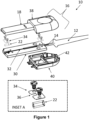
- the device 10 includes an elongate device 12, such as for example a laser catheter, including at least one optical fiber 14 (shown in FIGURE 1 as a bundle of optical fibers) extending through an elongate device 12.
- the laser catheter 12 may also comprise a strain relief portion thereof.
- a coupler (generally shown in FIGURE 1 as element 16 in FIGURE 1 ) is attached to a proximal end of the laser catheter 12.
- the coupler 16 includes a connector 18 configured to mate, or otherwise attached, with an associated light source (not shown in FIGURE 1 ) configured to supply laser light to the optical fibers 14.
- a portion of the bundle of optical fibers 14 is disposed within the connector 18.
- the coupler 16 also includes a holding member 22 secured within the connector 18. As best shown in INSET A of FIGURE 1 , the holding member 22 includes a through hole 24 through which end of the proximal portion of the bundle of optical fibers 14 can be in the through hole 24 of the holding member 22.
- FIGURE 1 also shows that the coupler 16 includes a slide piece 30 configured to mate with the light source.
- the slide piece 30 includes a channel 32 formed therein that is configured to receive and secure the bundle of fibers 14 within the slide piece 30.
- the slide piece 30 is configured to connect with the connector 18 to secure the holding member 22 and the bundle of optical fibers 14 therebetween.
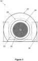
- FIGURE 2 shows an embodiment of the holding member 22.
- the holding member 22 comprises a capillary tube having a light input end 26 arranged to receive light from the light source when the slide piece 30 is mated with the light source, and a flared end 28 opposite the light input end 26.
- the through hole 24 comprises a lumen of the capillary tube 22 having the flared end 28.
- an outer diameter of the flared end 28 of the through hole 24 is larger than a perimeter of the channel 32 of the slide piece 30. This allows the bundle of optical fibers 14 to run from through the through hole 24 to the laser catheter 12 and reducing chances of damage to the optical fibers 14.
- View B of FIGURE 2 shows an opposing view of the holding member 22.
- a bottom portion of the inner diameter of the capillary tube 22 is also aligned with the bottom of the channel 32 of the slide piece 30 to reduce bending that might break or misalign the optical fibers 14 that could cause breakage and to aid in manufacturability. This allows the optical fibers 14 to slide along the channel 32 and right into the tapered end 28 of the through hole 24.
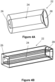
- FIGURES 4A and 4B show different embodiments of the capillary tube 22.
- the through hole 24 has a circular cross-section
- the through hole 24 has a rectangular cross-section.
- FIGURE 4A also shows the tapered end 28 of the through hole 24.
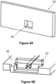
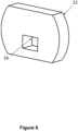
- FIGURES 5A, 5B , and 6 show other embodiments of the holding member 22.
- the holding member 22 comprises a plate 22 including the through hole 24 passing therethrough.
- FIGURE 5B shows the plate 22 positioned within the slide piece 30.
- FIGURE 6 shows the holding member 22 comprising a disk 22 including the through hole 24 passing therethrough.
- the plate/disk 22 can provide more flexibility in fabricating sizes and shapes of the through hole 24 that match the shape and size of the laser beam profile supplied by the light source. There are possible cost reductions with thinner materials that are compatible with various machining methods.
- the plate/disk 22 can be water jet or diamond cut instead of the drawing process that is limited to cylinders.
- the plate/disk 22 shape can also be tailored to the slide piece 30 to enable greater coverage to protect the adjacent components from laser energy.
- the laser catheter apparatus 10 further includes a clamp 34 configured to secure the holding member 22 to the slide piece 30 with the through hole 24 positioned at the end of the channel 32 of the slide piece 30.
- the clamp 34 can be secured to the slide piece 30 (for example, with screws as shown in FIGURE 1 ).
- the clamp 34 can comprise a malleable material, such as for example plastic and/or rubber. The malleable material of the clamp 34 reduces a likelihood of damage to the holding member 22.
- the clamp 34 can be positioned over the capillary tube 22 to prevent motion thereof.
- the clamp 34 can be sized to allow visualization of the capillary tube 22 for a user during assembly of the laser catheter assembly 10.
- the clamp 34 can include notch 36 to enhance visibility during the assembly.
- FIGURE 1 also shows that the connector 18 further includes a first cover piece 38 (i.e., a "top” cover piece as shown in FIGURE 1 ) and a second cover piece 40 (i.e., a "bottom” cover piece as shown in FIGURE 1 ).
- the slide piece 30 is secured between the first cover piece 38 and the second cover piece 40.
- the clamp 34 is secured to the slide piece 30 (i.e., with screws, as shown in FIGURE 1 ).
- the clamp 34 can be secured to the first cover piece 38 or to the second cover piece 40.
- the second cover piece 40 includes a slot 42 configured to receive and secure the laser catheter 12.
- the slot 42 can be included in the first cover piece or in both, the first and second cover pieces.
- the connector 18 and the first side piece 38 or first cover piece can be a single component.
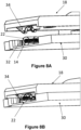
- FIGURES 7 , 8A, and 8B show different embodiments of the clamp 34.
- the clamp 34 is secured to a portion of the first cover piece 38.
- the clamp 34 is configured to apply a compressive force to the capillary tube 22 to hold the capillary tube 22 in place in the channel 32 of the slide piece 30.
- FIGURES 8A and 8B show an embodiment where the clamp 34 comprises a spring configured to engage and hold the capillary tube 22 in place in the channel 32 of the slide piece 30.
- FIGURE 8A shows the clamp 34 prior to engagement with the capillary tube 22, and
- FIGURE 8B shows the clamp 34 engaged with the capillary tube 22.
- FIGURE 9 shows a view of the slide piece 30.
- the slide piece 30 includes the channel 32 for receiving the bundle of optical fibers 14.
- the slide piece 30 can also include a recess 44 configured to receive the holding member 22 (i.e., either the capillary tube 22 or the plate/disk 22).
- the recess 44 can be machined into the slide piece 30 at the desired setback based on the size of the laser catheter 12 and a number of optical fibers 14.
- the laser beam profile becomes larger at larger setbacks, therefore smaller fiber packs have a smaller setback (i.e., closer to the edge of the slide piece 30) and larger fiber packs have a larger setback (farther from the edge of the slide piece 30).
- the recess 44 can have a "dog bone” shape, a V-channel or similar structure that holds the capillary tube 22 in place.
- the recess 44 is machined in a way that allows the capillary tube 22 to align with the channel 32 of the slide piece 30 to be more manufacturable and reduce the risk of fiber breakage.
- the clamp 34 is placed on top of the capillary tube 22.
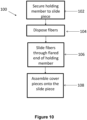
- an illustrative embodiment of a method or process 100 of assembling the laser catheter assembly 10 is diagrammatically shown as a flowchart.
- the holding member 22 is secured to the slide piece 30 so that the through hole 24 of the holding member 22 is aligned with the channel 32 of the slide piece 30.
- the securing operation 102 can comprise clamping the holding member 22 to the slide piece 30 with the clamp 34.
- a proximal portion of the bundle of optical fibers 14 is disposed within the channel 32 of the slide piece 30.
- an end of the proximal portion of the bundle of optical fibers 14 is slid through the flared end 28 of the through hole 24 of the holding member 22 so that the end of the proximal portion of the bundle of optical fibers 14 is compressed into the through hole 24.
- the outer diameter of the flared end 28 of the through hole 24 is larger than a perimeter of the channel 32 of the slide piece 30.
- the flared end 28 guides the end of the proximal portion of the bundle of optical fibers 14 into the through hole 24.
- the first cover piece 38 and the second cover piece 40 are assembled on opposing ends of the slide piece 30 to form the coupler 16.
- the securing operation 102 is performed during the assembling operation 108 by securing the clamp 34 to the first cover piece 38, and the clamp 34 presses the holding member 22 against the slide piece 30 during the assembling operation 108.
- the coupler 16 can be attached to the laser source, and a laser beam can be supplied to the optical fibers 14.
Landscapes
- Health & Medical Sciences (AREA)
- Surgery (AREA)
- Physics & Mathematics (AREA)
- Life Sciences & Earth Sciences (AREA)
- Engineering & Computer Science (AREA)
- Medical Informatics (AREA)
- Nuclear Medicine, Radiotherapy & Molecular Imaging (AREA)
- Electromagnetism (AREA)
- Optics & Photonics (AREA)
- Biomedical Technology (AREA)
- Heart & Thoracic Surgery (AREA)
- Otolaryngology (AREA)
- Molecular Biology (AREA)
- Animal Behavior & Ethology (AREA)
- General Health & Medical Sciences (AREA)
- Public Health (AREA)
- Veterinary Medicine (AREA)
- Laser Surgery Devices (AREA)
Priority Applications (5)
| Application Number | Priority Date | Filing Date | Title |
|---|---|---|---|
| CN202380068847.0A CN120018823A (zh) | 2022-09-29 | 2023-09-20 | 具有毛细管组件的激光导管近侧联接器 |
| PCT/EP2023/075874 WO2024068379A1 (fr) | 2022-09-29 | 2023-09-20 | Coupleur proximal de cathéter laser avec ensemble tube capillaire |
| EP23772881.1A EP4593747A1 (fr) | 2022-09-29 | 2023-09-20 | Coupleur proximal de cathéter laser avec ensemble tube capillaire |
| US19/112,621 US20260083502A1 (en) | 2022-09-29 | 2023-09-20 | Laser catheter proximal coupler with capillary tube assembly |
| JP2025514738A JP2025534957A (ja) | 2022-09-29 | 2023-09-20 | 毛細管アセンブリを備えたレーザカテーテル近位カプラ |
Applications Claiming Priority (1)
| Application Number | Priority Date | Filing Date | Title |
|---|---|---|---|
| US202263411320P | 2022-09-29 | 2022-09-29 |
Publications (1)
| Publication Number | Publication Date |
|---|---|
| EP4344665A1 true EP4344665A1 (fr) | 2024-04-03 |
Family
ID=84246090
Family Applications (1)
| Application Number | Title | Priority Date | Filing Date |
|---|---|---|---|
| EP22205614.5A Withdrawn EP4344665A1 (fr) | 2022-09-29 | 2022-11-04 | Coupleur proximal de catheter laser a ensemble tube capillaire |
Country Status (1)
| Country | Link |
|---|---|
| EP (1) | EP4344665A1 (fr) |
Citations (3)
| Publication number | Priority date | Publication date | Assignee | Title |
|---|---|---|---|---|
| US7050692B2 (en) | 2002-03-29 | 2006-05-23 | The Spectranetics Corporation | Proximal coupler for optical fibers |
| US9678275B1 (en) * | 2016-05-23 | 2017-06-13 | InnovaQuartz LLC | Efficient coupling of infrared radiation to renal calculi |
| CN113341502A (zh) * | 2021-06-30 | 2021-09-03 | 长飞光纤光缆股份有限公司 | 一种基于三维波导的多芯光纤耦合器和制备方法 |
-
2022
- 2022-11-04 EP EP22205614.5A patent/EP4344665A1/fr not_active Withdrawn
Patent Citations (3)
| Publication number | Priority date | Publication date | Assignee | Title |
|---|---|---|---|---|
| US7050692B2 (en) | 2002-03-29 | 2006-05-23 | The Spectranetics Corporation | Proximal coupler for optical fibers |
| US9678275B1 (en) * | 2016-05-23 | 2017-06-13 | InnovaQuartz LLC | Efficient coupling of infrared radiation to renal calculi |
| CN113341502A (zh) * | 2021-06-30 | 2021-09-03 | 长飞光纤光缆股份有限公司 | 一种基于三维波导的多芯光纤耦合器和制备方法 |
Similar Documents
| Publication | Publication Date | Title |
|---|---|---|
| US7470269B2 (en) | Ophthalmic surgery light transmitting apparatus | |
| US9770363B2 (en) | Steerable laser probe | |
| US9519107B2 (en) | Methods and apparatus related to a launch connector portion of a ureteroscope laser-energy-delivery device | |
| US5231684A (en) | Optical fiber microlens | |
| AU2015214381C1 (en) | Manufacturing an articulating ophthalmic surgical probe | |
| US4519390A (en) | Fiber optic laser catheter | |
| US6574401B2 (en) | Optical fiber-handpiece combination for medical laser treatments | |
| US5304172A (en) | Fiber optic probe | |
| US5190028A (en) | Method for manufacturing a disposable arthroscopic probe | |
| WO1985005263A1 (fr) | Sonde de laser medical et chirurgical ii | |
| US9907616B1 (en) | System for TFL lithotripsy, including endoscope with detachable and replaceable wave guide and method for use | |
| JPH06174950A (ja) | 光ファイバの装着具 | |
| US20260083502A1 (en) | Laser catheter proximal coupler with capillary tube assembly | |
| US20050113814A1 (en) | Apparatus and method for limiting the re-use of fiber optic, laser energy delivery devices | |
| RU58904U1 (ru) | Пункционная световодная игла (варианты) и ограничитель для нее | |
| JPH0614936A (ja) | レーザープローブ、ハンドピースおよびこれらを備えた手持ち器具並びに装置 | |
| US20250116820A1 (en) | Hermetically sealed fiber optics with protective window | |
| JPH0475011B2 (fr) | ||
| JP2001061859A (ja) | ハンドピース |
Legal Events
| Date | Code | Title | Description |
|---|---|---|---|
| PUAI | Public reference made under article 153(3) epc to a published international application that has entered the european phase |
Free format text: ORIGINAL CODE: 0009012 |
|
| STAA | Information on the status of an ep patent application or granted ep patent |
Free format text: STATUS: THE APPLICATION HAS BEEN PUBLISHED |
|
| AK | Designated contracting states |
Kind code of ref document: A1 Designated state(s): AL AT BE BG CH CY CZ DE DK EE ES FI FR GB GR HR HU IE IS IT LI LT LU LV MC ME MK MT NL NO PL PT RO RS SE SI SK SM TR |
|
| STAA | Information on the status of an ep patent application or granted ep patent |
Free format text: STATUS: THE APPLICATION IS DEEMED TO BE WITHDRAWN |
|
| 18D | Application deemed to be withdrawn |
Effective date: 20241005 |