EP4344752A1 - Notsauerstoffabgabeanordnung mit sauerstoffspeicherpatrone - Google Patents
Notsauerstoffabgabeanordnung mit sauerstoffspeicherpatrone Download PDFInfo
- Publication number
- EP4344752A1 EP4344752A1 EP23187029.6A EP23187029A EP4344752A1 EP 4344752 A1 EP4344752 A1 EP 4344752A1 EP 23187029 A EP23187029 A EP 23187029A EP 4344752 A1 EP4344752 A1 EP 4344752A1
- Authority
- EP
- European Patent Office
- Prior art keywords
- gas
- adsorbent
- cartridge
- bypass line
- valve
- Prior art date
- Legal status (The legal status is an assumption and is not a legal conclusion. Google has not performed a legal analysis and makes no representation as to the accuracy of the status listed.)
- Granted
Links
Images


Classifications
-
- A—HUMAN NECESSITIES
- A61—MEDICAL OR VETERINARY SCIENCE; HYGIENE
- A61M—DEVICES FOR INTRODUCING MEDIA INTO, OR ONTO, THE BODY; DEVICES FOR TRANSDUCING BODY MEDIA OR FOR TAKING MEDIA FROM THE BODY; DEVICES FOR PRODUCING OR ENDING SLEEP OR STUPOR
- A61M16/00—Devices for influencing the respiratory system of patients by gas treatment, e.g. ventilators; Tracheal tubes
- A61M16/22—Carbon dioxide-absorbing devices ; Other means for removing carbon dioxide
-
- A—HUMAN NECESSITIES
- A62—LIFE-SAVING; FIRE-FIGHTING
- A62B—DEVICES, APPARATUS OR METHODS FOR LIFE-SAVING
- A62B18/00—Breathing masks or helmets, e.g. affording protection against chemical agents or for use at high altitudes or incorporating a pump or compressor for reducing the inhalation effort
- A62B18/08—Component parts for gas-masks or gas-helmets, e.g. windows, straps, speech transmitters, signal-devices
- A62B18/088—Devices for indicating filter saturation
-
- A—HUMAN NECESSITIES
- A62—LIFE-SAVING; FIRE-FIGHTING
- A62B—DEVICES, APPARATUS OR METHODS FOR LIFE-SAVING
- A62B19/00—Cartridges with absorbing substances for respiratory apparatus
-
- A—HUMAN NECESSITIES
- A62—LIFE-SAVING; FIRE-FIGHTING
- A62B—DEVICES, APPARATUS OR METHODS FOR LIFE-SAVING
- A62B21/00—Devices for producing oxygen from chemical substances for respiratory apparatus
-
- A—HUMAN NECESSITIES
- A62—LIFE-SAVING; FIRE-FIGHTING
- A62B—DEVICES, APPARATUS OR METHODS FOR LIFE-SAVING
- A62B7/00—Respiratory apparatus
-
- A—HUMAN NECESSITIES
- A62—LIFE-SAVING; FIRE-FIGHTING
- A62B—DEVICES, APPARATUS OR METHODS FOR LIFE-SAVING
- A62B9/00—Component parts for respiratory or breathing apparatus
- A62B9/006—Indicators or warning devices, e.g. of low pressure, contamination
-
- C—CHEMISTRY; METALLURGY
- C01—INORGANIC CHEMISTRY
- C01B—NON-METALLIC ELEMENTS; COMPOUNDS THEREOF; METALLOIDS OR COMPOUNDS THEREOF NOT COVERED BY SUBCLASS C01C
- C01B13/00—Oxygen; Ozone; Oxides or hydroxides in general
- C01B13/02—Preparation of oxygen
- C01B13/0229—Purification or separation processes
- C01B13/0248—Physical processing only
- C01B13/0259—Physical processing only by adsorption on solids
- C01B13/0262—Physical processing only by adsorption on solids characterised by the adsorbent
- C01B13/027—Zeolites
-
- F—MECHANICAL ENGINEERING; LIGHTING; HEATING; WEAPONS; BLASTING
- F16—ENGINEERING ELEMENTS AND UNITS; GENERAL MEASURES FOR PRODUCING AND MAINTAINING EFFECTIVE FUNCTIONING OF MACHINES OR INSTALLATIONS; THERMAL INSULATION IN GENERAL
- F16K—VALVES; TAPS; COCKS; ACTUATING-FLOATS; DEVICES FOR VENTING OR AERATING
- F16K15/00—Check valves
- F16K15/02—Check valves with guided rigid valve members
- F16K15/025—Check valves with guided rigid valve members the valve being loaded by a spring
-
- F—MECHANICAL ENGINEERING; LIGHTING; HEATING; WEAPONS; BLASTING
- F17—STORING OR DISTRIBUTING GASES OR LIQUIDS
- F17C—VESSELS FOR CONTAINING OR STORING COMPRESSED, LIQUEFIED OR SOLIDIFIED GASES; FIXED-CAPACITY GAS-HOLDERS; FILLING VESSELS WITH, OR DISCHARGING FROM VESSELS, COMPRESSED, LIQUEFIED, OR SOLIDIFIED GASES
- F17C11/00—Use of gas-solvents or gas-sorbents in vessels
-
- A—HUMAN NECESSITIES
- A61—MEDICAL OR VETERINARY SCIENCE; HYGIENE
- A61M—DEVICES FOR INTRODUCING MEDIA INTO, OR ONTO, THE BODY; DEVICES FOR TRANSDUCING BODY MEDIA OR FOR TAKING MEDIA FROM THE BODY; DEVICES FOR PRODUCING OR ENDING SLEEP OR STUPOR
- A61M16/00—Devices for influencing the respiratory system of patients by gas treatment, e.g. ventilators; Tracheal tubes
- A61M16/0057—Pumps therefor
- A61M16/0078—Breathing bags
-
- A—HUMAN NECESSITIES
- A61—MEDICAL OR VETERINARY SCIENCE; HYGIENE
- A61M—DEVICES FOR INTRODUCING MEDIA INTO, OR ONTO, THE BODY; DEVICES FOR TRANSDUCING BODY MEDIA OR FOR TAKING MEDIA FROM THE BODY; DEVICES FOR PRODUCING OR ENDING SLEEP OR STUPOR
- A61M16/00—Devices for influencing the respiratory system of patients by gas treatment, e.g. ventilators; Tracheal tubes
- A61M16/06—Respiratory or anaesthetic masks
-
- A—HUMAN NECESSITIES
- A61—MEDICAL OR VETERINARY SCIENCE; HYGIENE
- A61M—DEVICES FOR INTRODUCING MEDIA INTO, OR ONTO, THE BODY; DEVICES FOR TRANSDUCING BODY MEDIA OR FOR TAKING MEDIA FROM THE BODY; DEVICES FOR PRODUCING OR ENDING SLEEP OR STUPOR
- A61M16/00—Devices for influencing the respiratory system of patients by gas treatment, e.g. ventilators; Tracheal tubes
- A61M16/08—Bellows; Connecting tubes ; Water traps; Patient circuits
- A61M16/0883—Circuit type
- A61M16/0891—Closed circuit, e.g. for anaesthesia
-
- A—HUMAN NECESSITIES
- A61—MEDICAL OR VETERINARY SCIENCE; HYGIENE
- A61M—DEVICES FOR INTRODUCING MEDIA INTO, OR ONTO, THE BODY; DEVICES FOR TRANSDUCING BODY MEDIA OR FOR TAKING MEDIA FROM THE BODY; DEVICES FOR PRODUCING OR ENDING SLEEP OR STUPOR
- A61M16/00—Devices for influencing the respiratory system of patients by gas treatment, e.g. ventilators; Tracheal tubes
- A61M16/10—Preparation of respiratory gases or vapours
- A61M16/1005—Preparation of respiratory gases or vapours with O2 features or with parameter measurement
-
- A—HUMAN NECESSITIES
- A61—MEDICAL OR VETERINARY SCIENCE; HYGIENE
- A61M—DEVICES FOR INTRODUCING MEDIA INTO, OR ONTO, THE BODY; DEVICES FOR TRANSDUCING BODY MEDIA OR FOR TAKING MEDIA FROM THE BODY; DEVICES FOR PRODUCING OR ENDING SLEEP OR STUPOR
- A61M16/00—Devices for influencing the respiratory system of patients by gas treatment, e.g. ventilators; Tracheal tubes
- A61M16/20—Valves specially adapted to medical respiratory devices
- A61M16/201—Controlled valves
-
- A—HUMAN NECESSITIES
- A61—MEDICAL OR VETERINARY SCIENCE; HYGIENE
- A61M—DEVICES FOR INTRODUCING MEDIA INTO, OR ONTO, THE BODY; DEVICES FOR TRANSDUCING BODY MEDIA OR FOR TAKING MEDIA FROM THE BODY; DEVICES FOR PRODUCING OR ENDING SLEEP OR STUPOR
- A61M2202/00—Special media to be introduced, removed or treated
- A61M2202/02—Gases
- A61M2202/0208—Oxygen
-
- A—HUMAN NECESSITIES
- A61—MEDICAL OR VETERINARY SCIENCE; HYGIENE
- A61M—DEVICES FOR INTRODUCING MEDIA INTO, OR ONTO, THE BODY; DEVICES FOR TRANSDUCING BODY MEDIA OR FOR TAKING MEDIA FROM THE BODY; DEVICES FOR PRODUCING OR ENDING SLEEP OR STUPOR
- A61M2205/00—General characteristics of the apparatus
- A61M2205/02—General characteristics of the apparatus characterised by a particular materials
- A61M2205/0227—Materials having sensing or indicating function, e.g. indicating a pressure increase
-
- A—HUMAN NECESSITIES
- A61—MEDICAL OR VETERINARY SCIENCE; HYGIENE
- A61M—DEVICES FOR INTRODUCING MEDIA INTO, OR ONTO, THE BODY; DEVICES FOR TRANSDUCING BODY MEDIA OR FOR TAKING MEDIA FROM THE BODY; DEVICES FOR PRODUCING OR ENDING SLEEP OR STUPOR
- A61M2205/00—General characteristics of the apparatus
- A61M2205/58—Means for facilitating use, e.g. by people with impaired vision
- A61M2205/583—Means for facilitating use, e.g. by people with impaired vision by visual feedback
- A61M2205/584—Means for facilitating use, e.g. by people with impaired vision by visual feedback having a color code
-
- A—HUMAN NECESSITIES
- A61—MEDICAL OR VETERINARY SCIENCE; HYGIENE
- A61M—DEVICES FOR INTRODUCING MEDIA INTO, OR ONTO, THE BODY; DEVICES FOR TRANSDUCING BODY MEDIA OR FOR TAKING MEDIA FROM THE BODY; DEVICES FOR PRODUCING OR ENDING SLEEP OR STUPOR
- A61M2205/00—General characteristics of the apparatus
- A61M2205/75—General characteristics of the apparatus with filters
- A61M2205/7563—General characteristics of the apparatus with filters with means preventing clogging of filters
-
- A—HUMAN NECESSITIES
- A62—LIFE-SAVING; FIRE-FIGHTING
- A62B—DEVICES, APPARATUS OR METHODS FOR LIFE-SAVING
- A62B18/00—Breathing masks or helmets, e.g. affording protection against chemical agents or for use at high altitudes or incorporating a pump or compressor for reducing the inhalation effort
Definitions
- the present invention relates to a portable oxygen storage cartridge allowing a supply of oxygen (O 2 ) to a user, for a sufficient time, in a particular situation generating a harmful, hypoxic and/or atmosphere loaded with deleterious compounds, such as than in the chemical or mining industries, which cartridge further comprising a bypass line containing an adsorbent and a saturation indicator, and emergency oxygen distribution assembly comprising such a cartridge fluidly connected to a gas reservoir and to a respiratory interface, such as a respiratory mask.
- O 2 oxygen
- gaseous O 2 is used to correct a hypoxemic situation, that is to say when the saturation of oxyhemoglobin in the blood is lower than a normal value, for example lower than 90%, in a human person. , whatever their age, ie newborns, children, adolescents, adults, elderly people or others, suffering from a respiratory pathology such as Chronic Obstructive Pulmonary Disease (COPD), Acute Respiratory Distress Syndrome (ARDS) or other.
- COPD Chronic Obstructive Pulmonary Disease
- ARDS Acute Respiratory Distress Syndrome
- medical grade oxygen is provided to the “hypoxic” person either within a hospital or outside a hospital, for example in a mobile emergency unit (SAMU, ambulances, etc.) or at patient's home.
- the oxygen supplied to the patient can come either from a gas pipe (eg hospital network), or from a pressurized gas cylinder containing for example 400 to 1000 L of O 2 (gaseous vol. ) compressed up to 200 bar abs or more (measured at 1 atm).
- a portable oxygen storage cartridge comprising a closed cartridge body defining an internal volume receiving gaseous oxygen.
- the cartridge body is fluidly connected to a gas reservoir and to a respiratory interface, in particular a respiratory mask, such as a nasal or facial mask, so that gas exchanges can take place between these elements.
- Gas flow control valves are used to control gas inlets and outlets from the internal volume.
- the internal volume contains a bed of adsorbent, for example zeolite, used to trap the CO 2 molecules found in the gas exhaled by a user and which enter the internal volume of the cartridge after being recovered by the mask respiratory.
- Such an oxygen storage cartridge is effective in providing an emergency supply of oxygen to a person faced with a particular situation generating a harmful hypoxic atmosphere (ie ⁇ 21% O 2 ) and/or loaded with deleterious compounds, such as smoke in the event of a fire or the like, to allow it to avoid breathing this harmful atmosphere by providing it with oxygen, for a period of several tens of minutes.
- a harmful hypoxic atmosphere ie ⁇ 21% O 2
- deleterious compounds such as smoke in the event of a fire or the like
- the portable oxygen storage cartridge further comprises at least one bypass line connecting fluidly to connection sites located upstream of each of said first and second gas orifices so as to that part of the gas entering the internal volume through one or the other of said first and second gas orifices is diverted and circulates within said at least one bypass line.
- Said at least part of said at at least one bypass line is formed of at least one transparent material and contains at least one second adsorbent material and at least one saturation indicator material.
- part of the gas flow containing CO 2 can be diverted and circulate in the bypass line.
- the CO 2 is then gradually retained on the second adsorbent material, for example soda lime, which causes a variation in the pH.
- This progressive variation in pH can then be “detected” by the saturation indicator material, such as ethyl violet, which will then gradually change color depending on the quantity of CO 2 trapped on the second adsorbent material, therefore its saturation by trapped CO 2 .
- This color variation reflecting the saturation rate of the second adsorbent material can be visualized easily and in real time by the user through the transparent material constituting the bypass line so as to indicate to him when the second adsorbent material is completely saturated and therefore the cartridge is no longer operational and must be replaced.
- the invention further relates to an emergency oxygen distribution assembly comprising a portable oxygen storage cartridge for storing oxygen according to the invention, as described above, fluidly connected via said first and second ports gas from the cartridge to a gas reservoir and to a respiratory interface.
- the gas reservoir has a flexible envelope and/or the respiratory interface is a respiratory mask, in particular a nasal or facial mask.
- Fig. 1 is a schematic sectional view of one embodiment of a cartridge 1 for supplying emergency oxygen, as described by FR2201224 Or FR2201227 .
- the cartridge 1 comprises a cartridge body or main body 13 closed at its two opposite ends 13A, 13B by a first cover 18 and a second cover 19, such as walls or the like closing the two ends 13A, 13B of the main body 13, of so as to delimit an internal volume 12 used for storing gas, namely here oxygen (O 2 ) in gaseous form.
- gas namely here oxygen (O 2 ) in gaseous form.
- first gas orifice 1-1 and a second gas orifice 1-2 which communicate fluidly with the internal volume 12. They are arranged on either side of the main body 13, i.e. say that the first gas orifice 1-1 is arranged in the first cover 18, while the second gas orifice 1-2 is arranged in the second cover 19.
- a first valve 2 and a second flow control valve 3 are arranged in these first gas orifice 1-1 and second gas orifice 1-2, respectively, to control the gas inlets and outlets, that is to say the gas flows passing through the cartridge body 13, as explained below.
- the main body 13 is formed here of an external tubular envelope 11, preferably of cylindrical shape.
- the main body 13 is preferably made of metal, for example an aluminum alloy.
- the tubular envelope 11 is elongated and extends along a main axis XX between the two ends 13A, 13B.
- the first cover 18 and the second cover 19 carrying the gas orifices 1-1, 1-2 take the cylindrical body 13, typically the tubular envelope 11, in a “sandwich” and are fixed there in a sealed manner, for example welded or crimped.
- the first and second covers 18, 19 are preferably also made of metal, for example an aluminum alloy.
- the wall of the peripheral envelope 11 forming the main body 13 is thin, that is to say it has a thickness of the order of a few tenths of a millimeter.
- cartridge 1 is of the order of 300 ml to 900 ml (water equiv.).
- One (or more) bed(s) 14 of one (or more) first particulate adsorbent 14-1 is arranged in the interior volume 12.
- the bed of first adsorbent 14 -1 is sandwiched and held by/between two sieve structures 15, 16, more simply called 'sieves', that is to say that the first sieve 15 and the second sieve 16 are arranged on either side other of the adsorbent bed 14 so as to hold it in position in the internal volume 12 of the cartridge 1.
- the sieve structures 15, 16 which are arranged radially in the internal volume 12, that is to say perpendicular to the main axis XX, and extend over the entire internal section of the main body 13 of shape cylindrical.
- the sieve structures 15, 16 make it possible to separate the internal volume 12 into several internal chambers or compartments, namely a central chamber 124 containing the first bed 14 of first adsorbent 14-1 located in the center of the cartridge 1, and a first and a second gas collection chamber 121, 122 located at opposite ends 13A, 13B, that is to say between the central chamber 124 and the first and second covers 18, 19.
- the sieves 15, 16 are for example formed of a mesh of metal fibers having a multitude of pores whose dimensions are smaller than the dimensions of the first adsorbent 14-1. According to other embodiments, the sieves 15, 16 can be in the form of foams comprising or formed of interconnected cells, or even in the form of grids, for example metal grids, or the like.
- the sieves 15, 16 are dimensioned to retain the adsorbent particles from the first bed 14 of first adsorbent 14-1.
- the bed 14 of first adsorbent 14 is “trapped” and held between the two sieves 15, 16, while the gas molecules are free to circulate through them.
- the first adsorbent 14-1 is chosen to allow gas molecules to be adsorbed, in particular those of oxygen, due to tiny pores on its surface, that is to say pores of the order of or a few nanometers (nm).
- it can be chosen from activated carbons, organometallic structures or MOF for “ Metal Organic Framework ” or zeolites.
- a zeolite adsorbent is preferably used, that is to say one or more zeolites, in the form of particles, such as granules, beads or the like, of one (or more) zeolite having a high adsorption capacity, that is to say at least 3 ml/g at 1 bar and 20°C, for oxygen, for example a 13X or 5A zeolite, for example the zeolite referenced Z10-ZZ marketed by the company Zeochem ® .
- the adsorbent bed 14 does not fill the entire internal volume 12 of the cartridge 1 but is arranged only in the central chamber 124 so that there are empty spaces at the two ends 13A, 13B of the internal volume 12 forming the first 121 and second 122 gas collection chambers.
- the first gas collection chamber 121 is located between the first cover 18 carrying the first gas orifice 1-1 and the first sieve 15, and the second gas collection chamber 122 is located between the second cover 19 carrying the second orifice of gas 1-2 and the second sieve 16.
- the two sieves 15, 16 separate the central chamber 124 containing the first adsorbent bed 14, first and second gas collection chambers 121, 122 which are located on either side of said central chamber 124, that is to say which sandwich it while being separated from it by the sieve 15, 16.
- the gaseous oxygen cartridge 1 has, as already said, also a first valve 2 and a second flow control valve 3 arranged at its two opposite ends 13A, 13B, typically carried by the covers 18, 19 and arranged at the first and second gas ports 1-1, 1-2.
- the first and second flow control valves 2, 3 serve to control the gas circulation, that is to say the gas flows entering and leaving the internal volume 12 of the cartridge 1, via the first and second gas orifices 1-1, 1-2 and through said first and second flow control valves 2, 3, as explained below and illustrated on Fig. 2 to Fig. 8 .
- They are fixed in a sealed manner, for example welded or crimped, to the covers 18, 19, typically they pass through the covers 18, 19.
- the first and second flow control valves 2, 3 are preferably but not necessarily identical.
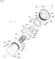
- Fig. 2 is an exploded view of the first valve 2 equipping the oxygen storage cartridge 1 of the invention schematized in Fig. 1 , knowing that the second valve 3 is strictly identical to it and functions in the same way (valve 3 is therefore not detailed below).
- the first valve 2 like the second valve 3, is formed of an assembly of several elements 20-24 cooperating with each other, comprising a valve body 20, an annular sealing means 21, a movable element 22, an elastic means 23, such as a cylindrical spring with turns, and a cover part 24, which are detailed below.
- elements 20-24 are arranged coaxially with respect to each other with respect to the axis XX of the valves 2, 3 and the cartridge 1.
- the elements 20-24 are metallic, for example in an alloy of aluminum; of course, other suitable materials may also be suitable.
- the valve body 20 is of generally cylindrical shape. It has a length of the order of 8 to 16 mm measured between its two ends 20-1, 20-2, and an internal diameter (Di) typically between 18 and 30 mm.
- the peripheral wall 201 of the valve body 20 carries, at its first end 20-1, an annular flange 202 projecting radially outwards.
- annular collar 202 is integral with the cylindrical external peripheral wall 201 of the valve body 20. They can be formed from a single piece or from several pieces assembled together.
- the collar 202 forms an external shoulder, stretching over the entire external periphery or perimeter of the valve body 20, making it possible to ensure a fluid seal between the valve body 20 and the cover 18 integrating the first valve 2 within the first orifice 1-1, for example by being fixed there by crimping, welding or any other suitable technique.
- valve body 20 also internally has an annular bottom 205, preferably flat.
- the annular base 205 has in its center a circular recess 203, and forms an internal shoulder, stretching along the internal wall or internal perimeter of the valve body 20.
- valve body 20 carries a thread 204 fitted on a part 201a of its internal wall 201, from its second end 20-2. This tapping 204 allows the connection by screwing of the support element 24, as explained below.
- the first valve 2 also comprises an annular sealing means 21, namely here a flat annular seal, e.g. an O-ring.
- it has a thickness of approximately 1 mm and an external diameter (De) slightly less than the internal diameter (Di) of the valve body 20, i.e. De ⁇ Di, so that it can be inserted into the valve body 20 and come to position itself on the internal shoulder formed by the annular bottom 205 of the valve body 20.
- the flat annular seal 21 comprises a front face 214 oriented towards the annular bottom 205 of the valve body 20 and a rear face 215 opposite the front face 214, that is to say oriented towards the flange 222 of the valve body 20.
- mobile element 22 as detailed below.
- it also has a central passage 210 whose diameter is greater than that of the circular recess 203 of the valve body 20.
- nitrile rubber also called acrylonitrile butadiene rubber or NBR rubber for “ Nitrile Butadiene Rubber ” in English.
- the mobile element 22 is a structure having a general cup shape. More precisely, the movable element 22 comprises a front portion 221 of cylindrical shape which is open at its distal end 221b and closed, that is to say closed, at its proximal end 221a by a bottom wall 223, for example disc-shaped.
- the bottom wall 223 projects radially outwards, that is to say away from the external peripheral surface of the front portion 221 of cylindrical shape so as to form a collar 222, i.e. a structure in a ring, extending all around the cylindrical proximal end 221a of the front portion 221.
- the cylindrical portion 221 has an external diameter less than the internal diameter of the circular recess 203 of the valve body 20, while the collar 222 has an external diameter greater than that of the recess 203 of the valve body 20 so that the the movable element 22 is movable axially (axis XX) through the circular recess 203 of the valve body 20 and the central recess 210 of the flat annular seal 21 but cannot completely exit it, given that there is retained by the collar 222 when it abuts on the flat annular seal 21, which is itself arranged on the annular bottom 205 of the valve body 20, that is to say sandwiched between the annular bottom 205 of the valve body 20 and the flange 222 of the movable element 22.
- the peripheral wall of the cylindrical front portion 221 is perforated, that is to say it has several lateral openings 227.
- the exterior face 224 of the bottom wall 223 comprises a central boss 225, that is to say a raised element, a surface protrusion or the like, typically of circular section.
- the central boss 225 is general cylindrical shape and has a height of the order of 1 mm and a diameter which is less than the diameter of the collar 222, as visible in Fig. 2 , for example a diameter of the order of 4 to 8 mm.
- the elastic means 23 is a cylindrical coil spring delimiting a cylindrical central passage 231
- the diameter of the central boss 225 is slightly less than that of the central passage 231 of the spring so that the spring can be inserted on the boss central 225 in the manner of a sleeve.
- the central boss 225 cooperates with the elastic means 23, as explained below.
- the elastic means 23 is preferably a cylindrical coil spring positioned around the central boss 225, like a sleeve, and presses on the exterior face 224 of the bottom wall 223 in a substantially annular zone located immediately around the central boss 225 of the movable element 22.
- the elastic means 23, i.e. the spring, comprises a front end 232 coming into contact with the movable element 22 and a rear end 233 coming into contact with the cover part 24.
- the internal diameter of the central passage 231 of the coil spring is therefore slightly greater than the diameter of the central boss 225, as already explained.
- the elastic means 23 elastically pushes the movable element 22 towards the sealing means 21.
- the first valve 2 also comprises a tubular cover piece 24 delimiting an internal housing 240 to accommodate (at least) the elastic means 2 which is compressed and will then push back axially (XX) the movable element 22.
- the cover piece 24 is formed of a main body 241 of cylindrical shape whose wall is pierced, that is to say crossed, by one or more openings or side windows 242.
- the main body 241 comprises, at its front end 24a, an opening 245 which communicates with the internal housing 240.
- the main body is closed by a wall forming a bottom 243, preferably a flat bottom.
- the cover part 24 has the general shape of a cup or the like with side openings 242.
- the main body 241 of the cover part 24 also has, on its exterior surface, on the side of its front end 24a, a peripheral thread 244 which is complementary to the tapping 204 of the valve body 20 so that the cover part 24 can be fitted fix by screwing to said valve body 20 by sandwiching the elastic means 23, the movable element 22 and the sealing means 21, as visible on Fig. 4 .
- the sealing means that is to say the flat seal 21
- the sealing means is inserted into the valve body 20. Its front face 214 comes into contact with the annular bottom 205 which forms an internal shoulder of the valve body 20 .
- the circular recess 203 located in the center of the annular bottom 205 of the valve body 20 is in fluid communication with the central passage 210 of the flat seal 21.
- the cover piece 24 when the cover piece 24 is aimed at the valve body 20, it acts on the elastic means 23, namely the cylindrical coil spring, which is then compressed and then pushes, in turn, the movable element 22 in direction of the valve body 20.
- the movable element 22 then moves axially until its front portion 221 of cylindrical shape passes through the central passage 210 of the flat seal 21 and the circular recess 203 located in the center of the annular bottom 205 of the valve body 20 until it projects out of the valve body 20.
- the translational movement of the movable element 22 is stopped when the collar 222 abuts against the rear face 215 of the flat seal 21.
- the flat seal 21 finds itself “sandwiched” between the flat bottom 205 of the valve body 1 and the flange 222 of the moving part 22 which is pushed back by the cylindrical spring 23.
- the front end 232 of the cylindrical spring 23 comes into contact with the exterior face 224 of the bottom wall 223 of the movable element 22 to push it elastically axially towards the flat seal 21, that is to say towards valve body 1.
- the rear end 233 of the cylindrical spring 23 is in contact with the internal surface of the bottom wall 243 of the cover part 24, preferably it has just been placed around an internal boss 247 projecting from the center of the internal surface of the bottom wall 243 so as to maintain mechanics of the rear end 233 of the cylindrical spring 23, as explained above for the boss 225.
- the spring 23 is therefore held by and between the internal bosses 247 of the cover part 24 and external bosses 225 of the moving part 22.
- housings or recesses such as notches 226, are arranged in the flange 222 of the moving part 22 and axial guides 246, ie guide rails or the like, are arranged axially along the internal wall of the part -cover 24.
- the notches 226 are shaped to accommodate said axial guides 246 so that these axial guides 246 can guide the translational movements of the moving part 22 in the cover part 24.
- the moving part 22 can slide better in the internal volume of the cover part 24, in particular depending on the compression rate of the spring 23.
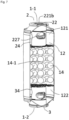
- Fig. 4 is a side view and in section of the valve 2 of Fig. 2 , in its “rest” position, that is to say free from any external constraint.
- the spring 23 is compressed (zone 234) between the flange 222 of the movable part 22 and the bottom of the cover part 24, and the movable part 22 then pushes the flat seal 21 against the flat bottom 205 of the body valve 20 so as to obtain a fluid seal between them.
- Cartridge 1 is then sealed and its internal volume 12 can then store oxygen under pressure.
- the cartridge 1 can be filled with O 2 at a pressure of a few bars, for example of the order of a maximum of 10 absolute bars, which makes it possible to meet logistical constraints, in particular transportation and storage.
- the introduction of the O 2 into the envelope 11 can be done via a filling valve (not shown) arranged for example on the cover 18 or preferably, via one of the valves 2,3, that is to say - say through one or the other of the orifices 1-1, 1-2 which receive the first and second flow control valves 2, 3.
- first adsorbent 14-1 in the internal volume 12 of the cartridge 1 makes it possible to store a quantity of oxygen much greater than that which this gas container 1 could contain in the absence of adsorbent.
- first adsorbent 14-1 a zeolite having a strong oxygen adsorption capacity is used, which therefore makes it possible to very significantly increase the gas storage capacity within the cartridge 1.
- a cartridge 1 of 660 ml of internal volume 12 can contain approximately 400 g of adsorbent 14-1 and, consequently, adsorb approximately 12 L of O 2 , while The interstitial space around the adsorbent particles 14-1 defines an “empty” volume in which O 2 molecules will also be compressed and stored, thus making it possible to increase the total capacity to approximately 15 L of O 2 ( at atmospheric pressure). For comparison, in the absence of 14-1 adsorbent, we could only store around 6 L of O 2 , or 2.5 times less.
- Fig. 5 and Fig. 6 represent a configuration (partially truncated views) where said first valve 2 is in the “actuated” position, that is to say when an external force is applied to the front part 221 of the moving part 22, for example when connection of a connector or the like, as explained below.
- the moving part 22 has undergone an axial translation towards the inside of the cartridge 1, that is to say in the direction of the cover part 24, which has the consequence of compressing the spring 23 towards the bottom of part-cover 24 all by freeing the passage of gas between the flat seal 21 and the flat bottom 205 of the valve body 20.
- the translation of the moving part 22 away from the valve body 20 causes a loss of contact between the front face of the flange 222 and the flat seal 21 and a fluid communication is then created between the exterior and the interior of the cartridge 1, via the first control valve 2, in particular through the side openings 227 of the moving part 22 and the side openings 242 of the cover part 24.
- the second valve 3 operates on the same principle.
- Fig. 7 shows the oxygen storage cartridge 1 with its two control valves 2, 3 in the "actuated" position, the structure and operation of the second control valve 3 being identical to those of the first control valve 2.
- the control valves 2, 3 are in such an "actuated" position, when the oxygen storage cartridge of Fig. 1 has been connected by a user to external devices, for example to, on the one hand, a first gas conduit 4 and, on the other hand, a second gas conduit 6, as illustrated in Fig. 8 , thus forming an emergency oxygen distribution assembly 50, as illustrated in Fig. 9 .
- the first conduit 4 comprises a cylindrical envelope 41 having a hollow internal conduit 42 or lumen, having the shape of a hollow cylinder.
- the first conduit 4 is also fluidly connected to a deformable or flexible reservoir 5 (partially shown on Fig. 8 And Fig. 9 ) empty of gas, at the time of connection to the cartridge 1, but can be filled, ie inflated, with a given volume of gas after connection of the first conduit 4 to the cartridge 1.
- the reservoir 5 can be configured to collect a volume of gas greater than or equal to the volume of gas contained in the interior volume 12 of gas cartridge 1, ie O 2 .
- the reservoir 5 can be formed from a flexible polymer envelope.
- the first conduit 4 is connected fluidically, in a sealed manner, for example to the bottom 19 of the cartridge 1, for example by clipping, screwing or otherwise, carrying the second valve 3.
- the internal conduit 42 of the first conduit 4 will then act on the moving part 22 of the control valve 3 to push it towards the inside of the cartridge 1 so that the second valve 3 finds itself in the “actuated” position, with rupture of the seal at the level of the flat seal of the control valve 3, as explained below.
- the user can connect a second conduit 6 to the valve 2 fitted to the cover 18, which, again, will push back the moving part 22 to move the first valve 2 into its “actuated” position. , as described above, and then establish a fluid connection between the internal conduit of the second conduit 6, the internal volume 12, the internal conduit 42 of the first conduit 4 and then, by extension, the reservoir 5.
- the second conduit 6 can for example supply a respiratory interface 25, such as a respiratory mask, visible in Fig. 9 , which can be nasal or facial (ie naso-buccal), that is to say that the cartridge 1 is then ready for use by the user, who can inhale oxygen coming from the cartridge 1 and /or tank 5.
- a respiratory interface 25 such as a respiratory mask, visible in Fig. 9 , which can be nasal or facial (ie naso-buccal), that is to say that the cartridge 1 is then ready for use by the user, who can inhale oxygen coming from the cartridge 1 and /or tank 5.
- a respiratory interface 25 is chosen, such as a sealed respiratory mask, that is to say comprising sealing means around the perimeter of the opening through which the user breathes, that is to say the rear opening of the mask receiving the nose (nasal mask) or the nose and mouth of the user (face mask), for example sealing means of the flexible cushion type or the like coming into contact with the areas of the face of the user surrounding their nose and/or mouth, in order to create a fluid seal.
- a sealed respiratory mask that is to say comprising sealing means around the perimeter of the opening through which the user breathes, that is to say the rear opening of the mask receiving the nose (nasal mask) or the nose and mouth of the user (face mask), for example sealing means of the flexible cushion type or the like coming into contact with the areas of the face of the user surrounding their nose and/or mouth, in order to create a fluid seal.
- part of the O 2 contained in the flexible reservoir 5 emerges from the latter then passes successively into the internal conduit 42 of the first conduit 4, the interior volume 12 of cartridge 1 to through the adsorbent bed 14 and then emerge from the interior volume 12 via the second conduit 6 and finally reach the respiratory mask 25 worn by the user.
- part of the O 2 inhaled (approx. 5% vol.) has been replaced by CO 2 and the gas exhaled by the user therefore contains CO 2 , water vapor and a high concentration of O 2 , that is to say more than 90% by volume.
- the exhaled gas will follow the opposite path to that followed by the inhaled oxygen, namely take the second conduit 6, pass through the first valve 2 to then reach the interior volume 12 of the cartridge 1, and then pass successively through the bed of adsorbent 14, then the second valve 3 and the first conduit 4 to finally reach the deformable tank 5.
- a characteristic of the chosen adsorbent 14-1 is that its adsorption capacity differs depending on the molecules considered.
- the adsorption capacity of O 2 is relatively low compared to the adsorption capacity of CO 2 or water vapor, typically 50 to 100 times greater.
- the adsorption capacity of a zeolite for example of the Zeochem Z10-ZZ or 5A type, thus presents a storage capacity in volume similar to the total volume of O 2 initially present in gas cartridge 1, measured at 10 bar. This capacity is even greater for water vapor.
- the metabolic oxygen consumption of an individual is a maximum of 0.5 L/min, which implies that after 10 minutes of repeated inhalation/exhalation, tank 5 contains approximately 5L less O 2 , under the aforementioned conditions, namely a pressure of 10 bar and a container volume of 660 ml. This makes it possible to meet the respiratory needs of a user for several tens of minutes.
- adsorbents can be used, for example several successive beds of different adsorbents, namely zeolites or others.
- Such an emergency oxygen distribution assembly 50 comprising a portable oxygen storage cartridge 1 according to the invention connected, on the one hand, to a tank 5 and, on the other hand, to a respiratory interface 25, such a mask, can be used to provide oxygen to a person, for a sufficient time, in a particular situation generating a harmful, hypoxic and/or atmosphere loaded with deleterious compounds.
- the reservoir 5 and the respiratory interface 25 are mechanically connected to the oxygen storage cartridge 1 while ensuring fluid continuity between them, via suitable connection means, such as for example male/female interlocking connections, for example screwed or bayonet system, or other.
- suitable connection means such as for example male/female interlocking connections, for example screwed or bayonet system, or other.
- such an emergency oxygen distribution assembly 50 does not make it easy to assess the saturation level of the adsorbent 14-1, capturing the CO 2 contained in the gas exhaled by the user, during his repeated expiratory phases. Indeed, as time goes by and the expiratory phases follow one another, the quantity of CO 2 retained by the first adsorbent, typically zeolite particles, gradually increases, that is to say that the CO 2 s 'accumulates little by little in the first bed of adsorbent 14.
- this quantity of CO 2 could exceed the adsorption capacity of said first adsorbent 14-1 and in fact all or part of the exhaled CO 2 could circulate through the second valve 3, the first conduit 4 to finally reach the deformable reservoir 5 and accumulate there, leading to a significant risk of poisoning and/or hypoxia for the user.
- the cartridge body 13 of the O 2 1 storage cartridge which is typically formed of a tubular envelope 11, typically of cylindrical shape, is generally made of metal, for example an aluminum alloy , and the same applies to the first 18 and second 19 covers which take the cylindrical body 13 in a “sandwich” and are fixed there in a sealed manner, the entire cartridge 1 is then opaque, therefore preventing any visualization of the adsorbent 14 by the user.
- the first adsorbent 14-1 which is particles of zeolite or the like, does not undergo any visually perceptible modification, that is to say in shape, texture and/or color, when it gradually becomes saturated with CO 2 , and could therefore not allow the user to determine visually its saturation level.
- the invention proposes an improved O 2 1 storage cartridge whose architecture and operation are generally identical to those of Fig. 1 to Fig. 9 , that is to say as described above, but implementing a bypass line 71, the architecture, role and operation of which are described below. Common or identical elements are not repeated since already detailed above; just refer to it.
- the O 2 1 storage cartridge is equipped with a bypass line 71, also called a diversion line, such as an elongated tube, connecting fluidly to connection sites 42, 62 located upstream of the first and second gas ports 1-1; 1-2, that is to say whose ends are connected to the path of the gas, outside the cartridge 1, so that part of the gas, typically the gas rich in CO 2 exhaled by the user, entering the internal volume 12 of the cartridge 1, through one or the other of the first and second gas orifices 1-1; 1-2, is derived and circulates within this bypass line 71.
- a bypass line 71 also called a diversion line, such as an elongated tube, connecting fluidly to connection sites 42, 62 located upstream of the first and second gas ports 1-1; 1-2, that is to say whose ends are connected to the path of the gas, outside the cartridge 1, so that part of the gas, typically the gas rich in CO 2 exhaled by the user, entering the internal volume 12 of the cartridge 1, through one or the other of the first and second
- part of the gas circulating between the respiratory interface 25, cartridge 1 and the reservoir 5 (cf. Fig. 11 ), is derived and bypasses the O 2 storage cartridge 1 by circulating within this bypass line 71 and no longer within the cartridge 1.
- the bypass line 71 preferably connects to connection sites 42, 62 located between the cartridge 1 and, on the one hand, the gas tank 5 and, on the other hand, the respiratory interface 25 of the emergency oxygen distribution assembly 50 according to the invention, that is to say sites located upstream of the first and second gas orifices 1-1; 1-2, therefore on either side of cartridge 1.
- bypass line 71 contains at least one second adsorbent material 75 and at least one saturation indicator material, preferably mixed with each other.
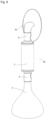
- Fig. 10 which is similar to the Fig. 7 , with the exception of the additional bypass line 71, represents the cartridge 1 according to the invention with its two control valves 2, 3 in the "actuated" position, after connection of the first conduit 4 to a deformable reservoir 5 and the second conduit 6 to a respiratory interface 25, such as a nasal or facial mask, as illustrated in Fig. 12 .
- the first conduit 4 comprises a first branch conduit 43 which is fluidly connected to it at a first connection site 42 so that the lumen 41 of the first conduit 4 is in fluid communication with the lumen 44 of the first branch conduit 43.
- the second conduit 6 comprises a second branch conduit 63 which is fluidly connected to it at a second connection site 62 so that the lumen 61 of the second conduit 6 is in fluid communication with the lumen 64 of the second conduit 6. derivation 63.
- the first and second diversion conduits 43, 63 are respectively connected fluidly, by clipping or any other means, to the two opposite ends 72, 73 of the bypass line 71, namely here a long thin tube, also called a diversion tube, formed of one (or more) transparent material, such as a thermoplastic, for example polycarbonate.
- the internal volume 74 of said diversion tube 71 is filled with a second adsorbent 75, as described below.
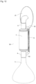
- the emergency oxygen distribution assembly 50 of the present invention is shown in simplified form in Fig. 11 . It is understood that there exists a fluidic relationship between the internal conduit or lumen 61 of the second conduit 6, the volume internal 12 of the O 2 1 storage cartridge, the internal conduit or lumen 41 of the first conduit 4, and the flexible reservoir 5 so that the gas can circulate between these elements of the reservoir 5 to the mask 25 connected to the second leads 6, and vice versa.
- the second conduit 6 has a branch (at 62) extended by the second branch conduit 63 which communicates fluidly with a second end 73 of the bypass line 71 and, similarly, the first conduit 4 has a branch (at 42) extended by the first branch conduit 43 which communicates fluidly with a first end 72 of the bypass line 71.
- the bypass line 71 includes the second adsorbent 75 which is held there between two sieves 76, 77 which sandwich it.
- the sieves 77 of the bypass line 71 may be similar or identical to the first and second sieves 15 and 16 arranged in the cartridge body 11, so as to allow gas circulation while preventing the second adsorbent 75 from moving in the bypass line 71.
- first and second conduits 4, 6 There is a fluidic relationship between the first and second conduits 4, 6 and the first and second diversion conduits 43, 63 so that a portion of the gas exhaled by the user can take the bypass line 71 by passing through the two sieves 76, 77 and the second adsorbent bed 75 sandwiched between them.
- part of the O 2 contained in the flexible reservoir 5 comes out of the latter then passes into the upstream portion 42a of the first conduit 4 to then be distributed between the portion downstream 42b of said conduit 4 and the first branch conduit 43 of the first conduit 4.
- a majority quantity of gas (ie > 80% of the volume) circulating in the downstream portion 42b of the first conduit 4 can then penetrate into the interior volume 12 of the cartridge 1, pass through the first bed of adsorbent 14, before exiting of the interior volume 12 via the upstream portion 62a of the second conduit 62.
- a minority quantity of gas (ie ⁇ 20% of the volume) circulating in the first diversion conduit 43 passes through the adsorbent 75 contained in the line of bypass 71, ie elongated transparent tube, takes the second branch conduit 63 of the second conduit 6 to finally emerge, at the level of the branch 62, in the downstream portion 62b of the second conduit 6.
- the gas flow circulating in the downstream portion 62b of the second conduit 6 is therefore the sum of the gas flows coming from the cartridge 1 and the bypass line 71.
- This gas flow then travels through the lumen of the second conduit 6 to then arrive at the respiratory interface 25, like a respiratory mask worn by the user.
- the exhaled gas will follow the opposite path from the respiratory interface 25 to the reservoir 5 through the cartridge 1, on the one hand, and the bypass line 71, ie elongated transparent tube, on the other hand.
- This exhaled gas contains CO 2 , water vapor and a high concentration of O 2 , typically more than 90% by volume, since some of the inhaled O 2 (approx. 5% vol. ) has been substituted by CO 2 in the user's lungs.
- the gas ultimately reaches tank 5 where it resides until the following inhalation phase.
- the bypass gas path i.e. -say the quantity of second adsorbent 75, the dimensioning of the bypass conduits 63, 43 and the bypass line 71 in order to determine the exact quantity of gas passing through the bypass gas path. For example, we can ensure that 10% of the gas passes in the bypass gas path and therefore 90% in the main gas path, or any other proportion.
- first adsorbent 14 contained in the oxygen storage cartridge 1 is of the zeolite type, for example the zeolite referenced Z10-ZZ marketed by the company Zeochem ®
- second adsorbent 75 contained in the bypass line 71 soda lime (ie composed mainly of calcium hydroxide), preferably a mixture containing (at least) calcium hydroxide (CaOH) 2 and ethyl violet as colored indicator.
- adsorbent/colored indicator mixture is marketed under the name Litholyme TM by the company Allied Healthcare Product Inc.
- This adsorbent/colored indicator mixture is in the form of granules mainly comprising calcium hydroxide (CaOH ) 2 , ie > 95% by weight approximately, lithium chloride (LiCl), ie ⁇ 3% by weight approximately, and approximately 1% by weight of ethyl violet.
- the calcium hydroxide (CaOH) 2 in the adsorbent/colored indicator mixture reacts only with the CO 2 contained in the gas exhaled by the user to form calcium carbonate CaCOs.
- the chemical reaction is irreversible and induces a change in the pH to which the colored indicator of the “ethyl violet” type or the like is sensitive and then turns from a whitish color, such as an off-white, to a violet color, such as a bright purple. This modification then makes it possible to visualize the state of each granule of soda lime.
- the colored indicator changes color depending on the pH to which it is subjected.
- the CO 2 adsorption capacity of this type of granule is of the order of 130 ml of CO 2 per g of product, ie 130 ml/g.
- the first adsorbent 14 has a capacity of 65 ml/g, or half as much.
- the CO 2 present in the part of the gas flow circulating in the bypass line 71 will be captured by the second adsorbent 75, in particular its upstream portion 75a located downstream of the second sieve 77 until said portion 75a becomes saturated and the saturation “front” moves to the downstream portion 75b upstream of the first sieve 76.
- the second adsorbent 15 is then at complete saturation and can no longer adsorb CO 2 .
- second adsorbent 75 depends on the diversion rate “x”, but that this mass also itself influences the diversion rate “x” because it causes resistance to flow.
- the progression of the saturation fronts in the adsorbents 14, 75 occurs in a ratiometric manner.
- the saturation level 0% when the first adsorbent 14 captures the CO 2 near the first sieve 15 and similarly, when the second adsorbent 75 captures the CO 2 near its second screen 77, and 100% when the first adsorbent 14 captures the CO 2 around the second screen 16 and therefore the second adsorbent 75 captures the CO 2 around its first screen 76.
- the second adsorbent 75 follows the same saturation level as the first adsorbent 14 as the user successively exhales, with the advantage of providing the user with visual information of the level of progression of the front. adsorption, marked by the progressive appearance of a purple color of the second adsorbent 75.
- the emergency oxygen distribution assembly 50 with O2 storage cartridge 1 provided with a visual indicator makes it possible to measure in real time the saturation rate of the first adsorbent 14 contained in the storage cartridge of O2 1 and anticipate its replacement before the CO 2 is no longer adsorbed and gradually fills tank 5.
Landscapes
- Health & Medical Sciences (AREA)
- General Health & Medical Sciences (AREA)
- Pulmonology (AREA)
- Engineering & Computer Science (AREA)
- Emergency Management (AREA)
- Business, Economics & Management (AREA)
- Chemical & Material Sciences (AREA)
- General Engineering & Computer Science (AREA)
- Life Sciences & Earth Sciences (AREA)
- Emergency Medicine (AREA)
- Organic Chemistry (AREA)
- Mechanical Engineering (AREA)
- General Life Sciences & Earth Sciences (AREA)
- Hematology (AREA)
- Geology (AREA)
- Inorganic Chemistry (AREA)
- Anesthesiology (AREA)
- Biomedical Technology (AREA)
- Heart & Thoracic Surgery (AREA)
- Analytical Chemistry (AREA)
- Animal Behavior & Ethology (AREA)
- Public Health (AREA)
- Veterinary Medicine (AREA)
- Separation Of Gases By Adsorption (AREA)
- Respiratory Apparatuses And Protective Means (AREA)
- Packages (AREA)
Applications Claiming Priority (1)
| Application Number | Priority Date | Filing Date | Title |
|---|---|---|---|
| FR2209855A FR3139993B1 (fr) | 2022-09-28 | 2022-09-28 | Ensemble de distribution d’oxygène de secours incluant une cartouche de stockage d’oxygène |
Publications (2)
| Publication Number | Publication Date |
|---|---|
| EP4344752A1 true EP4344752A1 (de) | 2024-04-03 |
| EP4344752B1 EP4344752B1 (de) | 2025-06-25 |
Family
ID=85570006
Family Applications (1)
| Application Number | Title | Priority Date | Filing Date |
|---|---|---|---|
| EP23187029.6A Active EP4344752B1 (de) | 2022-09-28 | 2023-07-21 | Notsauerstoffabgabeanordnung mit sauerstoffspeicherpatrone |
Country Status (3)
| Country | Link |
|---|---|
| EP (1) | EP4344752B1 (de) |
| ES (1) | ES3036949T3 (de) |
| FR (1) | FR3139993B1 (de) |
Cited By (1)
| Publication number | Priority date | Publication date | Assignee | Title |
|---|---|---|---|---|
| RU236942U1 (ru) * | 2024-12-17 | 2025-09-01 | Акционерное общество "Росхимзащита" | Поглотительный патрон с устройством контроля состояния химического поглотителя |
Citations (7)
| Publication number | Priority date | Publication date | Assignee | Title |
|---|---|---|---|---|
| FR2201224A1 (de) | 1972-09-29 | 1974-04-26 | Blau Kg Kraftfahrzeugtech | |
| FR2201227A1 (de) | 1972-10-02 | 1974-04-26 | Stevens Peter | |
| WO1995012432A1 (en) * | 1993-11-05 | 1995-05-11 | Purecab Australia Pty. Ltd. | Respiratory filter indicator |
| US7875100B2 (en) * | 2007-08-30 | 2011-01-25 | The Boeing Company | Service life indicator for chemical filters |
| WO2012018766A2 (en) * | 2010-08-06 | 2012-02-09 | Scott Technologies, Inc. | Method and apparatus for integrating chemical and environmental sensors into an air purification filter through a reusable sensor post |
| US20210121649A1 (en) * | 2018-07-17 | 2021-04-29 | Mirola Ip Ab | Portable rebreathing system with staged addition of oxygen enrichment |
| WO2022108320A1 (ko) * | 2020-11-19 | 2022-05-27 | 김명숙 | 호흡을 이용한 산소발생 모듈 및 그 제조방법 |
-
2022
- 2022-09-28 FR FR2209855A patent/FR3139993B1/fr active Active
-
2023
- 2023-07-21 EP EP23187029.6A patent/EP4344752B1/de active Active
- 2023-07-21 ES ES23187029T patent/ES3036949T3/es active Active
Patent Citations (7)
| Publication number | Priority date | Publication date | Assignee | Title |
|---|---|---|---|---|
| FR2201224A1 (de) | 1972-09-29 | 1974-04-26 | Blau Kg Kraftfahrzeugtech | |
| FR2201227A1 (de) | 1972-10-02 | 1974-04-26 | Stevens Peter | |
| WO1995012432A1 (en) * | 1993-11-05 | 1995-05-11 | Purecab Australia Pty. Ltd. | Respiratory filter indicator |
| US7875100B2 (en) * | 2007-08-30 | 2011-01-25 | The Boeing Company | Service life indicator for chemical filters |
| WO2012018766A2 (en) * | 2010-08-06 | 2012-02-09 | Scott Technologies, Inc. | Method and apparatus for integrating chemical and environmental sensors into an air purification filter through a reusable sensor post |
| US20210121649A1 (en) * | 2018-07-17 | 2021-04-29 | Mirola Ip Ab | Portable rebreathing system with staged addition of oxygen enrichment |
| WO2022108320A1 (ko) * | 2020-11-19 | 2022-05-27 | 김명숙 | 호흡을 이용한 산소발생 모듈 및 그 제조방법 |
Cited By (1)
| Publication number | Priority date | Publication date | Assignee | Title |
|---|---|---|---|---|
| RU236942U1 (ru) * | 2024-12-17 | 2025-09-01 | Акционерное общество "Росхимзащита" | Поглотительный патрон с устройством контроля состояния химического поглотителя |
Also Published As
| Publication number | Publication date |
|---|---|
| FR3139993B1 (fr) | 2024-09-20 |
| FR3139993A1 (fr) | 2024-03-29 |
| ES3036949T3 (en) | 2025-09-26 |
| EP4344752B1 (de) | 2025-06-25 |
Similar Documents
| Publication | Publication Date | Title |
|---|---|---|
| FR2611344A1 (fr) | Appareil respiratoire a circuit ferme | |
| US4781184A (en) | Closed circuit breathing apparatus and method of using same | |
| EP4227575B1 (de) | Tragbare notsauerstoffabgabeanordnung mit sauerstoffspeicherpatrone | |
| AU712110B2 (en) | Oxygen respirator | |
| FR2641975A1 (fr) | Appareil respiratoire a fonctionnement en circulation avec surpression | |
| FR2531341A1 (fr) | Appareil respiratoire protecteur convenant au fonctionnement sous une surpression | |
| FR2946264A1 (fr) | Separateur d'eau a fonction de protection amelioree | |
| WO1990000421A1 (fr) | Appareil respiratoire autonome de secours | |
| US20060225734A1 (en) | Filter for oxygen delivery systems | |
| EP4227574B1 (de) | Tragbare notsauerstoffabgabeanordnung mit flusskontrollventilen | |
| EP4344752B1 (de) | Notsauerstoffabgabeanordnung mit sauerstoffspeicherpatrone | |
| FR2587297A1 (fr) | Systeme de respiration pour scaphandrier | |
| FR2619722A1 (fr) | Appareil respiratoire | |
| EP3848076B1 (de) | Gasversorgungsanordnung mit einem gasbehälter | |
| EP4295881B1 (de) | Anlage zur sauerstoffversorgung eines patienten mit einem elektrochemischen trennmodul mit keramischer membran | |
| EP4108282A1 (de) | Gasversorgungsanlage, die für die behandlung einer person geeignet ist, die einen hohen sauerstoffdurchsatz benötigt | |
| WO2021198738A1 (fr) | Recycleur | |
| WO2009095605A2 (fr) | Récipient mobile de traitement in situ de gaz anesthésiques expirés par un patient | |
| FR2526166A1 (fr) | Dispositif respiratoire muni d'un indicateur d'humidite irreversible | |
| KR102081642B1 (ko) | 급기펌프를 이용한 비상 마스크 | |
| WO2009095611A2 (fr) | Cartouche légère et compact de traitement de gaz anesthésiques expirés par un patient | |
| EP4609937A1 (de) | Anlage zur regenerierung und füllung einer sauerstoffkartusche | |
| FR2844205A1 (fr) | Un dispositif pour un detendeur utilise en plongee (ou d'autres activites similaires) l'embout buccal est a multifonction et permet de recycler le gaz expire par le plongeur | |
| EP4585243A1 (de) | Atemgasversorgungsanlage mit geschlossenem kreislauf und einem permeationsmodul | |
| FR3110436A1 (fr) | Dispositif d’assistance à la respiration |
Legal Events
| Date | Code | Title | Description |
|---|---|---|---|
| PUAI | Public reference made under article 153(3) epc to a published international application that has entered the european phase |
Free format text: ORIGINAL CODE: 0009012 |
|
| STAA | Information on the status of an ep patent application or granted ep patent |
Free format text: STATUS: THE APPLICATION HAS BEEN PUBLISHED |
|
| AK | Designated contracting states |
Kind code of ref document: A1 Designated state(s): AL AT BE BG CH CY CZ DE DK EE ES FI FR GB GR HR HU IE IS IT LI LT LU LV MC ME MK MT NL NO PL PT RO RS SE SI SK SM TR |
|
| STAA | Information on the status of an ep patent application or granted ep patent |
Free format text: STATUS: REQUEST FOR EXAMINATION WAS MADE |
|
| 17P | Request for examination filed |
Effective date: 20241004 |
|
| RBV | Designated contracting states (corrected) |
Designated state(s): AL AT BE BG CH CY CZ DE DK EE ES FI FR GB GR HR HU IE IS IT LI LT LU LV MC ME MK MT NL NO PL PT RO RS SE SI SK SM TR |
|
| GRAP | Despatch of communication of intention to grant a patent |
Free format text: ORIGINAL CODE: EPIDOSNIGR1 |
|
| STAA | Information on the status of an ep patent application or granted ep patent |
Free format text: STATUS: GRANT OF PATENT IS INTENDED |
|
| INTG | Intention to grant announced |
Effective date: 20250224 |
|
| GRAS | Grant fee paid |
Free format text: ORIGINAL CODE: EPIDOSNIGR3 |
|
| GRAA | (expected) grant |
Free format text: ORIGINAL CODE: 0009210 |
|
| STAA | Information on the status of an ep patent application or granted ep patent |
Free format text: STATUS: THE PATENT HAS BEEN GRANTED |
|
| AK | Designated contracting states |
Kind code of ref document: B1 Designated state(s): AL AT BE BG CH CY CZ DE DK EE ES FI FR GB GR HR HU IE IS IT LI LT LU LV MC ME MK MT NL NO PL PT RO RS SE SI SK SM TR |
|
| REG | Reference to a national code |
Ref country code: GB Ref legal event code: FG4D Free format text: NOT ENGLISH |
|
| REG | Reference to a national code |
Ref country code: CH Ref legal event code: EP |
|
| REG | Reference to a national code |
Ref country code: DE Ref legal event code: R096 Ref document number: 602023004245 Country of ref document: DE |
|
| REG | Reference to a national code |
Ref country code: CH Ref legal event code: EP |
|
| REG | Reference to a national code |
Ref country code: IE Ref legal event code: FG4D Free format text: LANGUAGE OF EP DOCUMENT: FRENCH |
|
| REG | Reference to a national code |
Ref country code: ES Ref legal event code: FG2A Ref document number: 3036949 Country of ref document: ES Kind code of ref document: T3 Effective date: 20250926 |
|
| PG25 | Lapsed in a contracting state [announced via postgrant information from national office to epo] |
Ref country code: FI Free format text: LAPSE BECAUSE OF FAILURE TO SUBMIT A TRANSLATION OF THE DESCRIPTION OR TO PAY THE FEE WITHIN THE PRESCRIBED TIME-LIMIT Effective date: 20250625 |
|
| PGFP | Annual fee paid to national office [announced via postgrant information from national office to epo] |
Ref country code: ES Payment date: 20250828 Year of fee payment: 3 |
|
| PGFP | Annual fee paid to national office [announced via postgrant information from national office to epo] |
Ref country code: DE Payment date: 20250722 Year of fee payment: 3 |
|
| REG | Reference to a national code |
Ref country code: LT Ref legal event code: MG9D |
|
| PG25 | Lapsed in a contracting state [announced via postgrant information from national office to epo] |
Ref country code: NO Free format text: LAPSE BECAUSE OF FAILURE TO SUBMIT A TRANSLATION OF THE DESCRIPTION OR TO PAY THE FEE WITHIN THE PRESCRIBED TIME-LIMIT Effective date: 20250925 Ref country code: GR Free format text: LAPSE BECAUSE OF FAILURE TO SUBMIT A TRANSLATION OF THE DESCRIPTION OR TO PAY THE FEE WITHIN THE PRESCRIBED TIME-LIMIT Effective date: 20250926 |
|
| PGFP | Annual fee paid to national office [announced via postgrant information from national office to epo] |
Ref country code: IT Payment date: 20250731 Year of fee payment: 3 |
|
| PG25 | Lapsed in a contracting state [announced via postgrant information from national office to epo] |
Ref country code: BG Free format text: LAPSE BECAUSE OF FAILURE TO SUBMIT A TRANSLATION OF THE DESCRIPTION OR TO PAY THE FEE WITHIN THE PRESCRIBED TIME-LIMIT Effective date: 20250625 |
|
| PG25 | Lapsed in a contracting state [announced via postgrant information from national office to epo] |
Ref country code: HR Free format text: LAPSE BECAUSE OF FAILURE TO SUBMIT A TRANSLATION OF THE DESCRIPTION OR TO PAY THE FEE WITHIN THE PRESCRIBED TIME-LIMIT Effective date: 20250625 |
|
| PGFP | Annual fee paid to national office [announced via postgrant information from national office to epo] |
Ref country code: AT Payment date: 20251020 Year of fee payment: 3 Ref country code: FR Payment date: 20250828 Year of fee payment: 3 |
|
| PG25 | Lapsed in a contracting state [announced via postgrant information from national office to epo] |
Ref country code: RS Free format text: LAPSE BECAUSE OF FAILURE TO SUBMIT A TRANSLATION OF THE DESCRIPTION OR TO PAY THE FEE WITHIN THE PRESCRIBED TIME-LIMIT Effective date: 20250925 |
|
| PG25 | Lapsed in a contracting state [announced via postgrant information from national office to epo] |
Ref country code: LV Free format text: LAPSE BECAUSE OF FAILURE TO SUBMIT A TRANSLATION OF THE DESCRIPTION OR TO PAY THE FEE WITHIN THE PRESCRIBED TIME-LIMIT Effective date: 20250625 |
|
| REG | Reference to a national code |
Ref country code: NL Ref legal event code: MP Effective date: 20250625 |
|
| PG25 | Lapsed in a contracting state [announced via postgrant information from national office to epo] |
Ref country code: NL Free format text: LAPSE BECAUSE OF FAILURE TO SUBMIT A TRANSLATION OF THE DESCRIPTION OR TO PAY THE FEE WITHIN THE PRESCRIBED TIME-LIMIT Effective date: 20250625 |
|
| PG25 | Lapsed in a contracting state [announced via postgrant information from national office to epo] |
Ref country code: PT Free format text: LAPSE BECAUSE OF FAILURE TO SUBMIT A TRANSLATION OF THE DESCRIPTION OR TO PAY THE FEE WITHIN THE PRESCRIBED TIME-LIMIT Effective date: 20251027 |
|
| REG | Reference to a national code |
Ref country code: AT Ref legal event code: MK05 Ref document number: 1805878 Country of ref document: AT Kind code of ref document: T Effective date: 20250625 |
|
| PG25 | Lapsed in a contracting state [announced via postgrant information from national office to epo] |
Ref country code: IS Free format text: LAPSE BECAUSE OF FAILURE TO SUBMIT A TRANSLATION OF THE DESCRIPTION OR TO PAY THE FEE WITHIN THE PRESCRIBED TIME-LIMIT Effective date: 20251025 |
|
| PG25 | Lapsed in a contracting state [announced via postgrant information from national office to epo] |
Ref country code: AT Free format text: LAPSE BECAUSE OF FAILURE TO SUBMIT A TRANSLATION OF THE DESCRIPTION OR TO PAY THE FEE WITHIN THE PRESCRIBED TIME-LIMIT Effective date: 20250625 Ref country code: SM Free format text: LAPSE BECAUSE OF FAILURE TO SUBMIT A TRANSLATION OF THE DESCRIPTION OR TO PAY THE FEE WITHIN THE PRESCRIBED TIME-LIMIT Effective date: 20250625 |
|
| PG25 | Lapsed in a contracting state [announced via postgrant information from national office to epo] |
Ref country code: CZ Free format text: LAPSE BECAUSE OF FAILURE TO SUBMIT A TRANSLATION OF THE DESCRIPTION OR TO PAY THE FEE WITHIN THE PRESCRIBED TIME-LIMIT Effective date: 20250625 |
|
| PG25 | Lapsed in a contracting state [announced via postgrant information from national office to epo] |
Ref country code: PL Free format text: LAPSE BECAUSE OF FAILURE TO SUBMIT A TRANSLATION OF THE DESCRIPTION OR TO PAY THE FEE WITHIN THE PRESCRIBED TIME-LIMIT Effective date: 20250625 |
|
| PG25 | Lapsed in a contracting state [announced via postgrant information from national office to epo] |
Ref country code: EE Free format text: LAPSE BECAUSE OF FAILURE TO SUBMIT A TRANSLATION OF THE DESCRIPTION OR TO PAY THE FEE WITHIN THE PRESCRIBED TIME-LIMIT Effective date: 20250625 |
|
| PG25 | Lapsed in a contracting state [announced via postgrant information from national office to epo] |
Ref country code: SK Free format text: LAPSE BECAUSE OF FAILURE TO SUBMIT A TRANSLATION OF THE DESCRIPTION OR TO PAY THE FEE WITHIN THE PRESCRIBED TIME-LIMIT Effective date: 20250625 |
|
| PG25 | Lapsed in a contracting state [announced via postgrant information from national office to epo] |
Ref country code: RO Free format text: LAPSE BECAUSE OF FAILURE TO SUBMIT A TRANSLATION OF THE DESCRIPTION OR TO PAY THE FEE WITHIN THE PRESCRIBED TIME-LIMIT Effective date: 20250625 Ref country code: LU Free format text: LAPSE BECAUSE OF NON-PAYMENT OF DUE FEES Effective date: 20250721 |
|
| REG | Reference to a national code |
Ref country code: BE Ref legal event code: MM Effective date: 20250731 |
|
| PG25 | Lapsed in a contracting state [announced via postgrant information from national office to epo] |
Ref country code: MC Free format text: LAPSE BECAUSE OF FAILURE TO SUBMIT A TRANSLATION OF THE DESCRIPTION OR TO PAY THE FEE WITHIN THE PRESCRIBED TIME-LIMIT Effective date: 20250625 |
|
| PG25 | Lapsed in a contracting state [announced via postgrant information from national office to epo] |
Ref country code: DK Free format text: LAPSE BECAUSE OF FAILURE TO SUBMIT A TRANSLATION OF THE DESCRIPTION OR TO PAY THE FEE WITHIN THE PRESCRIBED TIME-LIMIT Effective date: 20250625 |
|
| PG25 | Lapsed in a contracting state [announced via postgrant information from national office to epo] |
Ref country code: BE Free format text: LAPSE BECAUSE OF NON-PAYMENT OF DUE FEES Effective date: 20250731 |