EP4344778A2 - Walzenmühle und verfahren zum betrieb einer walzenmühle - Google Patents
Walzenmühle und verfahren zum betrieb einer walzenmühle Download PDFInfo
- Publication number
- EP4344778A2 EP4344778A2 EP23196056.8A EP23196056A EP4344778A2 EP 4344778 A2 EP4344778 A2 EP 4344778A2 EP 23196056 A EP23196056 A EP 23196056A EP 4344778 A2 EP4344778 A2 EP 4344778A2
- Authority
- EP
- European Patent Office
- Prior art keywords
- roller
- rotating speed
- feeding rate
- feeding device
- gap
- Prior art date
- Legal status (The legal status is an assumption and is not a legal conclusion. Google has not performed a legal analysis and makes no representation as to the accuracy of the status listed.)
- Pending
Links
- 238000000034 method Methods 0.000 title claims description 23
- 239000002994 raw material Substances 0.000 claims abstract description 60
- 230000005540 biological transmission Effects 0.000 claims abstract description 50
- 230000007246 mechanism Effects 0.000 claims abstract description 18
- 230000003247 decreasing effect Effects 0.000 claims description 21
- 235000013339 cereals Nutrition 0.000 claims description 11
- 239000012530 fluid Substances 0.000 claims description 11
- 230000008859 change Effects 0.000 claims description 8
- 235000010469 Glycine max Nutrition 0.000 claims description 4
- 240000004713 Pisum sativum Species 0.000 claims description 4
- 235000010582 Pisum sativum Nutrition 0.000 claims description 4
- 240000008042 Zea mays Species 0.000 claims description 4
- 235000005824 Zea mays ssp. parviglumis Nutrition 0.000 claims description 4
- 235000002017 Zea mays subsp mays Nutrition 0.000 claims description 4
- 235000005822 corn Nutrition 0.000 claims description 4
- 235000021374 legumes Nutrition 0.000 claims description 4
- 244000068988 Glycine max Species 0.000 claims description 2
- 239000004464 cereal grain Substances 0.000 claims description 2
- 230000007423 decrease Effects 0.000 description 7
- 230000000694 effects Effects 0.000 description 5
- 238000000227 grinding Methods 0.000 description 5
- 235000010627 Phaseolus vulgaris Nutrition 0.000 description 4
- 244000046052 Phaseolus vulgaris Species 0.000 description 4
- 238000000605 extraction Methods 0.000 description 4
- 238000004519 manufacturing process Methods 0.000 description 4
- 241000196324 Embryophyta Species 0.000 description 3
- 241001465754 Metazoa Species 0.000 description 2
- 230000008901 benefit Effects 0.000 description 2
- 238000004049 embossing Methods 0.000 description 2
- 239000000463 material Substances 0.000 description 2
- 239000003755 preservative agent Substances 0.000 description 2
- 230000002335 preservative effect Effects 0.000 description 2
- 238000005299 abrasion Methods 0.000 description 1
- 230000015556 catabolic process Effects 0.000 description 1
- 238000002485 combustion reaction Methods 0.000 description 1
- 239000004020 conductor Substances 0.000 description 1
- 230000008878 coupling Effects 0.000 description 1
- 238000010168 coupling process Methods 0.000 description 1
- 238000005859 coupling reaction Methods 0.000 description 1
- 230000001419 dependent effect Effects 0.000 description 1
- 230000029087 digestion Effects 0.000 description 1
- 239000000446 fuel Substances 0.000 description 1
- 239000008187 granular material Substances 0.000 description 1
- 235000016709 nutrition Nutrition 0.000 description 1
- 238000011017 operating method Methods 0.000 description 1
- 230000003287 optical effect Effects 0.000 description 1
- 230000001737 promoting effect Effects 0.000 description 1
- 230000008439 repair process Effects 0.000 description 1
- 239000011435 rock Substances 0.000 description 1
- 230000035939 shock Effects 0.000 description 1
- 238000003860 storage Methods 0.000 description 1
- 230000001360 synchronised effect Effects 0.000 description 1
Images

Classifications
-
- B—PERFORMING OPERATIONS; TRANSPORTING
- B02—CRUSHING, PULVERISING, OR DISINTEGRATING; PREPARATORY TREATMENT OF GRAIN FOR MILLING
- B02C—CRUSHING, PULVERISING, OR DISINTEGRATING IN GENERAL; MILLING GRAIN
- B02C4/00—Crushing or disintegrating by roller mills
- B02C4/02—Crushing or disintegrating by roller mills with two or more rollers
- B02C4/06—Crushing or disintegrating by roller mills with two or more rollers specially adapted for milling grain
-
- B—PERFORMING OPERATIONS; TRANSPORTING
- B02—CRUSHING, PULVERISING, OR DISINTEGRATING; PREPARATORY TREATMENT OF GRAIN FOR MILLING
- B02C—CRUSHING, PULVERISING, OR DISINTEGRATING IN GENERAL; MILLING GRAIN
- B02C11/00—Other auxiliary devices or accessories specially adapted for grain mills
-
- B—PERFORMING OPERATIONS; TRANSPORTING
- B02—CRUSHING, PULVERISING, OR DISINTEGRATING; PREPARATORY TREATMENT OF GRAIN FOR MILLING
- B02C—CRUSHING, PULVERISING, OR DISINTEGRATING IN GENERAL; MILLING GRAIN
- B02C11/00—Other auxiliary devices or accessories specially adapted for grain mills
- B02C11/04—Feeding devices
-
- B—PERFORMING OPERATIONS; TRANSPORTING
- B02—CRUSHING, PULVERISING, OR DISINTEGRATING; PREPARATORY TREATMENT OF GRAIN FOR MILLING
- B02C—CRUSHING, PULVERISING, OR DISINTEGRATING IN GENERAL; MILLING GRAIN
- B02C4/00—Crushing or disintegrating by roller mills
- B02C4/28—Details
- B02C4/32—Adjusting, applying pressure to, or controlling the distance between, milling members
- B02C4/38—Adjusting, applying pressure to, or controlling the distance between, milling members in grain mills
-
- B—PERFORMING OPERATIONS; TRANSPORTING
- B02—CRUSHING, PULVERISING, OR DISINTEGRATING; PREPARATORY TREATMENT OF GRAIN FOR MILLING
- B02C—CRUSHING, PULVERISING, OR DISINTEGRATING IN GENERAL; MILLING GRAIN
- B02C4/00—Crushing or disintegrating by roller mills
- B02C4/28—Details
- B02C4/42—Driving mechanisms; Roller speed control
-
- B—PERFORMING OPERATIONS; TRANSPORTING
- B02—CRUSHING, PULVERISING, OR DISINTEGRATING; PREPARATORY TREATMENT OF GRAIN FOR MILLING
- B02C—CRUSHING, PULVERISING, OR DISINTEGRATING IN GENERAL; MILLING GRAIN
- B02C4/00—Crushing or disintegrating by roller mills
- B02C4/28—Details
- B02C4/32—Adjusting, applying pressure to, or controlling the distance between, milling members
Definitions
- the invention relates to a roller mill for crushing and/or flattening feed raw material, which roller mill has a frame, at least one roller pair, which comprises a first roller and a second roller, which first and second roller are parallel, so that there is a gap between them, adjustment means for changing the distance between the first roller and second roller, a power transmission mechanism for transmitting the rotational movement of the first roller to the second roller with a desired transmission ratio, a transmission axle in the end of the first roller for connecting to a power engine, an feeding device for feeding feed raw material into the gap between the first roller and the second roller, and a control unit for controlling the operation of said adjustment means and feeding device.
- the invention also relates to a method of operating a roller mill.
- Feed to be used for feeding production animals is manufactured e.g. from various cereal plants, corn, soy, peas and other legumes.
- the feed is manufactured by crushing the grains or beans of the feed plants and adding a preservative among the generated crush.
- the grains or beans can be crushed as dried or fresh.
- the nutritional content of feed manufactured from fresh-crushed grains and beans is higher than that of feed manufactured from dry matters. Additionally, the manufacturing of such feed is less expensive, because the feed raw material does not have to be dried.
- Crushing of feed plant grains or beans is usually done with a roller mill, which has two parallel rollers rotated with a motor.
- the rollers can have a cylindrical shape or they can be made up of discs of varying thickness, set adjacently on the same axle.
- the rollers are connected together with a power transmission mechanism, so that the rotation of the first roller causes the second roller to rotate in an opposite direction to the first roller.
- Power transmission is usually implemented with gear wheels or belt transmission.
- the motor rotating the rollers can belong to the roller mill or the roller mill can be connected via an axle to an external power engine, such as a tractor.
- the granular raw material of the feed is led to pass through the gap between the rollers, whereby they are crushed or at least flattened, so that the surface structure of the grains is broken.
- One of the rollers of the roller pair is made to be moveable in the horizontal direction, so that the width of the gap between the rollers can be changed in accordance with the grain size of the feed raw material presently to be crushed.
- the rotating speed of the second roller is generally adjusted to be lower than the rotating speed of the first roller, whereby a grinding effect improving the crushing and/or flattening is achieved in the narrowest point between the rollers.
- the outer surface of the rollers can have embossing, which promotes passing of the granular material into the gap between the rollers.
- Document EP 0514953 A2 describes a roller mill, which has a first and a second roller, between which there is a gap, into which material to be crushed is led. The width of the gap can be altered by moving the second roller.
- the first roller is rotated with a motor and the rotational movement is transmitted to the second roller with a power transmission mechanism combining the ends of the rollers.
- the power transmission mechanism comprises a freewheel clutch, which enables the second roller to rotate with a higher rotating speed than the transmission ratio.
- the roller mill described in the document is intended especially for crushing rock material.
- the power engine rotating the roller mill such as the tractor or electric motor, is set to rotate at a constant rotating speed, which is as optimal as possible both for the economical use of the power engine and the operation of the roller mill.
- the amount of feed raw material to be fed into the gap increases or its quality changes, whereby more power is needed for rotating the rollers.
- An increased power requirement usually leads to a decrease in the rotating speed of the power engine.
- the increased power requirement of the power engine often leads to increased fuel costs and a decrease in the rotational speed is seen as lowered production of the roller mill.
- An object of the invention is to provide a roller mill and a method of operating a roller mill, with which problems related to prior art can be reduced.
- the objects of the invention are obtained with a roller mill and a method, which are characterised in what is presented in the independent claims. Some advantageous embodiments of the invention are presented in the dependent claims.
- the invention relates to a roller mill for crushing and/or flattening feed raw material, which roller mill has a frame, at least one roller pair, which comprises a first roller and a second roller, which first and second roller are parallel, so that there is a gap between them, adjustment means for changing the distance between the first roller and second roller, a power mechanism for transmitting the rotational movement of the first roller to the second roller with a desired transmission ratio, a transmission axle in the end of the first roller for connecting to a power engine, an feeding device for feeding feed raw material into the gap between the first roller and the second roller, and a control unit for controlling the operation of said adjustment means and feeding device.
- the roller mill additionally comprises a tachometer for measuring the rotating speed of the transmission axle, which tachometer is connected to the control unit, and the control unit is arranged to control the operation of the adjustment means and/or feeding device based on the measured rotating speed.
- said first tachometer is arranged to measure the rotating speed of said first roller.
- said adjustment means comprise an adjustment cylinder for moving the second roller and a pressure gauge for measuring the pressure of the hydraulic fluid in the adjustment cylinder, and said control unit is arranged to change the pressure of the hydraulic fluid in the adjustment cylinder in order to change the width of the gap between the first roller and second roller.
- said feeding device comprises at least one paddle wheel rotated with a motor, and said control unit is arranged to change the rotating speed of the paddle wheel in order to adjust the feeding rate of the feed raw material.
- Still another advantageous embodiment of the roller mill according to the invention comprises a level sensor for measuring the amount of feed raw material accruing on the gap between the roller pair.
- roller mill according to the invention additionally comprises a second tachometer for measuring the rotating speed of the second roller, and said control unit is arranged to move the second roller and/or change the feeding rate of the feeding device in order to adjust the rotating speed of the second roller.
- said rollers have a cylindrical shape or they comprise discs installed adjacently around an axle, the side surfaces of which discs substantially have the shape of a cut cone.
- the method further comprises
- One advantageous embodiment of the method according to the invention comprises, when the measured rotating speeds have exceeded the target rotating speed,
- Still another advantageous embodiment of the method according to the invention comprises, when the measured feed raw material has fallen below the set limit value,
- Still another advantageous embodiment of the method according to the invention comprises, when the difference in the rotating speeds has exceeded the target value,
- fresh, undried granular raw material is used at the feed raw material, such as cereal grains, corn grains, soy beans, peas or other legumes.
- An advantage of the invention is that with its aid, the load of the power engine rotating the roller mill can be optimized, so that its operation is as economical as possible and stresses the power engine as little as possible. This generates savings in the use, service and repair costs for the power engine.
- An advantage of the invention is additionally that with its aid, clogging of the raw material feeding device and outages due to cloggings and device breakdowns can be reduced. Thus, the operation efficiency of the roller mill can be improved.
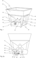
- FIG. 1 shows as an example a roller mill according to the invention seen diagonally from the front and above.
- the roller mill has a frame 10, which comprises four substantially vertical pillars 30 and a substantially square-shaped support ring 32 formed of horizontal beams.
- the pillars are at their upper ends attached to the corners of the support ring.
- the support ring and pillars support a silo 34.
- the silo is a funnel-shaped structural part open at its top side, which has an upper part 35 shaped like a cut pyramid above the support ring, and a lower part 36 below the support ring, placed within the circuit delimited by the pillars.
- the lower part of the silo also has the shape of a cut cone and its downward-pointing tip is connected to the feeding device 40.
- a crushing unit which is placed inside a casing 38 which can be opened.
- the feeding device feeds feed raw material in the silo to be crushed and/or flattened along input channels 42 to the roller pair of the crushing unit inside the casing in a way described below.
- the driving force of the roller pair is produced with a power engine, such as a tractor, outside the roller mill,.
- the roller mill has a transmission axle 18, the end of which extends outside the first end of the casing.
- Figure 2a shows the roller mill of figure 1 seen from the side, from the direction of the first end.
- the section covering the first end wall of the casing has been removed in the figure, to better bring out the structure of the inner part of the casing.
- the roller mill shown in the figure has a roller pair formed from a first roller 12 and a second roller 14.
- the figure shows the first ends of the axles of the first roller 12 and the second roller 14 and the bearing housings surrounding them.
- the first roller is mounted on bearings at both ends with stationary first bearing housings 44 to the frame of the crushing unit.
- the first end of the axle of the first roller 12 extends outside the end wall of the casing and there are grooves, so-called spoors, in the longitudinal direction of the axle on its outer surface,.
- This axle functions as a transmission axle 18, which is connected with an intermediary axle to the power engine, advantageously to a tractor, rotating the first roller,.
- the transmission axle shown in the figure can also be in both ends of the first roller, which enables connecting of the transmission axles of two subsequently placed roller mills with a connecting axle, whereby the connected roller mills can be used simultaneously with one power engine.
- the second bearing housing 48 surrounding the end of the axle of the second roller 14 seen in the figure is an eccentric bearing housing, which is attached in a mobile manner to the frame of the crushing unit.
- the roller mill has adjustment means, which comprise an adjustment axle 50 below the second bearing housing, which adjustment axle can be rotated with a suitable adjustment tool.
- the rotating of it causes the first end of the second roller 14 to move in relation to the first roller.
- the same kind of turning mechanism for the bearing housing of the second roller is also in the second end of the second roller, and these turning mechanisms are connected together with a chain transmission 56, due to which the second bearing housings in both ends of the second rollers always rotate in a synchronized manner.
- an adjustment cylinder 58 belonging to the adjustment means, the cylinder part of which is attached to the frame of the crushing unit, and the shaft of the piston protruding out of the cylinder is connected to the support structures of the second bearing housing.
- the hydraulic fluid pressure in the adjustment cylinder keeps the first and second roller at a standard distance from each other during operation of the roller mill.
- the hydraulics line, which is not shown in the figure, of the adjustment cylinder has a so-called pressure accumulator, which receives pressure shocks and enables a temporary increase in the width of the gap between the first and second roller.
- the second bearing housing can be moved toward the first bearing housing or away from it during operation of the roller mill by adjusting the pressure of the hydraulic fluid inside the adjustment cylinder, whereby the width of the gap between the first and second roller changes ( figure 2c ).
- the pressure of the hydraulic fluid inside the adjustment cylinder is measured with a pressure gauge 59 in connection with the control unit and adjusted with the control unit 22 belonging to the roller mill ( figure 3 ).
- the adjustment means additionally comprise a wedge piece, not shown in the figure, between the first and second bearing housing, and possibly further a clearance strip, which is used for adjusting the minimum distance between the bearing housings, which minimum distance determines the width of the gap between the first and second roller.
- a wedge piece not shown in the figure
- the attachment of the ends of the first and second roller shown in figure 2a is prior art as such, which is not described further in this context.
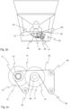
- Figure 2b shows the roller mill of figure 1 seen from the side, from the direction of the second end.
- Figure 2b thus shows the roller mill according to the invention from the opposite end to figure 2a .
- the section covering the second end wall of the casing has been removed in the figure, to better bring out the structure of the inner part of the casing.
- the figure shows the second ends of the axles of the first roller 12 and the second roller 14 and the bearing housings surrounding the ends.
- the second ends of the roller axles are supported on the frame of the crushing unit in the same way as their first ends.
- In the second end of the rollers there is additionally a transmission mechanism, by means of which the rotational movement of the first roller 12 of the roller pair is transmitted to the second roller 14 of the roller pair.
- the rotating speed of the first roller is measured with the first tachometer 24 and the rotating speed of the second roller is measured with the second tachometer 28.
- Both tachometers are connected to the control unit 22 of the roller mill with conductors not shown in the figure
- the transmission mechanism comprises a first control wheel 60, a second control wheel 62 and a tension wheel 64, as well as a belt 66, which circles around said control wheels, tension wheel and a first pulley wheel in the end of the axle of the first roller and a second pulley wheel in the end of the axle of the second roller, in the manner shown in figure 2b .
- the belt is a V-belt and the pulley wheels have a groove, in which the V-belt is fitted.
- the support structure of the tension wheel by means of which the tension wheel is attached in a moveable manner to the crushing unit, comprises a spring member, which pulls the tension wheel away from the second control wheel by spring force. Due to the spring member and the moveable tension wheel, the belt of the transmission mechanism always stays at a suitable tension, even if it stretches during use.
- Figure 2c shows the transmission mechanism of the roller mill shown in figure 2b as a principle view.
- a first pulley wheel 68 Around the end of the axle of the first roller 12 there is a first pulley wheel 68 and around the end of the axle of the second roller 14 there is a second pulley wheel 70.
- the belt 66 circles the first and second pulley wheel, the first and second control wheel 60, 62 and the tension wheel 64 in the manner shown in the figure, whereby the rotational movement of the first roller 12 rotated with the transmission axle is transmitted to the second roller 14, so that the first and second roller rotate in opposite directions.
- the rotational direction of the rollers shown in figure 2c are selected so that the first roller rotates counterclockwise and the second roller rotates clockwise.
- the rollers shown in figure 2 are so-called disc rollers, which comprise a group of discs 15 fitted adjacently around an axle. Both side surfaces of the discs have the shape of a cut cone, so that the thickness of the disc decreases when moving from the axle toward the edge of the disc.
- the side surfaces of the discs may have embossing, such as grooving, promoting passing into the roller gap, flattening or abrasion of the feed raw material.
- the disc rollers are set adjacently, so that the outer edges of the discs of the first roller settle in the groove between the discs of the second roller. A zigzag-shaped gap 16 thus remains between the rollers.
- the ratio between the outer diameters of the first and second pulley wheels determines the transmission ratio of the transmission mechanism.
- the diameter of the first pulley wheel is smaller than the outer diameter of the second pulley wheel, so the rotating speed of the second roller is lower than the rotating speed of the first roller.
- the magnitude of the difference in the rotating speeds can be selected.
- the diameters of the pulley wheels can be selected so that the rotating speed of the second roller is 5-50 %, advantageously 20 %, more advantageously 10 % lower than the rotating speed of the first roller.
- the first pulley wheel is attached to the axle in a fixed manner, so that it always rotates at the same rotating speed as the first roller.
- a freewheel clutch 72 Between the axle of the second roller 14 and the pulley wheel there is a freewheel clutch 72, which allows the pulley wheel to rotate freely around the axle in the opposite direction to the rotational direction of the first roller, but prevents the second pulley wheel from rotating around the axle in the rotational direction of the first roller.
- the second roller thus always rotates in the opposite direction to the first roller, and the rotating speed of the second roller is at least as high as the rotating speed determined based on the transmission ratio of the transmission mechanism.
- the feed raw material to be crushed or flattened being fed between the first and second roller forms such a high friction between the rollers that the rotational movement of the first roller is through the friction transmitted to the second roller more efficiently than with the transmission mechanism.
- the rotating speed of the second roller can rise higher than the rotating speed determined based on the transmission ratio.
- the freewheel clutch can, if necessary, be locked into a position, where it prevents the pulley wheel from rotating freely in both rotational directions.
- the locking of the freewheel clutch can be used when it is desired to maximize the grinding effect achieved with different rotating speeds with the roller mill.
- FIG 3 shows the roller mill shown in figures 1 and 2a-2c as a cross-sectional view.
- the first and second roller 12, 14 seen in the figures are so-called disc rollers, the outer surface of which has parallel V-shaped grooves.
- the disc rollers settle adjacently so that the outer edges of the discs of the first rollers settle in the groove between the discs of the second roller and a zigzag-shaped gap 16 is formed between the rollers.
- the rollers must however not be disc rollers, but the invention can be implemented also in such roller mills, where the outer surface of the rollers has a cylindrical shape. In this kind of mills, the gap between the rollers has a straight shape.
- an feeding device 40 which comprises a compartment 75 opening in the lower part of the silo, inside which compartment there are two paddle wheels 76 rotated with motors not shown in the figure.
- the rotating speeds of the paddle wheels are adjusted with the control unit 22, which is used to control the operation of the motors rotating the paddle wheels.
- Two input channels 42 diverge from the bottom of the compartment, the ends of which channels open up above the gap 16 between the roller pair.
- guide plates 78 which guide the feed raw material coming along the input channels precisely into the gap 16 between the first and second roller.
- the wall of the input channel has a level sensor 26, which measures the amount of feed raw material possibly accruing on the first and second roller.
- the level sensor is advantageously an optical sensor, which is able to measure the amount of accrued feed raw material with the aid of a light beam.
- the extraction chamber 80 Beneath the first and second roller there is an extraction chamber 80, into which the crushed or flattened feed raw material, which has passed through the gap in the roller pairs, falls.
- the extraction chamber has two scrapers 82, which are used for detaching feed raw material which has stuck to the surface of the first and second roller.
- the feed raw material exits the extraction chamber though an opening in its wall (the opening is not shown in the figures).
- the roller mill according to the invention is used for crushing or flattening granular feed raw material.
- the device is suited especially for flattening fresh feed raw material, but it can also be used for crushing dry feed raw material.
- the feed raw material can for example be grain, corn, soy, peas or other legumes.
- a target width is selected for the width of the gap between the rollers of the roller pair based on the grain size of the feed raw material to be processed, and the gap between the first roller and the second roller, i.e. the roller clearance, is adjusted to the target width.
- the adjustment is done by moving the second roller with the adjustment means belonging to the roller mill.
- a target rotating speed is set for the transmission axle of the roller mill, at which speed the power engine and roller mill operate economically and efficiently, and a target feeding rate is set for the feeding device of the roller mill, at which speed feed raw material is fed into the gap between the rollers of the roller pair.
- the rotating speed of the transmission axis 18 connected to the first roller is measured with the first tachometer and the measured rotating speed is compared to the target rotating speed. If the measured rotating speed falls below the target rotating speed, it is a sign that the power engine is overloaded.
- the control unit of the roller mill reacts to this by decreasing the pressure of the hydraulic fluid in the adjustment cylinder, whereby the second roller moves and the width of the gap 16 between the rollers of the roller pair increases to be larger than the target width. Increasing the width of the gap quickly lightens the load of the power engine, whereby the rotating speed of the transmission axle quickly rises. Simultaneously with the increasing of the width of the gap, the feeding rate of the feeding device is lowered to a decreased feeding rate. The decreased feeding rate is clearly lower than the target feeding rate, advantageously 50-80 % of the target feeding rate.
- the width of the gap 16 between the rollers 12, 14 of the roller pair is returned back to the target width by raising the pressure of the hydraulic fluid in the adjustment cylinder.
- a corrected rotating speed is set for the feeding device 40, which speed is lower than the target feeding rate and higher than the decreased feeding rate.
- the feeding rate of the feeding device is gradually increased toward the corrected feeding rate.
- the control unit of the roller mill repeats these procedures for so long that a maximum feeding rate is found for the feeding device, at which speed the power engine can rotate the transmission axle of the roller mill at the target rotating speed.
- the amount of feed raw material accruing on the rollers can be monitored and reacted to, if the amount of accrued feed raw material grows too large.
- a limit value is set for the amount of feed raw material possibly accruing above the gap between the rollers of the roller pair, the amount of feed raw material accruing above the gap between the rollers of the roller pair is measured with the level sensor belonging to the roller mill, and the feeding rate of the feeding device is lowered to the decreased feeding rate, if the measured amount of the feed raw material exceeds the set limit value. As a result of lowering the feeding rate, the amount of feed raw material accrued on the rollers begins to decrease.
- a corrected rotating speed is set for the feeding device, which speed is lower than the target feeding rate and higher than the decreased feeding rate, and the feeding rate of the feeding device is raised gradually from the decreased feeding rate toward the corrected feeding rate.
- the control unit can be programmed to repeat this procedure program so long that the amount of feed raw material accruing on the rollers remains below the set limit value.
- the control unit measures the rotating speed of the second roller with the second tachometer.
- the measured rotating speed of the second roller is compared to the computational rotating speed of the second roller, which is determined based on the rotating speed of the first roller and the transmission ratio of the power transmission mechanism. If the rotating speed of the second roller rises higher than the computational rotating speed, this is a sign that large friction forces act between the roller pair. The increase in the rotating speed of the second roller leads to decreasing of the grinding effect between the rollers.
- the operating method of the roller mill comprises setting a target value for the difference in the rotating speeds of the first roller and second roller, measuring the rotating speeds of the first roller and second roller during operation of the roller mill, calculating the difference between the rotating speeds of the first roller and second roller, and lowering the feeding rate of the feeding device to a decreased feeding rate, if the difference in the rotating speeds is smaller than the target value.
- the amount of feed raw material being fed between the first and the second roller decreases, the friction between the rollers decreases and the rotating speed of the second roller decreases.
- a corrected rotating speed is set for the feeding device, which speed is lower than the target feeding rate and higher than the decreased feeding rate, and the feeding rate of the feeding device is gradually raised toward the corrected feeding rate.
- the control unit of the roller mill can thus be programmed to optimize the feeding rate of the feed raw material, so that a maximum grinding effect of the feed raw material is achieved. Optimizing the grinding effect can affect the storage life properties of the feed raw material, the amount of preservative needed and the function of the digestion of the production animals eating the feed.
Landscapes
- Engineering & Computer Science (AREA)
- Food Science & Technology (AREA)
- Crushing And Grinding (AREA)
Applications Claiming Priority (1)
| Application Number | Priority Date | Filing Date | Title |
|---|---|---|---|
| FI20225849A FI131249B1 (fi) | 2022-09-28 | 2022-09-28 | Valssimylly ja valssimyllyn käyttömenetelmä |
Publications (2)
| Publication Number | Publication Date |
|---|---|
| EP4344778A2 true EP4344778A2 (de) | 2024-04-03 |
| EP4344778A3 EP4344778A3 (de) | 2024-05-15 |
Family
ID=88510859
Family Applications (1)
| Application Number | Title | Priority Date | Filing Date |
|---|---|---|---|
| EP23196056.8A Pending EP4344778A3 (de) | 2022-09-28 | 2023-09-07 | Walzenmühle und verfahren zum betrieb einer walzenmühle |
Country Status (2)
| Country | Link |
|---|---|
| EP (1) | EP4344778A3 (de) |
| FI (1) | FI131249B1 (de) |
Cited By (1)
| Publication number | Priority date | Publication date | Assignee | Title |
|---|---|---|---|---|
| CN119771550A (zh) * | 2025-01-08 | 2025-04-08 | 浙江交投矿业有限公司 | 一种辊式破碎机 |
Citations (2)
| Publication number | Priority date | Publication date | Assignee | Title |
|---|---|---|---|---|
| EP0514953A2 (de) | 1987-04-28 | 1992-11-25 | Nittetsu Mining Co., Ltd. | Walzenbrecher und Brechverfahren mit Anwendung desselben |
| GB2347065B (en) | 1999-02-25 | 2002-10-09 | Aimo Kortteen Konepaja Oy | Roller mill arrangement |
Family Cites Families (5)
| Publication number | Priority date | Publication date | Assignee | Title |
|---|---|---|---|---|
| US5823452A (en) * | 1997-05-05 | 1998-10-20 | Ballew; Russell | Flaker mill |
| FI9055U1 (fi) * | 2010-08-23 | 2011-01-27 | Aimo Kortteen Konepaja Oy | Kiekkovalssimylly |
| CN104353515A (zh) * | 2014-11-27 | 2015-02-18 | 甘肃农业大学 | 小型实验用小麦磨粉机 |
| EP3906116A4 (de) * | 2019-01-05 | 2022-10-19 | Comre IP Pty Ltd. | Vorrichtung, system und verfahren zur kommunikation |
| CN214916719U (zh) * | 2020-12-22 | 2021-11-30 | 山东益本天肽健康产业有限公司 | 一种五谷食品生产用粉碎装置 |
-
2022
- 2022-09-28 FI FI20225849A patent/FI131249B1/fi active
-
2023
- 2023-09-07 EP EP23196056.8A patent/EP4344778A3/de active Pending
Patent Citations (2)
| Publication number | Priority date | Publication date | Assignee | Title |
|---|---|---|---|---|
| EP0514953A2 (de) | 1987-04-28 | 1992-11-25 | Nittetsu Mining Co., Ltd. | Walzenbrecher und Brechverfahren mit Anwendung desselben |
| GB2347065B (en) | 1999-02-25 | 2002-10-09 | Aimo Kortteen Konepaja Oy | Roller mill arrangement |
Cited By (1)
| Publication number | Priority date | Publication date | Assignee | Title |
|---|---|---|---|---|
| CN119771550A (zh) * | 2025-01-08 | 2025-04-08 | 浙江交投矿业有限公司 | 一种辊式破碎机 |
Also Published As
| Publication number | Publication date |
|---|---|
| EP4344778A3 (de) | 2024-05-15 |
| FI131249B1 (fi) | 2025-01-08 |
| FI20225849A1 (fi) | 2024-03-29 |
Similar Documents
| Publication | Publication Date | Title |
|---|---|---|
| AU604324B2 (en) | Roll crusher and method of crushing using the same | |
| EP2155394B1 (de) | Brecher, verfahren zum brechen von material und verfahren zur steuerung eines brechers | |
| EP4344778A2 (de) | Walzenmühle und verfahren zum betrieb einer walzenmühle | |
| US9682524B2 (en) | Pelletizing or granulating apparatus | |
| US6213418B1 (en) | Variable throw eccentric cone crusher and method for operating the same | |
| EP2252401B1 (de) | Taumelhubeinstellvorrichtung für kegelbrecher | |
| CN114011508B (zh) | 用于碾磨设备的辊组件、碾磨设备和方法 | |
| EP2701899B1 (de) | Pelletiermaschine mit einem zuführsystem und verfahren zur herstellung von pelletiertem material | |
| US5072887A (en) | Roll mill | |
| EP3866978B1 (de) | Mühle zum mahlen von materialien mit unterschiedlicher härte und korngrösse | |
| KR20180091075A (ko) | 엔진 연료 소비 제어부를 구비한 수평 분쇄기 | |
| EP4342585A1 (de) | Walzenmühle und verfahren zum betrieb einer walzenmühle | |
| CA1159427A (en) | Flour mill | |
| CN104540592B (zh) | 立式辊磨机中研磨物料的粉碎方法 | |
| JPH0889828A (ja) | ミル用減速機及びこの減速機を備えたミル | |
| US4498856A (en) | Compacting mill | |
| JP3193870B2 (ja) | 破砕装置 | |
| WO1991002644A1 (en) | Pelleting press | |
| US5792485A (en) | Pelleting press | |
| JP3706041B2 (ja) | 竪型ミル | |
| JP3576455B2 (ja) | 竪型ミル | |
| CN117258878A (zh) | 一种圆锥破碎机 | |
| SU1727882A1 (ru) | Вальцевый станок | |
| JP3153107B2 (ja) | 破砕装置 | |
| RU2764191C1 (ru) | Измельчитель |
Legal Events
| Date | Code | Title | Description |
|---|---|---|---|
| PUAI | Public reference made under article 153(3) epc to a published international application that has entered the european phase |
Free format text: ORIGINAL CODE: 0009012 |
|
| STAA | Information on the status of an ep patent application or granted ep patent |
Free format text: STATUS: THE APPLICATION HAS BEEN PUBLISHED |
|
| AK | Designated contracting states |
Kind code of ref document: A2 Designated state(s): AL AT BE BG CH CY CZ DE DK EE ES FI FR GB GR HR HU IE IS IT LI LT LU LV MC ME MK MT NL NO PL PT RO RS SE SI SK SM TR |
|
| PUAL | Search report despatched |
Free format text: ORIGINAL CODE: 0009013 |
|
| AK | Designated contracting states |
Kind code of ref document: A3 Designated state(s): AL AT BE BG CH CY CZ DE DK EE ES FI FR GB GR HR HU IE IS IT LI LT LU LV MC ME MK MT NL NO PL PT RO RS SE SI SK SM TR |
|
| RIC1 | Information provided on ipc code assigned before grant |
Ipc: B02C 11/04 20060101ALI20240405BHEP Ipc: B02C 4/42 20060101ALI20240405BHEP Ipc: B02C 4/38 20060101ALI20240405BHEP Ipc: B02C 4/06 20060101AFI20240405BHEP |
|
| STAA | Information on the status of an ep patent application or granted ep patent |
Free format text: STATUS: REQUEST FOR EXAMINATION WAS MADE |
|
| 17P | Request for examination filed |
Effective date: 20240828 |
|
| RBV | Designated contracting states (corrected) |
Designated state(s): AL AT BE BG CH CY CZ DE DK EE ES FI FR GB GR HR HU IE IS IT LI LT LU LV MC ME MK MT NL NO PL PT RO RS SE SI SK SM TR |