EP4344779A1 - Prallbrecher mit horizontaler welle - Google Patents
Prallbrecher mit horizontaler welle Download PDFInfo
- Publication number
- EP4344779A1 EP4344779A1 EP22199059.1A EP22199059A EP4344779A1 EP 4344779 A1 EP4344779 A1 EP 4344779A1 EP 22199059 A EP22199059 A EP 22199059A EP 4344779 A1 EP4344779 A1 EP 4344779A1
- Authority
- EP
- European Patent Office
- Prior art keywords
- horizontal shaft
- impact crusher
- pivot shaft
- crusher
- drive
- Prior art date
- Legal status (The legal status is an assumption and is not a legal conclusion. Google has not performed a legal analysis and makes no representation as to the accuracy of the status listed.)
- Withdrawn
Links
- 239000000463 material Substances 0.000 claims abstract description 32
- 230000000694 effects Effects 0.000 description 4
- 239000011435 rock Substances 0.000 description 3
- 238000012423 maintenance Methods 0.000 description 2
- 230000002093 peripheral effect Effects 0.000 description 2
- 238000005299 abrasion Methods 0.000 description 1
- 230000000295 complement effect Effects 0.000 description 1
- 239000012530 fluid Substances 0.000 description 1
- 230000013011 mating Effects 0.000 description 1
- 230000001681 protective effect Effects 0.000 description 1
- 238000011144 upstream manufacturing Methods 0.000 description 1
Images


Classifications
-
- B—PERFORMING OPERATIONS; TRANSPORTING
- B02—CRUSHING, PULVERISING, OR DISINTEGRATING; PREPARATORY TREATMENT OF GRAIN FOR MILLING
- B02C—CRUSHING, PULVERISING, OR DISINTEGRATING IN GENERAL; MILLING GRAIN
- B02C13/00—Disintegrating by mills having rotary beater elements ; Hammer mills
- B02C13/02—Disintegrating by mills having rotary beater elements ; Hammer mills with horizontal rotor shaft
- B02C13/06—Disintegrating by mills having rotary beater elements ; Hammer mills with horizontal rotor shaft with beaters rigidly connected to the rotor
- B02C13/09—Disintegrating by mills having rotary beater elements ; Hammer mills with horizontal rotor shaft with beaters rigidly connected to the rotor and throwing the material against an anvil or impact plate
- B02C13/095—Disintegrating by mills having rotary beater elements ; Hammer mills with horizontal rotor shaft with beaters rigidly connected to the rotor and throwing the material against an anvil or impact plate with an adjustable anvil or impact plate
Definitions
- This invention relates to a horizontal shaft impact crusher having a curtain, mounted on a pivot shaft, against which material accelerated by an impeller can be crushed in which the curtain can be adjusted by an adjustment device comprising an axially rotatable member on the pivot shaft.
- Horizontal shaft impact crushers are utilized in many applications for crushing hard material such as pieces of rock, ore etc.
- a horizontal shaft impact crusher is generally made up of a housing having an inlet for material to be crushed, an outlet for material that has been crushed, an impeller, mounted on a horizontal shaft in the crusher housing, operative for rotating around a horizontal axis, a curtain against which material accelerated by the impeller may be crushed, and an adjustment bar for adjusting the position of said curtain relative to the impeller.
- Pieces of rock are fed towards the impeller and are struck by beater elements mounted on the impeller. The pieces of rock are disintegrated by being struck by the beater elements and are accelerated and thrown against the curtains where further disintegration occurs.
- the action of the impeller thus causes the material fed to the horizontal shaft impact crusher to move freely in a crushing chamber and to be crushed upon impact against the beater elements, against the curtains, and against other pieces of material moving around at high speed in the crushing chamber.
- adjustment of the position of the curtain may be made to compensate for both curtain wear and beater element wear. Adjustment of the position of the curtain may be also made to adjust the size of the crushed material.
- each curtain is generally rotatably mounted at an upper end on pivot shafts which are in turn mounted in pivot points in the housing.
- linear adjustment systems are generally used in which a lower or toe end of the curtain is in contact with adjustment bars located adjacent the toe end of the curtain. Linear movement of the adjustment bars causes the curtain to pivot on the pivot shaft thus repositioning the curtain to alter the closed side setting gap (CSS) and the like.
- CCS closed side setting gap
- An object of the invention is to overcome at least some of the problems of the prior art.
- horizontal shaft impact crusher comprising:
- the adjustment device is attached to the pivot shaft towards a free end of the pivot shaft.
- the adjustment device does not therefore obstruct the interior of the crusher.
- the free end of the pivot shaft extends beyond the housing.
- the adjustment device is therefore externally accessible and operable.
- the driven member comprises a rotatable plate mounted on the pivot shaft.
- the rotatable plate can be easily engaged by the drive.
- the rotatable plate is an annular plate having a pivot shaft receiving opening.
- the rotatable plate can therefore be easily mounted on the pivot shaft.
- the rotatable plate comprises a laterally extending protrusion engageable with the drive.
- the laterally extending protrusion can be abutted by the drive to effect rotation of the pivot shaft.
- the laterally extending protrusion comprises teeth and the drive comprises a drive gear engageable with the teeth.
- the drive gear can therefore make effective contact with the laterally extending protrusion.
- the horizontal impact crusher further comprises a motor for powering the drive gear.
- the drive gear can therefore be operated independently of the crusher motor to allow for curtain adjustment with the crusher motor switched off.
- the motor and the drive gear are mounted on the housing.
- the motor and gear are therefore easily accessible.
- the drive comprises a linear drive engageable with the laterally extending protrusion. This provides an alternative to the use of a drive gear.
- the linear drive comprises a hydraulic ram and cylinder.
- a hydraulic ram and cylinder can be in fluid communication with the hydraulic system of the crusher.
- the linear drive further comprises a linkage between the hydraulic ram and cylinder and the laterally extending protrusion.
- the linkage facilitates rotation of the laterally extending protrusion.
- the linear drive comprises a pneumatic linear drive.
- a pneumatic linear drive can be operated independently of the crusher hydraulic system.
- the linear drive comprises a mechanical linear drive.
- a mechanical linear drive can also be operated independently of the crusher hydraulic system and can be operated manually if required.
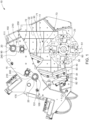
- Figures 1 and 2 show a horizontal shaft impact crusher 10 of the invention provided with a curtain adjustment device 20.
- the horizontal shaft impact crusher 10 comprises a housing 15 having an inlet 30 for receiving material to be crushed, an outlet 40 for material that has been crushed and an impeller 50 within the housing 15.
- a crusher motor not illustrated for reasons of maintaining clarity of illustration, is operative for rotating a horizontal shaft 60 on which the impeller 50 is mounted.
- the impeller 50 may rotate around the shaft 60. In either case, the impeller 50 is operative for rotating around a horizontal axis, coinciding with the centre of the horizontal shaft 60.
- the housing 15 is provided with a plurality of wear protection plates 22 that are operative for protecting the walls of the housing 15 from abrasion and from impact by the material to be crushed. Furthermore, the housing 15 comprises a bearing 23 for the horizontal shaft 60. A lower feed plate (not shown) and an upper feed plate (not shown) are arranged at the inlet 30. The feed plates are operative for providing the material fed to the crusher 10 with a suitable direction with respect to the impeller 50.
- the housing 15 houses a first upper curtain 70, and a second lower curtain 80.
- Each curtain 70,80 comprises at least one wear plate 71,81 against which material may be crushed.
- An upper end 72 of the first curtain 70 is mounted on a horizontal first pivot shaft 90 extending between first and second oppositely disposed pivot points 110,120 defined by respective openings 111,121 in the housing 15 so that the first pivot shaft 90 is suspended in the housing 15.
- an upper end 82 of the second curtain 80 is mounted on a horizontal second pivot shaft 100 extending between first and second oppositely disposed pivot points 130,140 defined by respective openings 131,141 in the housing 15 so that the second pivot shaft 100 is also suspended in the housing 15.
- the illustrated impeller 50 has four beater elements 51, each such beater element 51 having a bent shape, as shown particularly in Figure 1 .
- the area formed between the impeller 50 and the first and second curtains 70,80 can be called a crushing chamber 11 of the crusher 10.
- Material to be crushed first reaches the first curtain 70, being located upstream of the second curtain 80 as seen with respect to the direction of travel of the material.
- the material is directed towards the impeller 50 rotating at, typically, 400-850 rpm.
- the material is hit by the beater elements 51 it is crushed and accelerated against the wear plates 71 of the first curtain 70 where further crushing occurs.
- the material bounces back from the first curtain 70 and is crushed further against material travelling in the opposite direction and, again, against the beater elements 51.
- the material has been crushed to a sufficiently small size it moves further down the crusher chamber 11 and is accelerated, by means of the beater elements 51, towards the wear plates 81 of the second curtain 80, being located downstream of the first curtain 70.
- the material moves freely around in the crushing chamber 11 and is crushed against the beater elements 51, against the wear plates 71,81 respectively of the curtains 70,80 and against other pieces of material circling around, at a high velocity, in the crusher 10.
- a curtain adjustment device 20 is provided on each pivot shaft 90,100 towards a free end of each pivot shaft 90,100 and is axially rotatable to adjust and fix the position of the curtains 70,80. Accordingly, by axial rotation of the adjustment device 20 on the pivot shaft 90, the first curtain 70 may be pivoted around the first pivot shaft 90 until an optimum distance between a second lower end or toe 73 of the first curtain 70 and the impeller 50 has been obtained, with respect to the properties, as regards, e.g., size and hardness, of the material to be crushed. Similarly, by axial rotation of the adjustment device 20 on the pivot shaft 100, the second curtain 80 may be pivoted around the second pivot shaft 100 until a desired distance between the impeller 50 and a second end or toe 83 of the second curtain 80 has been obtained.
- the first pivot shaft 90 extends beyond each opening 111,121 in the housing to define first and second free ends 150,160 of the first pivot shaft 90 and a curtain adjustment device 20 is mounted on both the first free end 150 and the second free end 160.
- the second pivot shaft 100 extends beyond each opening 131,141 in the housing 15 to define first and second free ends 170,180 of the second pivot shaft 100 and a curtain adjustment device 20 is mounted on the first free end 170 and the second free end 180.
- a curtain adjustment device 20 can be provided at either free end 150,160 and 170,180 of the pivot shafts 90,100 respectively.
- the free ends 150,160,170,180 can be protected with a protective cover 151.
- FIG 3 shows an enlarged perspective view from the rear and one side of the upper curtain adjustment device 20 of Figure 2 at the pivot shaft 90 - the other adjustment devices 20 being identical in structure.
- the adjustment device 20 is made up of an axially rotatable driven member 190 mounted on the free end 150 of the pivot shaft 90 so that axial rotation of the driven member 190 by a drive 200 mounted on the housing 15 effects rotation of the pivot shaft 90 to in turn adjust the position of the curtain 70 relative to the impeller 50.
- the driven member 190 is an axially rotatable plate 210 mounted on the free end 150 of the pivot shaft 190 and more particularly an annular plate 220 provided with a pivot shaft receiving opening 230 shaped, sized and contoured to receive the free end 150 of the pivot shaft 90 in a mating relationship.
- the pivot shaft receiving opening 230 and the first free end 150 of the first pivot shaft 90 are both generally square in shape to prevent rotation of the first pivot shaft 90 relative to the axially rotatable plate 210.
- the annular plate 220 is shaped to define a cam-like protrusion 240 which extends laterally or radially outwards from the pivot shaft receiving opening 230 and is generally shaped to define a sector of a circle.
- the annular plate can have alternate shapes.
- the protrusion 240 is provided with peripheral teeth 250 at its outer curved edge 241 which are engageable with the drive 200 which in the present embodiment is a drive gear 260 mounted on the housing 15.
- the drive gear 260 is provided with complementary gear teeth 261 for meshing with the peripheral teeth 250 and is powered by a motor 270 mounted to the housing via a mounting bracket 271 which also serves to cover the drive gear 260.
- the motor 270 is activated to rotate the drive gear 260 to in turn effect axial rotation of the axially rotatable plate 210.
- the pivot shaft 90 is rotated about is longitudinal axis to adjust the position of the curtain 70 and hence the CSS and the like as required.
- the drive 200 can be a linear drive instead of the drive gear 260 which is engageable with the laterally extending cam-like protrusion 240.
- a suitable linear drive is a hydraulic ram and cylinder and a linkage can be provided between the hydraulic ram and cylinder to effect rotation of the annular plate 220.
- the linear drive can be a pneumatic linear drive or a mechanical linear drive.
Landscapes
- Engineering & Computer Science (AREA)
- Food Science & Technology (AREA)
- Crushing And Pulverization Processes (AREA)
Priority Applications (1)
| Application Number | Priority Date | Filing Date | Title |
|---|---|---|---|
| EP22199059.1A EP4344779A1 (de) | 2022-09-30 | 2022-09-30 | Prallbrecher mit horizontaler welle |
Applications Claiming Priority (1)
| Application Number | Priority Date | Filing Date | Title |
|---|---|---|---|
| EP22199059.1A EP4344779A1 (de) | 2022-09-30 | 2022-09-30 | Prallbrecher mit horizontaler welle |
Publications (1)
| Publication Number | Publication Date |
|---|---|
| EP4344779A1 true EP4344779A1 (de) | 2024-04-03 |
Family
ID=83546833
Family Applications (1)
| Application Number | Title | Priority Date | Filing Date |
|---|---|---|---|
| EP22199059.1A Withdrawn EP4344779A1 (de) | 2022-09-30 | 2022-09-30 | Prallbrecher mit horizontaler welle |
Country Status (1)
| Country | Link |
|---|---|
| EP (1) | EP4344779A1 (de) |
Citations (4)
| Publication number | Priority date | Publication date | Assignee | Title |
|---|---|---|---|---|
| DE3911086A1 (de) * | 1988-10-10 | 1990-04-12 | Gronholz Claus | Prallbrecher |
| DE9106099U1 (de) * | 1991-05-17 | 1992-09-17 | O & K Orenstein & Koppel Ag, 1000 Berlin | Prallbrecher |
| WO2005094998A1 (en) * | 2004-03-30 | 2005-10-13 | Officine Meccaniche Di Ponzano Veneto S.P.A. | Crusher for rubble and similar |
| EP3023155A1 (de) * | 2014-11-12 | 2016-05-25 | Sandvik Intellectual Property AB | Vorrichtung zum positionieren des rotors eines prallbrechers mit horizontaler welle |
-
2022
- 2022-09-30 EP EP22199059.1A patent/EP4344779A1/de not_active Withdrawn
Patent Citations (4)
| Publication number | Priority date | Publication date | Assignee | Title |
|---|---|---|---|---|
| DE3911086A1 (de) * | 1988-10-10 | 1990-04-12 | Gronholz Claus | Prallbrecher |
| DE9106099U1 (de) * | 1991-05-17 | 1992-09-17 | O & K Orenstein & Koppel Ag, 1000 Berlin | Prallbrecher |
| WO2005094998A1 (en) * | 2004-03-30 | 2005-10-13 | Officine Meccaniche Di Ponzano Veneto S.P.A. | Crusher for rubble and similar |
| EP3023155A1 (de) * | 2014-11-12 | 2016-05-25 | Sandvik Intellectual Property AB | Vorrichtung zum positionieren des rotors eines prallbrechers mit horizontaler welle |
Similar Documents
| Publication | Publication Date | Title |
|---|---|---|
| EP2376228B1 (de) | Zerkleinerer mit horizontalem welleneinschlag | |
| US3058676A (en) | Rock crusher | |
| JP2021531970A (ja) | 材料を粉砕するための粉砕機システムおよび方法 | |
| US20150190813A1 (en) | Horizontal shaft impact crusher feed chute | |
| EP0564485B1 (de) | Holzzerkleinerungsvorrichtung | |
| US4136833A (en) | Renewable tip hammer for a crusher | |
| EP4344779A1 (de) | Prallbrecher mit horizontaler welle | |
| US5544820A (en) | Clear-trajectory rotary-driven impact comminuter | |
| US2767928A (en) | Plural stage impact breaker with impacting rotors and adjacent deflector screen grates | |
| EP3865214B1 (de) | Verbesserter olivenzerkleinerer | |
| US20070272779A1 (en) | Micron hammermill | |
| JP5567398B2 (ja) | 粉砕装置 | |
| EP3023155B1 (de) | Vorrichtung zum positionieren des rotors eines prallbrechers mit horizontaler welle | |
| EP4344781A1 (de) | Prallbrecher mit horizontaler welle | |
| CN215312916U (zh) | 一种耐用型粘土粉碎机 | |
| US3667694A (en) | Material reducing hammer mill | |
| US10710092B2 (en) | Discharge grates for reduction mills | |
| US20090184187A1 (en) | Concrete crusher | |
| EP4344782A1 (de) | Prallbrecher mit horizontaler welle | |
| KR101571873B1 (ko) | 곡물분쇄장치 | |
| JP4276316B2 (ja) | 遠心破砕機のロ−タ | |
| US2675969A (en) | Impact apparatus for disintegrating solids | |
| CN110636905A (zh) | 冲击式破碎机 | |
| SU532362A1 (ru) | Молоткова дробилка | |
| RU2365413C1 (ru) | Вихревая мельница |
Legal Events
| Date | Code | Title | Description |
|---|---|---|---|
| PUAI | Public reference made under article 153(3) epc to a published international application that has entered the european phase |
Free format text: ORIGINAL CODE: 0009012 |
|
| STAA | Information on the status of an ep patent application or granted ep patent |
Free format text: STATUS: THE APPLICATION HAS BEEN PUBLISHED |
|
| AK | Designated contracting states |
Kind code of ref document: A1 Designated state(s): AL AT BE BG CH CY CZ DE DK EE ES FI FR GB GR HR HU IE IS IT LI LT LU LV MC MK MT NL NO PL PT RO RS SE SI SK SM TR |
|
| STAA | Information on the status of an ep patent application or granted ep patent |
Free format text: STATUS: THE APPLICATION IS DEEMED TO BE WITHDRAWN |
|
| 18D | Application deemed to be withdrawn |
Effective date: 20241005 |