EP4344858B1 - Dispositif de poudrage pour la dépoudre d'objets fabriqués en impression 3d - Google Patents
Dispositif de poudrage pour la dépoudre d'objets fabriqués en impression 3d Download PDFInfo
- Publication number
- EP4344858B1 EP4344858B1 EP23181177.9A EP23181177A EP4344858B1 EP 4344858 B1 EP4344858 B1 EP 4344858B1 EP 23181177 A EP23181177 A EP 23181177A EP 4344858 B1 EP4344858 B1 EP 4344858B1
- Authority
- EP
- European Patent Office
- Prior art keywords
- depowdering
- construction
- container
- construction container
- base
- Prior art date
- Legal status (The legal status is an assumption and is not a legal conclusion. Google has not performed a legal analysis and makes no representation as to the accuracy of the status listed.)
- Active
Links
Images


Classifications
-
- B—PERFORMING OPERATIONS; TRANSPORTING
- B29—WORKING OF PLASTICS; WORKING OF SUBSTANCES IN A PLASTIC STATE IN GENERAL
- B29C—SHAPING OR JOINING OF PLASTICS; SHAPING OF MATERIAL IN A PLASTIC STATE, NOT OTHERWISE PROVIDED FOR; AFTER-TREATMENT OF THE SHAPED PRODUCTS, e.g. REPAIRING
- B29C64/00—Additive manufacturing, i.e. manufacturing of three-dimensional [3D] objects by additive deposition, additive agglomeration or additive layering, e.g. by 3D printing, stereolithography or selective laser sintering
- B29C64/30—Auxiliary operations or equipment
- B29C64/35—Cleaning
-
- B—PERFORMING OPERATIONS; TRANSPORTING
- B22—CASTING; POWDER METALLURGY
- B22F—WORKING METALLIC POWDER; MANUFACTURE OF ARTICLES FROM METALLIC POWDER; MAKING METALLIC POWDER; APPARATUS OR DEVICES SPECIALLY ADAPTED FOR METALLIC POWDER
- B22F10/00—Additive manufacturing of workpieces or articles from metallic powder
- B22F10/60—Treatment of workpieces or articles after build-up
- B22F10/68—Cleaning or washing
-
- B—PERFORMING OPERATIONS; TRANSPORTING
- B33—ADDITIVE MANUFACTURING TECHNOLOGY
- B33Y—ADDITIVE MANUFACTURING, i.e. MANUFACTURING OF THREE-DIMENSIONAL [3D] OBJECTS BY ADDITIVE DEPOSITION, ADDITIVE AGGLOMERATION OR ADDITIVE LAYERING, e.g. BY 3D PRINTING, STEREOLITHOGRAPHY OR SELECTIVE LASER SINTERING
- B33Y40/00—Auxiliary operations or equipment, e.g. for material handling
- B33Y40/20—Post-treatment, e.g. curing, coating or polishing
-
- B—PERFORMING OPERATIONS; TRANSPORTING
- B22—CASTING; POWDER METALLURGY
- B22F—WORKING METALLIC POWDER; MANUFACTURE OF ARTICLES FROM METALLIC POWDER; MAKING METALLIC POWDER; APPARATUS OR DEVICES SPECIALLY ADAPTED FOR METALLIC POWDER
- B22F10/00—Additive manufacturing of workpieces or articles from metallic powder
- B22F10/70—Recycling
- B22F10/73—Recycling of powder
Definitions
- the present invention relates to a depowdering device for depowdering at least one three-dimensional object from unconsolidated building material, created by layer-by-layer application and selective solidification of a powdered building material within a pot-shaped building container as part of a construction process, wherein the building container has a construction container side wall, a container opening and a construction container base which is movable within a construction container side wall and which assumes a specific position within the construction container side wall depending on the construction progress, according to the preamble of claim 1.
- the upwardly open build container or interchangeable container is arranged in a build chamber, which can also form a component of the depowdering device. This means that it can be removed from the build chamber and then inserted into the depowdering device to remove any unsolidified powder from the object, a process also known as depowdering.
- the build container floor which can be moved vertically along the side wall of the build container, is arranged in the build container.
- a build platform, on which the object has been built by layering and selectively solidifying the powdered build material, can rest on the build container floor.
- a generic depowdering device is made of EP 3 068 606 B1 This document proposes that after removing a swap body from an unpacking station, in which the construction container with the assembled object is located, a vibration is applied to the swap body from the outside to assist in removing powder from the object. For this purpose, a vibration generator must be attached to the swap body.
- the object of the invention is to provide a depowdering device that enables the depowdering of objects with minimal effort. This object is achieved according to the invention by the features of claim 1.
- the production of the at least one three-dimensional object, such as a component or model, which is then unpacked in the depowdering device according to the invention, takes place in a layered construction process with the aid of computer data, in which thin layers of loose powdered building material are repeatedly applied to a construction platform and each individual layer is selectively solidified to form a component or model cross-section. Solidification takes place, for example, chemically, by using printing technology to selectively apply droplets of adhesive to defined areas of the layers of loose powdered building material. Alternatively, it is possible to selectively fuse or sinter loose powdered building material with high-energy (laser) radiation.
- laser high-energy
- An object should therefore be understood as a workpiece or component manufactured together with the build platform, or the workpiece or component alone without a build platform.
- the unpacking or cleaning of the at least one object from loose, non-solidified powdered building material in the depowdering device can include the complete unpacking of the object from the cake of loose building material or powder or merely a cleaning of residues of loose powder or building material from the at least one object and optionally also from the building platform and possibly also from support structures which are still present on the at least one object after the unpacking.
- the invention is based on a depowdering device for depowdering at least one three-dimensional object from unconsolidated building material, which object has been created by layer-by-layer application and selective solidification of a powdered building material within the framework of a construction process within a pot-shaped construction container, wherein the construction container has a construction container side wall, a container opening and a construction container base which is movable within a construction container side wall and which takes up a specific position within the construction container side wall depending on the construction progress, wherein the depowdering device comprises at least the following: a construction container designed and equipped to receive the construction container A receiving device, a pivoting device that interacts with the receiving device such that the receiving device can be pivoted about at least one axis by the pivoting device, and a clamping device with at least one clamping element for clamping the construction container to or in the receiving device.
- clamping should be understood broadly here and encompass any fixing or defined holding of the construction container to or in the receiving device.
- the invention is characterized in that the clamping device is designed and configured to clamp the construction container floor, in particular exclusively on the construction container floor, at the at least one clamping element in a clamping position, by physical contact of the at least one clamping element with the construction container floor, and to release the construction container floor from the at least one clamping element in a release position, and in that at least one vibration generator is provided which is connected to the at least one clamping element of the clamping device by direct or indirect physical contact in such a way that vibrations and/or knocking generated by the vibration generator are transmitted to the at least one clamping element by means of structure-borne sound conduction.
- the clamping device is designed and configured such that the construction container can preferably be clamped exclusively on or in the receiving device by the at least one clamping element.
- Structure-borne sound refers to vibrations, oscillations, or impacts that propagate essentially entirely within a solid body or along solid bodies in physical contact with one another, such as in the at least one clamping element that is in direct or indirect physical contact with the vibration generator.
- Indirect physical contact means that at least one additional solid body can be arranged between the vibration generator and at least one clamping element, which then (directly) contacts the vibration generator and the at least one clamping element. Therefore, structure-borne sound differs from airborne sound, in which vibrations or oscillations propagate in gases.
- the invention is therefore based on the idea that the vibration generator, in particular exclusively in the clamping position of the at least one tensioning element is transmitted to the at least one tensioning element and then specifically transmitted by the latter to the construction container floor tensioned by the latter, with which it is in direct body contact in the clamping position.
- the structure-borne sound can be transmitted to the build platform and from there to the object.
- the vibrations to which the object is then excited by the structure-borne sound transmitted (indirectly) by the vibration exciter contribute to the detachment of residues of loose powder or construction material from the object and also from the build platform, and possibly also from support structures present on at least one object.
- the at least one clamping element has an advantageous dual function, serving, on the one hand, to clamp the construction container in or on the receiving device and, on the other hand, as a physical conducting element for the structure-borne noise generated by the vibration generator.
- the vibration exciter is simultaneously connected to the construction container floor in a single step in a structure-borne noise-conducting manner. This eliminates the need for a separate attachment of the vibration exciter to the construction container floor and its separate removal from the construction container floor when removing the construction container from the receiving device.
- the receiving device has a receiving basket for receiving the construction container and a base, wherein the receiving basket is provided with one side of the floor and the tensioning device is arranged essentially on the other side of the floor facing away from the one side.
- the floor can have at least one through-opening through which the at least one clamping element protrudes at least in the clamping position in order to be able to clamp the construction container floor by body contact.
- the at least one tensioning element can extend through the at least one through-opening in the floor without contact. This measure therefore also contributes to a concentration of the structure-borne sound in the construction container floor.
- the clamping device can be a structural unit movable relative to the floor by at least one actuator, on or in which the at least one vibration generator and the at least one clamping element are connected to each other in a structure-borne sound-conducting manner.
- the actuator can, for example, be supported on the one hand on the structural unit and on the other hand on a frame or a housing of the depowdering device.
- the actuator can also comprise at least one pneumatic cylinder.
- pneumatic cylinders during operation, comprise a piston guided within a pneumatic cylinder housing and loaded by an air cushion. This air cushion then acts as a damping element with respect to the structure-borne sound emitted by the vibration exciter into the assembly.
- the assembly may also further comprise a mounting plate on which at least the vibration generator and the at least one clamping element are arranged.
- vibration decoupling means may also be arranged on the mounting plate in such a way that they point toward the floor.
- the actuator can be controlled by a control system in such a way that the actuator moves the structural unit between a first position approaching the ground, in which the at least one clamping element has the clamping position can assume or is ready to assume the clamped position or the unclamped position, and can move to a second position remote from the ground, in which the at least one clamping element assumes the unclamping position.
- the clamping of the construction container floor can then be carried out by the at least one clamping element, and the structure-borne sound-conducting connection of the vibration exciter to the construction container floor can be established in a single step.
- the vibration decoupling means when the structural unit is guided into the first position near the ground, the vibration decoupling means can come into contact with the other side of the ground.
- the vibration decoupling means can comprise at least one elastic element, in particular made of an elastomer. Vibration decoupling means can prevent or impede the propagation of structure-borne sound from the structural unit to the ground of the receiving device, particularly when the structural unit rests on the ground in an upside-down position of the construction container, as described below.
- the vibration generator can also be controlled by a controller such that it is activated at least in the clamping position of the at least one clamping element in order to transmit structure-borne sound to the at least one clamping element.
- the vibration generator preferably generates periodic vibrations in the ultrasonic range or ultrasonic vibrations. However, periodic vibrations of any frequency are possible.
- the vibration generator can also be designed as a vibrator or tapper in order to excite the at least one clamping element by tapping. The tapping can occur once, repeatedly, irregularly, or periodically.
- the depowdering device can also comprise a depowdering chamber, in particular a powder-tight one, in which the receiving device is arranged.
- the receiving device can have a lid movably mounted on the receiving basket, wherein in a lifted position of the lid the construction container is received in the receiving basket in a substantially upright position, in which the container opening points substantially upwards, and can be removed from the receiving basket can be closed, and in a lowered position of the lid, the container opening of the construction container and/or an opening of the receiving basket can be closed.
- the receiving basket may then not be powder-tight.
- the receiving basket may be powder-tight, and the lid may then close the receiving basket in a powder-tight manner.
- This design may be suitable for a construction container in which the container opening is uncovered or open (only) before loading the receiving device and is then covered by the lid in the lowered position after loading in the receiving device so that the construction container is then (powder-)tight.
- the lid can be driven rotationally and/or translationally by at least one actuator such as an electric motor and can thus be movable relative to the receiving basket, wherein the actuator is controlled, for example, by an electronic control system.
- at least one actuator such as an electric motor and can thus be movable relative to the receiving basket, wherein the actuator is controlled, for example, by an electronic control system.
- the construction container can already be provided with a lid before loading or during loading into the receiving device, which tightly seals the container opening.
- the receiving device can then also be designed and configured to receive the construction container including the lid in this already sealed state.
- the pivoting device is designed and controlled by a controller such that the receiving device can be pivoted at least once about the at least one axis between a loading and unloading position provided for loading and unloading the construction container, in which the lid points substantially upwards, and an emptying position provided for emptying the construction container of unconsolidated building material, in which the lid points substantially downwards in the direction of gravity.
- the lid In order to remove the unconsolidated building material detached from the object and/or the building platform from the building container, particularly in the emptying position, the lid can be provided with at least one through-opening through which the building material can then flow out of the building container due to the effect of gravity and/or by suction.
- the depowdering device comprises a housing in which the depowdering chamber is formed.
- the depowdering chamber is particularly designed to be powder-tight and/or gas-tight, but construction containers can be fed in and out through at least one opening in the depowdering chamber, which can be opened and closed, for example, by a closure element.
- the depowdering chamber can have a funnel-shaped base arranged in such a way that it can receive the unconsolidated build material flowing downward from the at least one object as a result of or with the aid of gravity through the at least one through-opening in the lid.
- This build material then located in the funnel-shaped base, can then be removed from the depowdering chamber, for example, through a closable opening arranged in a funnel neck of the base, and reused for a subsequent construction process.
- a ventilation device can be provided through which the depowdering chamber can be flowed through by a flow of gas, in particular external air, which is fed into the depowdering chamber from the outside via a supply opening of the housing and can be discharged from the depowdering chamber by means of an outlet opening of the housing, wherein the ventilation device is designed such that the gas flows around the construction container accommodated in the pivoting device.
- a flow of gas in particular external air
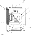
- Fig. 1 shows a perspective view of a preferred embodiment of a depowdering device 100 for depowdering, here for example, a three-dimensional object 9 created by layer-by-layer application and selective solidification of a powdered construction material within the framework of a construction process ( Fig. 5A , 5B ) of unconsolidated building material according to the invention.
- the object 9 was created in a construction device (not shown here), which includes a powder- and gas-tight construction chamber, by layer-by-layer application and selective solidification of a powdered construction material, e.g., plastic or metal powder, onto a construction platform 11 during a construction process that takes place in an atmosphere within the construction chamber that contains, for example, at least one inert protective gas.
- a construction container 1 is arranged in the construction chamber, in which the construction process of the object 9 takes place and in which it is also arranged in the depowdering device 100 after completion of the construction process.
- the construction container 1 is, for example, pot-shaped and has a container opening 15, a construction container side wall 32, and a construction container base 30 that is vertically movable with respect to the construction container side wall 32 and occupies a specific level within the construction container side wall 32 depending on the construction progress.
- the container opening 15 points upwards, for example, relative to the position of use of the construction container 1 during the construction of the object 9.
- the object 9 is formed in the construction container 1 Built layer by layer.
- an object 9 is built on the build platform 11 and then (initially) forms a unit with the build platform 11. Later, the object 9 is separated from the build platform 11, which can then be used to build another object.
- the construction container 1 is also called a swap body or job box.
- Fig. 5A and Fig. 5B A preferred embodiment of the construction container 1 is shown, which has the construction container base 30 which is axially movable within the construction container side wall 32 and which, during the construction process, occupies a specific vertical level within the construction container side wall 32 depending on the construction progress.
- the construction container base 30 is in an upper position near the container opening 15 and is then displaced further and further downwards as the construction process progresses until it occupies a lowest position in which it is approximately flush with the lower edges of the construction container side wall 32.
- the depowdering device 100 includes a housing with an unpacking chamber 4, in which the object 9 is at least partially depowdered or cleaned of surrounding and/or non-solidified powdered building material remaining in openings or channels of the object 9 within the framework of a depowdering process.
- the depowdering device 100 comprises a receiving device 16 with a lid 3, a pivoting device 2 and a movable roller shutter 5 to enable loading and unloading of the construction container 1 with respect to the unpacking chamber 4.
- the receiving device 16 comprises, in addition to the lid 3, for example, a receiving basket 24 which is open at the side through a lateral basket opening and at the top through an upper basket opening, in which the construction container 1 can be received with little play in a substantially upright position, wherein the container opening 15 of the construction container 1 then preferably points upwards.
- the transport of the construction container 1 into the unpacking chamber 4 and there into the receiving device 16 takes place, for example, horizontally in the direction indicated by the arrow 23 in Fig. 2 symbolized horizontal direction, for example by an outer roller conveyor not shown here.
- This outer roller conveyor can be
- This outer roller conveyor can be
- the receiving device must be continued by a separate inner roller conveyor at the same level.
- the lid 3 and the receiving basket 24 are pivotally mounted relative to one another, for example in the region of the upper basket opening of the receiving basket 24, about a first, for example horizontal, pivot axis 26.
- a first pivot actuator coordinated by the electronic control system, is provided for this relative movement.
- the lid 3 can be pivoted relative to the stationary receiving basket 24 and the construction container 1 received therein into a raised position, in which loading and unloading of a construction container is possible and in which the lid is also lifted from the construction container opening 15 if such a container is received in the receiving basket 24.
- Fig. 2 shows the loading and unloading position of the receiving device 16 or the lid 3, which is then folded upwards by the receiving basket 24.
- the lid can also be pivoted into a lowered or working position, in which it tightly closes the construction container opening 15.
- the lid 3 and the receiving basket 24 could also perform a translational movement relative to each other in order to assume the loading and unloading position, as well as the working position.
- the receiving device 16 can be pivoted as a whole by a pivoting device 2, for example about a second horizontal pivot axis 27, by driving a second pivot actuator controlled in a coordinated manner by the control system into any angular positions between 0 degrees and 360 degrees, at least once and preferably several times in succession.
- the lid 3 has a pyramid-shaped lid base 19, for example, with an outlet opening 21 at its apex, to which, for example, a suction hose of a suction device can be connected.
- the build-up material cleaned from the object 9 could also flow out through the outlet opening 21 solely due to gravity if the receiving device 16 is in the Fig. 3 shown emptying position (head position).
- the lid 3 can be pivotally driven relative to the receiving basket 24 by the first pivot actuator about the first pivot axis 26 between the position lifted from the receiving basket 24 or from the construction container 1 and the working position, in which the lid 3 closes the container opening 15 of the construction container 1 received in the receiving basket 24, in particular in a powder-tight manner.
- top and bottom or “upright” in the sense of this description refer to the position of use of the depowdering device 100.
- FIG. 2 shows a side view of the depowdering device 100 of Fig. 1 in a situation in which the construction container 1 with the object 9 accommodated therein is loaded into the unpacking chamber 4 and there into the receiving device 16 in its initial position, e.g., via the open roller shutter 5 of the unpacking chamber 4. Construction material that remained unconsolidated during the construction process described above then still adheres to the object 9.
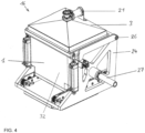
- the lid 3 is folded upwards relative to the receiving basket 24, for example, into the raised position. Then the construction container 1 is moved as indicated by the arrow 23 into Fig. 2 symbolized via a lateral receiving opening of the receiving basket 24 into the receiving basket 24, for example standing or upright (container opening 15 points upwards) and there, for example, by a Fig. 5a , Fig. 5B and Fig. 6 shown clamping device 29 of the receiving device 16 in the receiving basket 24.
- the construction container 1 is then located in the receiving basket 16 in a substantially upright position, in which the container opening 15 points substantially upward, i.e., against the direction of gravity.
- a substantially upright position means that this upright position can also deviate from a purely vertical position by a certain amount.
- the lid 3 is pivoted downwards into the working position in such a way that it closes the container opening 15 of the construction container 1 in a powder-tight manner.
- a bottom 6 of the receiving basket 24 has a vertical distance from the lid 3 in the working position, which in approximately corresponds to the height of the construction container 1.
- loose construction material can therefore only flow out of the construction container 1 through the outlet opening 21 formed in the lid 3.
- the clamping device 29 has, for example, clamping cylinders 17 with clamping openings 31, into which clamping pins 25 formed on the construction container base 30 can positively engage in a clamping position of the clamping device 29 described below in order to fix the construction container 1 in the receiving basket 24.
- the clamping pins 25 of the construction container base 30 are then released from the clamping openings 31 of the clamping cylinders 17 in a release position of the clamping device 29 described below.
- the receiving device 16 has a base 6, wherein the receiving basket 24 is connected to one side of the base 6 and the clamping device 29 is arranged substantially on the other side of the base 6 facing away from the one side.
- the clamping device 29 represents a structural unit movable relative to the base 6 by an actuator, here for example a pneumatic cylinder 18, as shown in the Figures 5A , 5B and 6
- This assembly 8 comprises a docking plate 7, on which a vibration generator 10 and the clamping cylinders 17 and vibration decoupling means 28 facing the floor 6, here in the form of rubber cylinders, for example, are arranged.
- the pneumatic cylinder 18 is supported, for example, on the one hand on the assembly 8 and on the other hand on a housing of the unpacking chamber 4.
- vibrations generated by the vibration generator 10 can be transmitted as structure-borne sound, i.e., through vibrations propagating in solid bodies, through the docking plate 7 into the clamping cylinders 17.
- the vibration generator 10 is controlled in a coordinated manner, for example, by the electronic control system (not shown here), which also executes the actions or functions described above.
- the base 6 of the receiving device 16 has through-openings 13 through which the clamping cylinders 17 can pass, for example, in the unclamping position ( Fig. 5A ) and in the clamping position ( Fig. 5B , Fig. 6 ) of the clamping device 29 or the structural unit 8 preferably protrude without contact with the base 6.
- the pneumatic cylinder 18 is controlled by the control system in such a way that it moves the structural unit 8 or the clamping device 29 between a first position ( Fig. 5B Fig. 6 ), in which the clamping cylinders 17 assume the clamping position in relation to the clamping pins 25 of the construction container base 30, and a second position remote from the base 6, in which the clamping cylinders 17 assume the unclamping position ( Fig. 5A ) .
- the pneumatic cylinder 18 moves the structural unit 8 or the clamping device 29 vertically relative to the base 6 of the receiving device 16.
- the construction container floor 30 is therefore clamped by the clamping cylinders 17 on the clamping device 29, whereby a structure-borne sound-conducting connection of the vibration generator 10 with the construction container floor 30 is automatically established in a single step ( Fig. 5B Fig. 6 ).
- the structure-borne sound-conducting contact between the clamping cylinders 17 and the clamping pins 25 of the construction container base 30 is then preferably released ( Fig. 5A ).
- the Fig. 5A The relaxation position shown is assumed, for example, in the loading and unloading position for loading and unloading the construction container 1, the clamping position, for example, at least when unconsolidated construction material is to be removed from the object 9 or from the construction platform 11 here by the structure-borne sound generated by the vibration generator 10 and transmitted to the object 9, in particular when the receiving device 16 has the Fig. 3 and in Fig. 6 shown emptying position (head position).
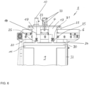
- the vibration generator 10 is preferably controlled by the controller in such a way that it is activated only in the clamped position to generate vibrations. These vibrations are then transmitted as structure-borne sound via the clamping cylinders 17, the clamping pins 25 clamped in the clamping openings 31 therein, the construction container floor 30 to the construction platform 11 (temporarily) firmly connected to the construction container floor 30, and from there to the object 9, as indicated by the arrows in Fig. 6
- the vibration generator produces 10 vibrations in Ultrasonic range.
- any other excitation frequency is also possible.
- the vibration excitation contributes to the flow of the unsolidified build-up material from object 9 or out of the openings and channels of object 9.
- the vibration generator 10 is preferably activated by the control when or after the receiving device 16 has been moved into the Fig. 3 and in Fig. 6 shown emptying position (head position).
- the clamping cylinders 17 extend through openings 13 of the floor 6 without contact with the floor 6.
- the structural unit 8 is preferably supported on the other side of the base 6 via the vibration decoupling means 28.
- These (mechanically soft) vibration decoupling means 28, which consist, for example, of an elastomer, also contribute to ensuring that no high-frequency ultrasound is introduced from the structural unit 8 into the base 6.
- this compressed air represents a damping element with respect to the structure-borne sound emitted by the vibration exciter 10 into the structural unit 8.
- the clamping position of the structural unit 8 or the clamping device 29 can also be adjusted vertically by the control system in such a way that a clear gap 34 is still present between an inner stop flange 20 arranged at the lower edge of the construction container side wall 32 and the container bottom 30, which gap 34 prevents or limits the transmission of structure-borne sound to the construction container side wall 32.
- These measures also contribute to a concentration of structure-borne sound in the construction container floor 30 and thus in the object 9.
- Fig. 3 and Fig. 6 show the depowdering device 100 of Fig. 1 in a situation in which the construction container 1, received in the receiving basket 24 and closed at its container opening 15 by the lid 3 in the working position, is pivoted by the pivoting device 2 about the second pivot axis 26 such that the container opening 15 points essentially downwards, i.e., in the direction of gravity.
- Essentially pointing downwards means that certain deviations from a purely vertical position can also occur, as long as a gravitational component can act on the powdered construction material.
- the swivel device 2 swivels the receiving device 16 with the construction container 1 received therein from the Fig. 1 shown upright and in particular vertical position, in which the container opening 15 of the construction container 1 points substantially upwards, preferably by 180° into the upside-down or emptying position, in which the container opening 15 of the construction container 1 then points substantially downwards, i.e. in the direction of the effect of gravity.
- the pivoting of the construction container 1 into the upside-down position at least a portion of the remaining unsolidified building material 11 detaches from the object 9 and then flows in the direction of the outlet opening 21 of the lid 3, which can be opened and closed by an actuator controlled in a coordinated manner by the electronic control system.
- the vibration generator 10 can be activated in order to intensify or even enable the detachment of unconsolidated build-up material from the object 9 or from channels and openings of the object 9 through the above-described excitation of the object 9 by structure-borne sound.
- the detached build-up material With the outlet opening 21 of the lid 3 open, the detached build-up material can then flow into the unpacking chamber 4 and from there via a drain opening 12 into a collection container for reuse.
- the unconsolidated build-up material could also be directly suctioned off via the outlet opening 21 of the lid 3.
Landscapes
- Chemical & Material Sciences (AREA)
- Engineering & Computer Science (AREA)
- Manufacturing & Machinery (AREA)
- Materials Engineering (AREA)
- Physics & Mathematics (AREA)
- Mechanical Engineering (AREA)
- Optics & Photonics (AREA)
- Auxiliary Methods And Devices For Loading And Unloading (AREA)
- Conveying And Assembling Of Building Elements In Situ (AREA)
Claims (15)
- Dispositif de dépoudrage (100) destiné au dépoudrage d'au moins un objet tridimensionnel (9) de matériau de construction résiduel non consolidé, produit par application par couches et consolidation sélective d'un matériau pulvérulent de construction dans le cadre d'un processus de construction à l'intérieur d'un récipient de construction (1) en forme de pot, dans lequel le récipient de construction (1) présente une paroi latérale (32) de récipient de construction, une ouverture (15) de récipient et un plateau mobile (30) de récipient de construction à l'intérieur d'une paroi latérale (32) de récipient de construction, qui occupe en fonction de la progression de construction un emplacement déterminé à l'intérieur de la paroi latérale (32) de récipient de construction, dans lequel le dispositif de dépoudrage (100) comprend au moins ce qui suit :a) un dispositif de réception (16) conçu et configuré pour la réception du récipient de construction (1),b) un dispositif de pivotement (2) coopérant avec le dispositif de réception (16) de telle façon que le dispositif de réception (16) peut être pivoté autour d'au moins un axe (27) par le dispositif de pivotement (2),c) un dispositif de serrage (19) comportant au moins un élément de serrage (17, 31), destiné au serrage du récipient de construction (1) sur ou dans le dispositif de réception (16), dans lequeld) le dispositif de serrage (19) est conçu et configuré pour, dans une position de fixation du récipient de construction (1), serrer en particulier exclusivement le plateau (30) de récipient de construction sur ledit au moins un élément de serrage (17, 31) par contact physique dudit au moins un élément de serrage (17, 31) avec le plateau (30) de récipient de construction et pour, dans une position de desserrage, libérer le plateau (30) de récipient de construction dudit au moins un élément de serrage (17, 31), caractérisé en ce quee) au moins un générateur de vibrations (10) relié audit au moins un élément de serrage (17, 31) du dispositif de serrage (19) par contact physique direct ou indirect est prévu, de sorte que des vibrations produites par le générateur de vibrations (10) et/ou un battement produit par le générateur de vibrations (10) est/sont transmis(es) audit au moins un élément de serrage (17, 31) par conduction de son solidien.
- Dispositif de dépoudrage selon la revendication 1, caractérisé en ce que le dispositif de réception (16) présente un panier de réception (24) destiné à la réception du récipient de construction (1) et un plateau (6), dans lequel le panier de réception (24) est relié à un côté du plateau (6), et le dispositif de serrage (19) est disposé essentiellement sur l'autre côté du plateau (6), éloigné dudit un côté.
- Dispositif de dépoudrage selon la revendication 2, caractérisé en ce que le plateau (6) présente au moins une ouverture de passage (13) à travers laquelle ledit au moins un élément de serrage (17, 31) s'élève au moins dans la position de serrage afin de pouvoir serrer par contact physique le plateau (30) de récipient de construction.
- Dispositif de dépoudrage selon la revendication 3, caractérisé en ce que ledit au moins un élément de serrage (17, 31) s'élève sans contact à travers ladite au moins une ouverture de passage (13) du plateau (6).
- Dispositif de dépoudrage selon l'une quelconque des revendications 2 à 4, caractérisé en ce que le dispositif de serrage (19) représente un module (8) mobile par rapport au plateau (6) au moyen d'au moins un actionneur (18), module sur ou dans lequel ledit au moins un générateur de vibrations (10) et ledit au moins un élément de serrage (17, 31) sont reliés l'un à l'autre en conduisant le bruit solidien.
- Dispositif de dépoudrage selon la revendication 5, caractérisé en ce que l'actionneur (18) comprend au moins un vérin pneumatique.
- Dispositif de dépoudrage selon la revendication 5 ou 6, caractérisé en ce que le module (8) comprend en outre une plaque de montage (7), sur laquelle sont disposés au moins le générateur de vibrations (10) et ledit au moins un élément de serrage (17, 31).
- Dispositif de dépoudrage selon la revendication 7, caractérisé en ce que des moyens de neutralisation de vibrations (28) sont en outre disposés sur la plaque de montage (7) de telle façon qu'ils sont orientés vers le plateau (6).
- Dispositif de dépoudrage selon l'une quelconque des revendications 5 à 8, caractérisé en ce que l'actionneur (10) est commandé par un dispositif de commande de sorte que l'actionneur (10) peut mouvoir le module (8) entre un premier emplacement rapproché du plateau (6) dans lequel ledit au moins un élément de serrage (17, 31) peut occuper la position de serrage ou est prêt à l'adoption de la position de serrage ou de la position de desserrage, et un second emplacement éloigné du plateau (6) dans lequel ledit au moins un élément de serrage (17, 31) occupe la position de desserrage ou peut occuper la position de desserrage.
- Dispositif de dépoudrage selon les revendications 8 et 9, caractérisé en ce que lorsque le module (8) est amené dans le premier emplacement rapproché du plateau (6), les moyens de neutralisation de vibrations (28) entrent en contact avec l'autre côté du plateau (6).
- Dispositif de dépoudrage selon l'une quelconque des revendications précédentes, caractérisé en ce que le générateur de vibrations (10) est commandé par un dispositif de commande de sorte qu'il est activé au moins dans la position de serrage dudit au moins un élément de serrage (17, 31) afin de transmettre les vibrations audit au moins un élément de serrage (17, 31) sous forme de bruit solidien.
- Dispositif de dépoudrage selon l'une quelconque des revendications précédentes, caractérisé en ce que le générateur de vibrations (10) produit des vibrations dans le domaine des ultrasons.
- Dispositif de dépoudrage selon l'une quelconque des revendications précédentes, caractérisé en ce qu'il comprend une chambre de dépoudrage (4), en particulier étanche aux poudres, dans laquelle est disposé le dispositif de réception (16).
- Dispositif de dépoudrage selon l'une quelconque des revendications 2 à 13, caractérisé en ce que le dispositif de réception (16) présente un couvercle (3) placé de façon mobile sur le panier de réception (24), dans lequel, dans une position relevée du couvercle (3), le récipient de construction (1) est reçu dans le panier de réception (24) en une position sensiblement verticale, dans laquelle l'ouverture (15) de récipient est orientée sensiblement vers le haut, et peut être retiré du panier de réception (24), et dans une position abaissée du couvercle (3), l'ouverture (15) de récipient du récipient de construction (1) et/ou une ouverture du panier de réception (24) peu(ven)t être fermée(s).
- Dispositif de dépoudrage selon l'une quelconque des revendications précédentes, caractérisé en ce que le dispositif de pivotement (2) est conçu de façon telle et commandé de façon telle par un dispositif de commande que le dispositif de réception (16) est pivotable au moins une fois autour dudit au moins un axe (27) entre une position de chargement et déchargement prévue pour charger et décharger le récipient de construction (1), dans laquelle le couvercle (3) est orienté sensiblement vers le haut, et une position de vidage prévue pour vider le récipient de construction (1) de la poudre non consolidée, dans laquelle le couvercle (3) est orienté sensiblement vers le bas en direction de la force de pesanteur.
Applications Claiming Priority (1)
| Application Number | Priority Date | Filing Date | Title |
|---|---|---|---|
| DE102022003575.8A DE102022003575B4 (de) | 2022-09-27 | 2022-09-27 | Entpulverungsvorrichtung zum Entpulvern von im 3D-Druckverfahren entstandenen Objekten |
Publications (3)
| Publication Number | Publication Date |
|---|---|
| EP4344858A1 EP4344858A1 (fr) | 2024-04-03 |
| EP4344858B1 true EP4344858B1 (fr) | 2025-06-18 |
| EP4344858C0 EP4344858C0 (fr) | 2025-06-18 |
Family
ID=87047788
Family Applications (1)
| Application Number | Title | Priority Date | Filing Date |
|---|---|---|---|
| EP23181177.9A Active EP4344858B1 (fr) | 2022-09-27 | 2023-06-23 | Dispositif de poudrage pour la dépoudre d'objets fabriqués en impression 3d |
Country Status (2)
| Country | Link |
|---|---|
| EP (1) | EP4344858B1 (fr) |
| DE (1) | DE102022003575B4 (fr) |
Citations (1)
| Publication number | Priority date | Publication date | Assignee | Title |
|---|---|---|---|---|
| WO2022089933A1 (fr) * | 2020-10-30 | 2022-05-05 | Trumpf Laser- Und Systemtechnik Gmbh | Plaque de substrat pour récipient interchangeable, récipient interchangeable et procédé et appareil pour déballer un objet tridimensionnel produit sur une plaque de substrat ou dans le récipient interchangeable par solidification sélective d'un matériau de construction sous forme de poudre |
Family Cites Families (6)
| Publication number | Priority date | Publication date | Assignee | Title |
|---|---|---|---|---|
| DE102013223407A1 (de) | 2013-11-15 | 2015-05-21 | Eos Gmbh Electro Optical Systems | Vorrichtung und Verfahren zum schichtweisen Herstellen eines dreidimensionalen Objekts sowie zum Auspacken des fertiggestellten Objekts |
| EP3167980A1 (fr) * | 2015-11-13 | 2017-05-17 | SLM Solutions Group AG | Dispositif de déballage permettant l'élimination d'une poudre de matière brute résiduelle |
| GB201600629D0 (en) * | 2016-01-13 | 2016-02-24 | Renishaw Plc | Powder bed fusion apparatus and methods |
| DE102017108080A1 (de) | 2017-04-13 | 2018-10-18 | Trumpf Laser- Und Systemtechnik Gmbh | Vorrichtung und Verfahren zum Entpacken eines durch schichtweises Auftragen hergestellten Objekts |
| DE102020128789A1 (de) | 2020-11-02 | 2022-05-05 | Trumpf Laser- Und Systemtechnik Gmbh | Behälteranordnung einer Entpackungsvorrichtung für eine Fertigungsvorrichtung, Entpackungsvorrichtung mit einer derartigen Behälteranordnung sowie Fertigungsvorrichtung |
| DE202020004634U1 (de) | 2020-11-04 | 2020-11-25 | Solukon Ingenieure GbR (vertretungsberechtigte Gesellschafter: Andreas Hartmann, 86391 Stadtbergen und Dominik Schmid, 86165 Augsburg) | Vorrichtung zur Nachbearbeitung wenigstens eines mit einem additiven Fertigungsverfahren hergestellten Objekts |
-
2022
- 2022-09-27 DE DE102022003575.8A patent/DE102022003575B4/de active Active
-
2023
- 2023-06-23 EP EP23181177.9A patent/EP4344858B1/fr active Active
Patent Citations (1)
| Publication number | Priority date | Publication date | Assignee | Title |
|---|---|---|---|---|
| WO2022089933A1 (fr) * | 2020-10-30 | 2022-05-05 | Trumpf Laser- Und Systemtechnik Gmbh | Plaque de substrat pour récipient interchangeable, récipient interchangeable et procédé et appareil pour déballer un objet tridimensionnel produit sur une plaque de substrat ou dans le récipient interchangeable par solidification sélective d'un matériau de construction sous forme de poudre |
Also Published As
| Publication number | Publication date |
|---|---|
| EP4344858C0 (fr) | 2025-06-18 |
| DE102022003575B4 (de) | 2025-01-23 |
| DE102022003575A1 (de) | 2024-03-28 |
| EP4344858A1 (fr) | 2024-04-03 |
Similar Documents
| Publication | Publication Date | Title |
|---|---|---|
| EP3030403B1 (fr) | Système de revêtement pour imprimante 3d | |
| EP3536424B1 (fr) | Dispositif de nettoyage permettant de nettoyer des objets tridimensionnels | |
| EP3458205B1 (fr) | Élimination de la poussière d'une pièce de prototypage rapide | |
| WO2001010631A2 (fr) | Procede et dispositif de production d'un objet tridimensionnel | |
| EP3609683B1 (fr) | Dispositif et procédé d'extraction d'un objet fabriqué par application de couches | |
| DE102009030113A1 (de) | Verfahren und Vorrichtung zum Zuführen von Fluiden beim schichtweisen Bauen von Modellen | |
| WO2011127897A2 (fr) | Procédé et dispositif de réalisation de modèles tridimensionnels | |
| DE102006041320A1 (de) | Beschichtereinrichtung für eine Bauvorrichtung zur Erstellung von Formteilen aus pulverartigem Baumaterial unter Einbringung von Strahlungsenergie | |
| WO2022089933A1 (fr) | Plaque de substrat pour récipient interchangeable, récipient interchangeable et procédé et appareil pour déballer un objet tridimensionnel produit sur une plaque de substrat ou dans le récipient interchangeable par solidification sélective d'un matériau de construction sous forme de poudre | |
| EP3983203A1 (fr) | Procédé et dispositif permettant la fabrication de pièces mises en forme en 3d par la technique d'impression par couches et au moyen d'un « recoater » à obturation par dépression | |
| WO2017080659A1 (fr) | Dispositif et procédé de fabrication d'un objet tridimensionnel | |
| EP3642038A1 (fr) | Système de levage pour un dispositif et procédé de fabrication générative d'un objet tridimensionnel | |
| EP4344858B1 (fr) | Dispositif de poudrage pour la dépoudre d'objets fabriqués en impression 3d | |
| EP3017933A2 (fr) | Dispositif de soudage par application laser destinee a la fabrication additive d'objets tridimensionnels | |
| EP3740376B1 (fr) | Procédé de déballage d'une pièce imprimée en 3d | |
| DE202020004634U1 (de) | Vorrichtung zur Nachbearbeitung wenigstens eines mit einem additiven Fertigungsverfahren hergestellten Objekts | |
| DE102017220640A1 (de) | Vorrichtung zum Auspacken zumindest eines Bauteils sowie ein Verfahren, um dieses Auspacken zu realisieren | |
| EP3789184B1 (fr) | Dispositif de déballage permettant de déballer des objets créés lors d'un procédé d'impression 3d | |
| EP3986701A1 (fr) | Ensemble d'un dispositif d'impression 3d | |
| DE102018008736A1 (de) | Verfahren und vorrichtung zum herstellen eines dreidimensionalen objekts auf einer bauplattform | |
| EP4159331B1 (fr) | Dispositif de nettoyage pourvu de porte-objet oscillant | |
| DE102020008254B4 (de) | Verfahren und Vorrichtung zum Trennen von Aufbaumaterial von im 3D-Druckverfahren entstandenen Objekten | |
| DE102023122637A1 (de) | Vorrichtung zur Recoater-Reinigung, Partikelmaterialkonditionierung und ihre Verwendung in Verfahren zum schichtweisen Aufbau von Formteilen | |
| DE102021002050A1 (de) | Vorrichtung und Verfahren zum Trennen von unverfestigt verbliebenem Aufbaumaterial von wenigstens einem im 3D-Druckverfahren entstandenen Objekt | |
| DE2343174C3 (de) | Verfahren und Vorrichtung zum feuerfesten Zustellen metallurgischer Gefäße durch Vibration |
Legal Events
| Date | Code | Title | Description |
|---|---|---|---|
| PUAI | Public reference made under article 153(3) epc to a published international application that has entered the european phase |
Free format text: ORIGINAL CODE: 0009012 |
|
| STAA | Information on the status of an ep patent application or granted ep patent |
Free format text: STATUS: THE APPLICATION HAS BEEN PUBLISHED |
|
| AK | Designated contracting states |
Kind code of ref document: A1 Designated state(s): AL AT BE BG CH CY CZ DE DK EE ES FI FR GB GR HR HU IE IS IT LI LT LU LV MC ME MK MT NL NO PL PT RO RS SE SI SK SM TR |
|
| STAA | Information on the status of an ep patent application or granted ep patent |
Free format text: STATUS: REQUEST FOR EXAMINATION WAS MADE |
|
| 17P | Request for examination filed |
Effective date: 20241004 |
|
| RBV | Designated contracting states (corrected) |
Designated state(s): AL AT BE BG CH CY CZ DE DK EE ES FI FR GB GR HR HU IE IS IT LI LT LU LV MC ME MK MT NL NO PL PT RO RS SE SI SK SM TR |
|
| RIC1 | Information provided on ipc code assigned before grant |
Ipc: B22F 10/73 20210101ALN20250123BHEP Ipc: B22F 10/68 20210101ALI20250123BHEP Ipc: B33Y 40/20 20200101ALI20250123BHEP Ipc: B22F 12/00 20210101ALI20250123BHEP Ipc: B29C 64/35 20170101AFI20250123BHEP |
|
| GRAP | Despatch of communication of intention to grant a patent |
Free format text: ORIGINAL CODE: EPIDOSNIGR1 |
|
| STAA | Information on the status of an ep patent application or granted ep patent |
Free format text: STATUS: GRANT OF PATENT IS INTENDED |
|
| RIC1 | Information provided on ipc code assigned before grant |
Ipc: B22F 10/73 20210101ALN20250206BHEP Ipc: B22F 10/68 20210101ALI20250206BHEP Ipc: B33Y 40/20 20200101ALI20250206BHEP Ipc: B22F 12/00 20210101ALI20250206BHEP Ipc: B29C 64/35 20170101AFI20250206BHEP |
|
| INTG | Intention to grant announced |
Effective date: 20250228 |
|
| GRAS | Grant fee paid |
Free format text: ORIGINAL CODE: EPIDOSNIGR3 |
|
| GRAA | (expected) grant |
Free format text: ORIGINAL CODE: 0009210 |
|
| STAA | Information on the status of an ep patent application or granted ep patent |
Free format text: STATUS: THE PATENT HAS BEEN GRANTED |
|
| AK | Designated contracting states |
Kind code of ref document: B1 Designated state(s): AL AT BE BG CH CY CZ DE DK EE ES FI FR GB GR HR HU IE IS IT LI LT LU LV MC ME MK MT NL NO PL PT RO RS SE SI SK SM TR |
|
| REG | Reference to a national code |
Ref country code: GB Ref legal event code: FG4D Free format text: NOT ENGLISH |
|
| REG | Reference to a national code |
Ref country code: CH Ref legal event code: EP |
|
| REG | Reference to a national code |
Ref country code: DE Ref legal event code: R096 Ref document number: 502023001171 Country of ref document: DE |
|
| REG | Reference to a national code |
Ref country code: CH Ref legal event code: EP |
|
| REG | Reference to a national code |
Ref country code: IE Ref legal event code: FG4D Free format text: LANGUAGE OF EP DOCUMENT: GERMAN |
|
| PGFP | Annual fee paid to national office [announced via postgrant information from national office to epo] |
Ref country code: AT Payment date: 20250721 Year of fee payment: 3 |
|
| U01 | Request for unitary effect filed |
Effective date: 20250630 |
|
| U07 | Unitary effect registered |
Designated state(s): AT BE BG DE DK EE FI FR IT LT LU LV MT NL PT RO SE SI Effective date: 20250707 |
|
| PG25 | Lapsed in a contracting state [announced via postgrant information from national office to epo] |
Ref country code: NO Free format text: LAPSE BECAUSE OF FAILURE TO SUBMIT A TRANSLATION OF THE DESCRIPTION OR TO PAY THE FEE WITHIN THE PRESCRIBED TIME-LIMIT Effective date: 20250918 Ref country code: GR Free format text: LAPSE BECAUSE OF FAILURE TO SUBMIT A TRANSLATION OF THE DESCRIPTION OR TO PAY THE FEE WITHIN THE PRESCRIBED TIME-LIMIT Effective date: 20250919 |
|
| PG25 | Lapsed in a contracting state [announced via postgrant information from national office to epo] |
Ref country code: HR Free format text: LAPSE BECAUSE OF FAILURE TO SUBMIT A TRANSLATION OF THE DESCRIPTION OR TO PAY THE FEE WITHIN THE PRESCRIBED TIME-LIMIT Effective date: 20250618 |
|
| PG25 | Lapsed in a contracting state [announced via postgrant information from national office to epo] |
Ref country code: RS Free format text: LAPSE BECAUSE OF FAILURE TO SUBMIT A TRANSLATION OF THE DESCRIPTION OR TO PAY THE FEE WITHIN THE PRESCRIBED TIME-LIMIT Effective date: 20250918 |
|
| U20 | Renewal fee for the european patent with unitary effect paid |
Year of fee payment: 3 Effective date: 20251007 |
|
| PG25 | Lapsed in a contracting state [announced via postgrant information from national office to epo] |
Ref country code: IS Free format text: LAPSE BECAUSE OF FAILURE TO SUBMIT A TRANSLATION OF THE DESCRIPTION OR TO PAY THE FEE WITHIN THE PRESCRIBED TIME-LIMIT Effective date: 20251018 |
|
| PG25 | Lapsed in a contracting state [announced via postgrant information from national office to epo] |
Ref country code: SM Free format text: LAPSE BECAUSE OF FAILURE TO SUBMIT A TRANSLATION OF THE DESCRIPTION OR TO PAY THE FEE WITHIN THE PRESCRIBED TIME-LIMIT Effective date: 20250618 |
|
| PG25 | Lapsed in a contracting state [announced via postgrant information from national office to epo] |
Ref country code: CZ Free format text: LAPSE BECAUSE OF FAILURE TO SUBMIT A TRANSLATION OF THE DESCRIPTION OR TO PAY THE FEE WITHIN THE PRESCRIBED TIME-LIMIT Effective date: 20250618 |
|
| PG25 | Lapsed in a contracting state [announced via postgrant information from national office to epo] |
Ref country code: PL Free format text: LAPSE BECAUSE OF FAILURE TO SUBMIT A TRANSLATION OF THE DESCRIPTION OR TO PAY THE FEE WITHIN THE PRESCRIBED TIME-LIMIT Effective date: 20250618 |
|
| PG25 | Lapsed in a contracting state [announced via postgrant information from national office to epo] |
Ref country code: SK Free format text: LAPSE BECAUSE OF FAILURE TO SUBMIT A TRANSLATION OF THE DESCRIPTION OR TO PAY THE FEE WITHIN THE PRESCRIBED TIME-LIMIT Effective date: 20250618 |
|
| PG25 | Lapsed in a contracting state [announced via postgrant information from national office to epo] |
Ref country code: ES Free format text: LAPSE BECAUSE OF FAILURE TO SUBMIT A TRANSLATION OF THE DESCRIPTION OR TO PAY THE FEE WITHIN THE PRESCRIBED TIME-LIMIT Effective date: 20250618 |
|
| PG25 | Lapsed in a contracting state [announced via postgrant information from national office to epo] |
Ref country code: MC Free format text: LAPSE BECAUSE OF FAILURE TO SUBMIT A TRANSLATION OF THE DESCRIPTION OR TO PAY THE FEE WITHIN THE PRESCRIBED TIME-LIMIT Effective date: 20250618 |
|
| PG25 | Lapsed in a contracting state [announced via postgrant information from national office to epo] |
Ref country code: IE Free format text: LAPSE BECAUSE OF NON-PAYMENT OF DUE FEES Effective date: 20250623 |
|
| PLBE | No opposition filed within time limit |
Free format text: ORIGINAL CODE: 0009261 |
|
| STAA | Information on the status of an ep patent application or granted ep patent |
Free format text: STATUS: NO OPPOSITION FILED WITHIN TIME LIMIT |