EP4344954A1 - Ensemble console pour véhicule - Google Patents
Ensemble console pour véhicule Download PDFInfo
- Publication number
- EP4344954A1 EP4344954A1 EP23192828.4A EP23192828A EP4344954A1 EP 4344954 A1 EP4344954 A1 EP 4344954A1 EP 23192828 A EP23192828 A EP 23192828A EP 4344954 A1 EP4344954 A1 EP 4344954A1
- Authority
- EP
- European Patent Office
- Prior art keywords
- console
- interface
- functional element
- recess
- operating position
- Prior art date
- Legal status (The legal status is an assumption and is not a legal conclusion. Google has not performed a legal analysis and makes no representation as to the accuracy of the status listed.)
- Withdrawn
Links
- 230000000295 complement effect Effects 0.000 claims abstract description 13
- 238000013461 design Methods 0.000 description 7
- 238000011161 development Methods 0.000 description 4
- 238000009434 installation Methods 0.000 description 4
- 239000007788 liquid Substances 0.000 description 4
- 235000013361 beverage Nutrition 0.000 description 3
- 230000001133 acceleration Effects 0.000 description 2
- 230000033228 biological regulation Effects 0.000 description 2
- 230000001939 inductive effect Effects 0.000 description 2
- 238000003780 insertion Methods 0.000 description 2
- 230000037431 insertion Effects 0.000 description 2
- 230000006641 stabilisation Effects 0.000 description 2
- 238000011105 stabilization Methods 0.000 description 2
- 238000011109 contamination Methods 0.000 description 1
- 230000009977 dual effect Effects 0.000 description 1
- 238000004146 energy storage Methods 0.000 description 1
- 230000005484 gravity Effects 0.000 description 1
- 238000001746 injection moulding Methods 0.000 description 1
- 230000009191 jumping Effects 0.000 description 1
- 238000000034 method Methods 0.000 description 1
- 238000012986 modification Methods 0.000 description 1
- 230000004048 modification Effects 0.000 description 1
- XLYOFNOQVPJJNP-UHFFFAOYSA-N water Substances O XLYOFNOQVPJJNP-UHFFFAOYSA-N 0.000 description 1
- 238000004804 winding Methods 0.000 description 1
Images


Classifications
-
- B—PERFORMING OPERATIONS; TRANSPORTING
- B60—VEHICLES IN GENERAL
- B60R—VEHICLES, VEHICLE FITTINGS, OR VEHICLE PARTS, NOT OTHERWISE PROVIDED FOR
- B60R7/00—Stowing or holding appliances inside vehicle primarily intended for personal property smaller than suit-cases, e.g. travelling articles, or maps
- B60R7/04—Stowing or holding appliances inside vehicle primarily intended for personal property smaller than suit-cases, e.g. travelling articles, or maps in driver or passenger space, e.g. using racks
-
- B—PERFORMING OPERATIONS; TRANSPORTING
- B60—VEHICLES IN GENERAL
- B60R—VEHICLES, VEHICLE FITTINGS, OR VEHICLE PARTS, NOT OTHERWISE PROVIDED FOR
- B60R11/00—Arrangements for holding or mounting articles, not otherwise provided for
- B60R11/02—Arrangements for holding or mounting articles, not otherwise provided for for radio sets, television sets, telephones, or the like; Arrangement of controls thereof
-
- B—PERFORMING OPERATIONS; TRANSPORTING
- B60—VEHICLES IN GENERAL
- B60R—VEHICLES, VEHICLE FITTINGS, OR VEHICLE PARTS, NOT OTHERWISE PROVIDED FOR
- B60R11/00—Arrangements for holding or mounting articles, not otherwise provided for
- B60R2011/0001—Arrangements for holding or mounting articles, not otherwise provided for characterised by position
- B60R2011/0003—Arrangements for holding or mounting articles, not otherwise provided for characterised by position inside the vehicle
- B60R2011/0007—Mid-console
Definitions
- the invention relates to a console arrangement for a vehicle with a console with at least one recess for receiving at least one object and with an edge region which surrounds at least a partial circumference of the recess.
- console is to be understood broadly and includes, among other things, consoles that are typically arranged between the front seats, but also consoles that are arranged near the dashboard or in the rear of the vehicle.
- consoles are known from the prior art, which are primarily aimed at holding and/or storing objects.
- consoles equipped with electromechanical interfaces have also become known, into which various user-specific devices can be inserted or are held interchangeably and electrically connected.
- Such insert parts are also referred to below as functional elements.
- multifunctional electromechanical interfaces are also referred to as multi-hub.
- a console installation element for a vehicle with a storage compartment for safely holding various electronic devices is known.
- the storage compartment has fixing elements that hold the respective device stored in the storage compartment in position.
- a multi-plug with a pull-out cable which is designed to self-wind using a cable winding mechanism. If necessary, the cable can be pulled out in order to connect the device to the corresponding device socket regardless of location.
- From the DE 103 16 817 B4 is a holding device for beverage containers in a console of a vehicle known with a holder element detachably arranged on the console, which can be inserted into a receiving recess formed in the bottom of the console when not in use.
- the EN 10 2018 005 602 B3 describes a console arrangement with a container that can be inserted into a receptacle, wherein means that interact with the receptacle provide a mechanical anti-twisting mechanism for the container.
- the interacting means are designed as a groove and corresponding rail of the container and are designed to have an additional function as an electrical interface with a contact foot and a contact socket.
- the WO 2013/127323 A1 relates to a dividing device that can be inserted into an object holder of a vehicle. When inserted, the dividing device locks with corresponding mechanical locking means of the object holder and divides it into at least two separate receiving areas.
- the dividing device can, for example, form a cup holder (drinks compartment) and a further receiving compartment.
- An additional receiving space delimited by at least one side wall and a wall extending transversely in the object holder can extend into the further receiving compartment, which is used to hold an electrical device such as a mobile phone. Inserting the dividing device into or removing it from the object holder as required is comparatively complex and difficult due to the mechanical locking.
- one object of the invention is to design a console arrangement for a vehicle in such a way that functional elements are user-friendly and easy can be used or coupled to a corresponding interface and are just as easily exchanged and at the same time safe and sufficient mechanical stabilization is ensured upon insertion.
- mechanically unconnected means in particular that, apart from the interface connection in the operating position, there is no further releasable positive or non-positive mechanical connection, in particular no latching or snap connection, of the functional element with the console elsewhere.
- a first advantage of the invention is that it is very easy to operate and therefore user-friendly, in that when the functional element is inserted through the interface, both an electrical contact and at the same time a - and the only - detachable mechanical connection are created. Nevertheless, the functional element can have comparatively large dimensions and/or great weight because it is additionally mechanically stabilized by the support - in particular against gravity-related loads and against acceleration forces that occur during driving.
- This mechanical support advantageously requires no adjustment or significant intervention in the design of the vehicle interior.
- the usually limited available installation space in the area of the console can be used optimally because the support is preferably attached to surfaces that are not otherwise used or usable. the console arrangement.
- the functional element can preferably be a device holder, in particular for an electrical device.
- the functional element has a wireless charging device for an electrical device.
- the interface is a multifunctional interface that can be equipped with different functional elements.
- a particularly easy-to-handle and yet mechanically reliable design of the console arrangement according to the invention provides that the support in the operating position of the functional element is supported on the bottom of the recess - and particularly preferably: only there.
- a preferred embodiment of the invention provides that the recess forms a cup holder and that the electrical contact between the interface and the complementary interface occurs in the operating position of the functional element at a vertical distance from the bottom of the recess. This advantageously prevents any disruptive elements located on the bottom area of the cup holder - in particular leaked liquids - from impairing the functionality of the console arrangement according to the invention.
- the support is formed as an insert part that can be inserted into the recess and is at least partially shaped.
- a further preferred embodiment of the invention provides a closure flap that closes the interface when not in use.
- the closure flap can preferably be spring-loaded so that it automatically pivots into a closure position when the functional element is removed.
- the closure flap can have a dual function when using the interface, i.e. when the functional element in the console is in the operating position, locking the functional element in the operating position.
- a user-friendly embodiment of the invention provides that the closure flap can be unlocked from the locking position by inserting a card-shaped unlocking aid through a guide slot formed in the front side of the interface.
- the card-shaped unlocking element can preferably be the size of a credit card, so that standard credit or ID cards that the vehicle user carries with him can serve as an unlocking aid. This makes it possible to unlock the interface connection using very simple means, with little effort and space-saving.
- a further preferred embodiment of the invention provides that at least one spring element is provided which exerts a spring force on the functional element, which supports the removal of the functional element when the connection between the interfaces is released or when the connection of the interfaces is released.
- An embodiment of the invention that makes particularly good use of the available installation space provides that two recesses are formed in the console, between which there is a separating web and the interface is arranged in the separating web.
- the arrangement of the interface in the separator also has the advantage that, with a corresponding symmetrical design, the functional element can be inserted in two positions offset by 180 degrees and brought into the operating position. This means that regulations can be easily met, according to which certain devices, such as cell phones, may only be visible to the passenger and not to the driver while driving.
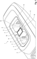
- FIG. 1 shows a console 1 which is part of a console arrangement for a vehicle.
- the console 1 is designed as a center console which is located between the front seats of a vehicle.
- the console has an outer housing 2 with a surrounding housing edge 3.
- An insert 4 is inserted into the console which is designed as a so-called cup holder 5 and has two adjacent receptacles separated by a crosspiece 6, for example for beverage containers ("cups") in the form of depressions 8, 9 with respective inner contours 10, 11.
- the cup holder 5 has a spectacle-shaped edge region 12 which surrounds the depressions 8, 9.
- Known resilient retaining lugs 13 protrude into the depressions. Designs are also conceivable in which the edge region 12 only surrounds parts of the depressions.
- a receptacle 14 is provided for an electromechanical interface 16 - also referred to as a multi-hub - which can be equipped with multifunctional functional elements.
- the interface is not in use. In this non-use state, it is not connected to a corresponding complementary interface of a functional element and is covered or closed by a closure flap 18 to protect against the ingress of liquid or other external contamination.
- FIG. 2 shows a modification of console 1 according to Figure 1 , whereby Figure 1 identical or functionally equivalent elements are provided with the same reference numerals supplemented by an apostrophe. In contrast to the design according to Figure 1 no separating strip.
- the interface 16' is arranged in a suitable receptacle 19 in the end area 20 of the console 1' in its housing edge 3'.
- the closure flap 18' is pivoted into an open position against the force of a spring (not shown). This allows a view into the interface 16, on one wall 21 of which spring-loaded electrical contacts 22 are indicated.
- FIG 3 shows the console 1 according to Figure 1 , wherein a functional element 23 in the form of a holder with an integrated charging device 24 for a mobile phone 25 (for example a so-called Qi charger) is inserted into the recess 8.
- a corresponding, complementary interface 28 is operatively connected to the interface 16.
- this mechanical connection is the only connection that prevents (vertical) removal or jumping out of the functional element when corresponding vertical forces are applied (as described below), or at least makes it more difficult.
- the functional element is in electrical and mechanical connection with the console or in contact with the Figure 3 invisible electrical contact partners (spring-loaded contacts) in operating position 30.
- the functional element 23 ensures a connection of the mobile phone 25 both with regard to data to be exchanged and, particularly preferably, with regard to the electrical charging of the mobile phone 25 or its energy storage device.
- the charging of the mobile phone 25 is particularly preferably carried out by a charging device 32 (preferably wireless inductive) which is known per se and therefore not described in detail here and which is integrated in a suitable position in the functional element 23 (see Figure 5 ).
- Figure 4 shows the arrangement of the functional element 23 with the mobile phone 25 recorded in accordance with Figure 2 designed console 1'.
- the functional element 23 cooperates as previously described with the interface 16 ', which is designed in the same way as the previously explained interface 16, but rotated by 180 degrees and arranged in the end region 20 of the console 1'.
- the display of the mobile phone 25 is also advantageously turned by 180 degrees, so that, for example, traffic regulations can be taken into account, according to which the display of the mobile phone must not be visible to the driver (while driving) while the display is visible to the front passenger can remain recognizable.
- Figure 5 shows a longitudinal section along the line VV in Figure 3 .
- the interface 16 or the connection between the interface 16 and the corresponding interface 28 is advantageously arranged in a closed multi-hub receptacle 40.
- the multi-hub receptacle 40 is at a vertical distance 43 from the bottom 42 of the recess 8 or from the bottom 42 in the area of the recess 9 at a vertical distance 44. This advantageously prevents media, in particular liquids, from inadvertently entering the recesses 8, 9 and collecting on the floor 42 from influencing or damaging the interfaces or the electrical contacts.
- the functional element 23 is formed in one piece and includes a holding or supporting part 46 for the mobile phone 25, which extends in the recess 8, and an electrical and mechanical connecting part 47, which contains the corresponding interface 28.
- the parts 46, 47 can preferably be manufactured in one piece using an injection molding process.
- the holding part 46 contains the inductive charging device 32.
- the contour of the holding part 46 is at least partially adapted to the inner contour 10 of the recess 8 in the jacket area 48 and includes the foot area 26, with which the functional element 23 rests on a support point 50 essentially in the vertical direction the bottom 42 of the recess 8 is supported.
- a second support point 53 is formed by an extension 54 of the holding part 46, with which it is supported on the edge region 12.
- the holding part 46 can be designed in the lateral direction - i.e. in the installation position transverse to the vehicle's longitudinal direction - such that it comes into contour-adapted physical contact with the inner contour 10 or its inner wall 56 of the recess 8. This results in additional stabilization of the functional element 23 in the operating position 30.
- Figure 6 section A from Figure 5 in enlarged view.
- picture 14 which is surrounded by walls, Figure 6 only the opposite walls 62, 63 are visible, and the dividing web 6 ( Figure 1 ), interface 16 (multi-hub) is used.
- Figure 6 are already in connection with Figure 2 mentioned spring-loaded contacts 22 can be seen more clearly.
- the complementary interface 28 is equipped with contacts 58 which, in the operating position 30, come into contact and thus into electrical contact with the associated contacts 22.
- the contacts 22 are connected to the vehicle's electrical system via an electrical connection 59 (not shown in detail).
- the connecting part 47 has the closure flap 18 from the in Figure 1
- the closed position shown is deflected into an open position 64 against the force of a spring, not shown, about an upper pivot axis oriented perpendicular to the plane of the drawing. This is the position in which it lies Closure flap 18 is spring-loaded on the connecting part 47.
- a shoulder 66 is provided, which, in cooperation with an edge 67 of the free end of the closure flap 18, forms a lock 69.
- a slot 72 is provided in the top 70 of the connecting part 47 facing the vehicle interior, through which a conventional credit card can be inserted, the leading edge of which deflects the closure flap 18 counterclockwise about the pivot axis to such an extent that the Edge 67 emerges behind the shoulder 66 and thus out of the vertical movement path of the section 65 when the functional element 23 is removed.
- the functional element 23 can be easily removed from the operating position 30 by pulling vertically.
- the removal movement can be supported by spring elements, such as essentially vertically acting coil springs.
- a coil spring could, for example, be in an in Figure 6 Only indicated, downwardly open pocket 74 is located and is thus supported with one end on the bottom 75 of the receiving space and with its other end in the upper region 76 of the pocket 74.
- the coil spring In the operating position of the functional element 23, the coil spring is in a compressed, i.e. prestressed, state.
- another functional element designed with a corresponding complementary interface 28 can be inserted and locked as described.
Landscapes
- Engineering & Computer Science (AREA)
- Mechanical Engineering (AREA)
- Vehicle Step Arrangements And Article Storage (AREA)
Applications Claiming Priority (1)
| Application Number | Priority Date | Filing Date | Title |
|---|---|---|---|
| DE102022210023.9A DE102022210023A1 (de) | 2022-09-22 | 2022-09-22 | Konsolenanordnung für ein Fahrzeug |
Publications (1)
| Publication Number | Publication Date |
|---|---|
| EP4344954A1 true EP4344954A1 (fr) | 2024-04-03 |
Family
ID=87762902
Family Applications (1)
| Application Number | Title | Priority Date | Filing Date |
|---|---|---|---|
| EP23192828.4A Withdrawn EP4344954A1 (fr) | 2022-09-22 | 2023-08-22 | Ensemble console pour véhicule |
Country Status (3)
| Country | Link |
|---|---|
| EP (1) | EP4344954A1 (fr) |
| CN (1) | CN117734585A (fr) |
| DE (1) | DE102022210023A1 (fr) |
Families Citing this family (1)
| Publication number | Priority date | Publication date | Assignee | Title |
|---|---|---|---|---|
| DE102023119151A1 (de) * | 2023-07-20 | 2025-01-23 | Bayerische Motoren Werke Aktiengesellschaft | Innenraumkomponente und instrumententafel für ein kraftfahrzeug |
Citations (9)
| Publication number | Priority date | Publication date | Assignee | Title |
|---|---|---|---|---|
| DE202007012617U1 (de) | 2007-09-08 | 2007-12-27 | Dr. Schneider Kunststoffwerke Gmbh | Einsatz für eine Vorrichtung zum Halten von Getränkebehältern |
| EP1946971A2 (fr) | 2007-01-17 | 2008-07-23 | Ford Global Technologies, LLC, A subsidary of Ford Motor Company | Élément de console encastré pour un véhicule |
| DE102011119424A1 (de) * | 2011-11-25 | 2013-05-29 | GM Global Technology Operations LLC (n. d. Gesetzen des Staates Delaware) | Konsolenanordnung und Kraftfahrzeug mit einer Konsolenanordnung |
| WO2013127323A1 (fr) | 2012-02-29 | 2013-09-06 | Volkswagen Ag | Console centrale, porte-objet et dispositif de séparation dans la console centrale et le porte-objet |
| DE10316817B4 (de) | 2003-04-11 | 2017-06-08 | Volkswagen Ag | Haltevorrichtung für Getränkebehälter an einem Ablagefach eines Fahrzeugs |
| DE102016102736A1 (de) * | 2016-02-17 | 2017-08-17 | Dr. Ing. H.C. F. Porsche Aktiengesellschaft | Mittelkonsole mit einem schwenkbaren Deckelelement |
| US20190092243A1 (en) * | 2017-09-28 | 2019-03-28 | Nissan North America, Inc. | Re-configurable center console assembly |
| DE102018005602B3 (de) | 2018-07-14 | 2019-10-10 | Psa Automobiles Sa | Funktionsanordnung zur Anordnung an einer Innenraumstruktur eines Fahrzeugs, Innenraumstruktur mit der Funktionsanordnung und Fahrzeug mit der Innenraumstruktur |
| DE102020126180A1 (de) * | 2020-10-07 | 2022-04-07 | Audi Aktiengesellschaft | Halte- und Bediensystem für ein mobiles Endgerät |
Family Cites Families (1)
| Publication number | Priority date | Publication date | Assignee | Title |
|---|---|---|---|---|
| US10773657B2 (en) * | 2018-11-09 | 2020-09-15 | Calsonic Kansei North America, Inc. | Removable electronic device holder |
-
2022
- 2022-09-22 DE DE102022210023.9A patent/DE102022210023A1/de not_active Withdrawn
-
2023
- 2023-08-22 EP EP23192828.4A patent/EP4344954A1/fr not_active Withdrawn
- 2023-09-15 CN CN202311200313.7A patent/CN117734585A/zh active Pending
Patent Citations (9)
| Publication number | Priority date | Publication date | Assignee | Title |
|---|---|---|---|---|
| DE10316817B4 (de) | 2003-04-11 | 2017-06-08 | Volkswagen Ag | Haltevorrichtung für Getränkebehälter an einem Ablagefach eines Fahrzeugs |
| EP1946971A2 (fr) | 2007-01-17 | 2008-07-23 | Ford Global Technologies, LLC, A subsidary of Ford Motor Company | Élément de console encastré pour un véhicule |
| DE202007012617U1 (de) | 2007-09-08 | 2007-12-27 | Dr. Schneider Kunststoffwerke Gmbh | Einsatz für eine Vorrichtung zum Halten von Getränkebehältern |
| DE102011119424A1 (de) * | 2011-11-25 | 2013-05-29 | GM Global Technology Operations LLC (n. d. Gesetzen des Staates Delaware) | Konsolenanordnung und Kraftfahrzeug mit einer Konsolenanordnung |
| WO2013127323A1 (fr) | 2012-02-29 | 2013-09-06 | Volkswagen Ag | Console centrale, porte-objet et dispositif de séparation dans la console centrale et le porte-objet |
| DE102016102736A1 (de) * | 2016-02-17 | 2017-08-17 | Dr. Ing. H.C. F. Porsche Aktiengesellschaft | Mittelkonsole mit einem schwenkbaren Deckelelement |
| US20190092243A1 (en) * | 2017-09-28 | 2019-03-28 | Nissan North America, Inc. | Re-configurable center console assembly |
| DE102018005602B3 (de) | 2018-07-14 | 2019-10-10 | Psa Automobiles Sa | Funktionsanordnung zur Anordnung an einer Innenraumstruktur eines Fahrzeugs, Innenraumstruktur mit der Funktionsanordnung und Fahrzeug mit der Innenraumstruktur |
| DE102020126180A1 (de) * | 2020-10-07 | 2022-04-07 | Audi Aktiengesellschaft | Halte- und Bediensystem für ein mobiles Endgerät |
Also Published As
| Publication number | Publication date |
|---|---|
| DE102022210023A1 (de) | 2024-03-28 |
| CN117734585A (zh) | 2024-03-22 |
Similar Documents
| Publication | Publication Date | Title |
|---|---|---|
| DE102014016434B3 (de) | Verfahren zum Betreiben einer Aufnahmevorrichtung, Aufnahmevorrichtung und Kraftwagen mit einer Aufnahmevorrichtung | |
| EP3616998B1 (fr) | Compartiment de rangement pour un habitacle d'un véhicule | |
| EP3743314B1 (fr) | Agencement de maintien d'un terminal mobile et véhicule pourvu d'un tel agencement de maintien | |
| EP1773625B1 (fr) | Systeme d'enfichage multifonctionnel | |
| WO2009112532A1 (fr) | Porte-appareil pour intégration dans un véhicule automobile | |
| EP3241706B1 (fr) | Dispositif et système de réception d'objets dans un véhicule | |
| DE102016001226A1 (de) | Fahrzeug mit einer Ablagebox für ein batteriebetriebenes Gerät, insbesondere für ein Mobiltelefon | |
| DE202007012617U1 (de) | Einsatz für eine Vorrichtung zum Halten von Getränkebehältern | |
| DE102016005734A1 (de) | Ladestation zum elektrischen Aufladen eines Mobiltelefons in einem Fahrzeug und Fahrzeug mit einer solchen Ladestation | |
| EP4344954A1 (fr) | Ensemble console pour véhicule | |
| DE102016119355B4 (de) | Ablagefach, umfassend ein faltbares Halteelement | |
| EP1181169B1 (fr) | Support pour contenant de boisson | |
| EP0748721B1 (fr) | Dispositif de logement pour appareils ou objects dans le compartiment passager d'un véhicule | |
| DE102007004446A1 (de) | Armaturenfach eines Fahrzeugs für einen mobilen Computer | |
| DE4110767C2 (fr) | ||
| DE102022102403A1 (de) | Ablagefach, insbesondere für ein Kraftfahrzeug | |
| DE102019202532B4 (de) | Ablage- und/oder Servicefach sowie Fahrzeug mit einem derartigen Ablage- und/oder Servicefach | |
| DE112018002622B4 (de) | Als Behälterhalter dienende Lüftereinheit | |
| EP1566309B1 (fr) | Boîtier de transport pour véhicule pour fixation sur dossier de siège ou paroie intérieur de coffre | |
| DE102021133777B3 (de) | Fahrzeug mit einem Verstaufach | |
| DE102018210988B4 (de) | Verkleidungselement mit Aufnahme für Warndreieck, Heckklappe mit Verkleidungselement und Kraftfahrzeug mit einer solchen Heckklappe | |
| DE102006052598B4 (de) | Abdeckvorrichtung für einen Gepäckraum eines Kraftfahrzeuges | |
| DE102024116617B3 (de) | Multifunktionale Mittelkonsole für ein Fahrzeug, sowie Fahrzeug mit einer solchen Mittelkonsole | |
| DE102005025886B4 (de) | Behälteranordnung | |
| DE102015120457A1 (de) | Armauflagevorrichtung |
Legal Events
| Date | Code | Title | Description |
|---|---|---|---|
| PUAI | Public reference made under article 153(3) epc to a published international application that has entered the european phase |
Free format text: ORIGINAL CODE: 0009012 |
|
| STAA | Information on the status of an ep patent application or granted ep patent |
Free format text: STATUS: THE APPLICATION HAS BEEN PUBLISHED |
|
| AK | Designated contracting states |
Kind code of ref document: A1 Designated state(s): AL AT BE BG CH CY CZ DE DK EE ES FI FR GB GR HR HU IE IS IT LI LT LU LV MC ME MK MT NL NO PL PT RO RS SE SI SK SM TR |
|
| STAA | Information on the status of an ep patent application or granted ep patent |
Free format text: STATUS: REQUEST FOR EXAMINATION WAS MADE |
|
| 17P | Request for examination filed |
Effective date: 20241004 |
|
| RBV | Designated contracting states (corrected) |
Designated state(s): AL AT BE BG CH CY CZ DE DK EE ES FI FR GB GR HR HU IE IS IT LI LT LU LV MC ME MK MT NL NO PL PT RO RS SE SI SK SM TR |
|
| STAA | Information on the status of an ep patent application or granted ep patent |
Free format text: STATUS: THE APPLICATION IS DEEMED TO BE WITHDRAWN |
|
| 18D | Application deemed to be withdrawn |
Effective date: 20241005 |