EP4345008A1 - Verfahren und vorrichtung zur herstellung eines wasserstofftanks, damit erhältlicher tank und flugzeug - Google Patents
Verfahren und vorrichtung zur herstellung eines wasserstofftanks, damit erhältlicher tank und flugzeug Download PDFInfo
- Publication number
- EP4345008A1 EP4345008A1 EP22198107.9A EP22198107A EP4345008A1 EP 4345008 A1 EP4345008 A1 EP 4345008A1 EP 22198107 A EP22198107 A EP 22198107A EP 4345008 A1 EP4345008 A1 EP 4345008A1
- Authority
- EP
- European Patent Office
- Prior art keywords
- hydrogen tank
- galvanic
- tank body
- hydrogen
- manufacturing
- Prior art date
- Legal status (The legal status is an assumption and is not a legal conclusion. Google has not performed a legal analysis and makes no representation as to the accuracy of the status listed.)
- Pending
Links
Images



Classifications
-
- B—PERFORMING OPERATIONS; TRANSPORTING
- B64—AIRCRAFT; AVIATION; COSMONAUTICS
- B64D—EQUIPMENT FOR FITTING IN OR TO AIRCRAFT; FLIGHT SUITS; PARACHUTES; ARRANGEMENT OR MOUNTING OF POWER PLANTS OR PROPULSION TRANSMISSIONS IN AIRCRAFT
- B64D37/00—Arrangements in connection with fuel supply for power plant
- B64D37/30—Fuel systems for specific fuels
-
- F—MECHANICAL ENGINEERING; LIGHTING; HEATING; WEAPONS; BLASTING
- F17—STORING OR DISTRIBUTING GASES OR LIQUIDS
- F17C—VESSELS FOR CONTAINING OR STORING COMPRESSED, LIQUEFIED OR SOLIDIFIED GASES; FIXED-CAPACITY GAS-HOLDERS; FILLING VESSELS WITH, OR DISCHARGING FROM VESSELS, COMPRESSED, LIQUEFIED, OR SOLIDIFIED GASES
- F17C3/00—Vessels not under pressure
- F17C3/02—Vessels not under pressure with provision for thermal insulation
- F17C3/08—Vessels not under pressure with provision for thermal insulation by vacuum spaces, e.g. Dewar flask
-
- F—MECHANICAL ENGINEERING; LIGHTING; HEATING; WEAPONS; BLASTING
- F17—STORING OR DISTRIBUTING GASES OR LIQUIDS
- F17C—VESSELS FOR CONTAINING OR STORING COMPRESSED, LIQUEFIED OR SOLIDIFIED GASES; FIXED-CAPACITY GAS-HOLDERS; FILLING VESSELS WITH, OR DISCHARGING FROM VESSELS, COMPRESSED, LIQUEFIED, OR SOLIDIFIED GASES
- F17C2201/00—Vessel construction, in particular geometry, arrangement or size
- F17C2201/01—Shape
- F17C2201/0104—Shape cylindrical
- F17C2201/0119—Shape cylindrical with flat end-piece
-
- F—MECHANICAL ENGINEERING; LIGHTING; HEATING; WEAPONS; BLASTING
- F17—STORING OR DISTRIBUTING GASES OR LIQUIDS
- F17C—VESSELS FOR CONTAINING OR STORING COMPRESSED, LIQUEFIED OR SOLIDIFIED GASES; FIXED-CAPACITY GAS-HOLDERS; FILLING VESSELS WITH, OR DISCHARGING FROM VESSELS, COMPRESSED, LIQUEFIED, OR SOLIDIFIED GASES
- F17C2203/00—Vessel construction, in particular walls or details thereof
- F17C2203/03—Thermal insulations
- F17C2203/0304—Thermal insulations by solid means
-
- F—MECHANICAL ENGINEERING; LIGHTING; HEATING; WEAPONS; BLASTING
- F17—STORING OR DISTRIBUTING GASES OR LIQUIDS
- F17C—VESSELS FOR CONTAINING OR STORING COMPRESSED, LIQUEFIED OR SOLIDIFIED GASES; FIXED-CAPACITY GAS-HOLDERS; FILLING VESSELS WITH, OR DISCHARGING FROM VESSELS, COMPRESSED, LIQUEFIED, OR SOLIDIFIED GASES
- F17C2203/00—Vessel construction, in particular walls or details thereof
- F17C2203/03—Thermal insulations
- F17C2203/0391—Thermal insulations by vacuum
-
- F—MECHANICAL ENGINEERING; LIGHTING; HEATING; WEAPONS; BLASTING
- F17—STORING OR DISTRIBUTING GASES OR LIQUIDS
- F17C—VESSELS FOR CONTAINING OR STORING COMPRESSED, LIQUEFIED OR SOLIDIFIED GASES; FIXED-CAPACITY GAS-HOLDERS; FILLING VESSELS WITH, OR DISCHARGING FROM VESSELS, COMPRESSED, LIQUEFIED, OR SOLIDIFIED GASES
- F17C2203/00—Vessel construction, in particular walls or details thereof
- F17C2203/06—Materials for walls or layers thereof; Properties or structures of walls or their materials
- F17C2203/0602—Wall structures; Special features thereof
- F17C2203/0604—Liners
-
- F—MECHANICAL ENGINEERING; LIGHTING; HEATING; WEAPONS; BLASTING
- F17—STORING OR DISTRIBUTING GASES OR LIQUIDS
- F17C—VESSELS FOR CONTAINING OR STORING COMPRESSED, LIQUEFIED OR SOLIDIFIED GASES; FIXED-CAPACITY GAS-HOLDERS; FILLING VESSELS WITH, OR DISCHARGING FROM VESSELS, COMPRESSED, LIQUEFIED, OR SOLIDIFIED GASES
- F17C2203/00—Vessel construction, in particular walls or details thereof
- F17C2203/06—Materials for walls or layers thereof; Properties or structures of walls or their materials
- F17C2203/0602—Wall structures; Special features thereof
- F17C2203/0607—Coatings
-
- F—MECHANICAL ENGINEERING; LIGHTING; HEATING; WEAPONS; BLASTING
- F17—STORING OR DISTRIBUTING GASES OR LIQUIDS
- F17C—VESSELS FOR CONTAINING OR STORING COMPRESSED, LIQUEFIED OR SOLIDIFIED GASES; FIXED-CAPACITY GAS-HOLDERS; FILLING VESSELS WITH, OR DISCHARGING FROM VESSELS, COMPRESSED, LIQUEFIED, OR SOLIDIFIED GASES
- F17C2203/00—Vessel construction, in particular walls or details thereof
- F17C2203/06—Materials for walls or layers thereof; Properties or structures of walls or their materials
- F17C2203/0602—Wall structures; Special features thereof
- F17C2203/0612—Wall structures
- F17C2203/0626—Multiple walls
- F17C2203/0629—Two walls
-
- F—MECHANICAL ENGINEERING; LIGHTING; HEATING; WEAPONS; BLASTING
- F17—STORING OR DISTRIBUTING GASES OR LIQUIDS
- F17C—VESSELS FOR CONTAINING OR STORING COMPRESSED, LIQUEFIED OR SOLIDIFIED GASES; FIXED-CAPACITY GAS-HOLDERS; FILLING VESSELS WITH, OR DISCHARGING FROM VESSELS, COMPRESSED, LIQUEFIED, OR SOLIDIFIED GASES
- F17C2203/00—Vessel construction, in particular walls or details thereof
- F17C2203/06—Materials for walls or layers thereof; Properties or structures of walls or their materials
- F17C2203/0634—Materials for walls or layers thereof
- F17C2203/0636—Metals
-
- F—MECHANICAL ENGINEERING; LIGHTING; HEATING; WEAPONS; BLASTING
- F17—STORING OR DISTRIBUTING GASES OR LIQUIDS
- F17C—VESSELS FOR CONTAINING OR STORING COMPRESSED, LIQUEFIED OR SOLIDIFIED GASES; FIXED-CAPACITY GAS-HOLDERS; FILLING VESSELS WITH, OR DISCHARGING FROM VESSELS, COMPRESSED, LIQUEFIED, OR SOLIDIFIED GASES
- F17C2203/00—Vessel construction, in particular walls or details thereof
- F17C2203/06—Materials for walls or layers thereof; Properties or structures of walls or their materials
- F17C2203/0634—Materials for walls or layers thereof
- F17C2203/0636—Metals
- F17C2203/0648—Alloys or compositions of metals
-
- F—MECHANICAL ENGINEERING; LIGHTING; HEATING; WEAPONS; BLASTING
- F17—STORING OR DISTRIBUTING GASES OR LIQUIDS
- F17C—VESSELS FOR CONTAINING OR STORING COMPRESSED, LIQUEFIED OR SOLIDIFIED GASES; FIXED-CAPACITY GAS-HOLDERS; FILLING VESSELS WITH, OR DISCHARGING FROM VESSELS, COMPRESSED, LIQUEFIED, OR SOLIDIFIED GASES
- F17C2203/00—Vessel construction, in particular walls or details thereof
- F17C2203/06—Materials for walls or layers thereof; Properties or structures of walls or their materials
- F17C2203/0634—Materials for walls or layers thereof
- F17C2203/0658—Synthetics
- F17C2203/066—Plastics
-
- F—MECHANICAL ENGINEERING; LIGHTING; HEATING; WEAPONS; BLASTING
- F17—STORING OR DISTRIBUTING GASES OR LIQUIDS
- F17C—VESSELS FOR CONTAINING OR STORING COMPRESSED, LIQUEFIED OR SOLIDIFIED GASES; FIXED-CAPACITY GAS-HOLDERS; FILLING VESSELS WITH, OR DISCHARGING FROM VESSELS, COMPRESSED, LIQUEFIED, OR SOLIDIFIED GASES
- F17C2203/00—Vessel construction, in particular walls or details thereof
- F17C2203/06—Materials for walls or layers thereof; Properties or structures of walls or their materials
- F17C2203/0634—Materials for walls or layers thereof
- F17C2203/0658—Synthetics
- F17C2203/0663—Synthetics in form of fibers or filaments
-
- F—MECHANICAL ENGINEERING; LIGHTING; HEATING; WEAPONS; BLASTING
- F17—STORING OR DISTRIBUTING GASES OR LIQUIDS
- F17C—VESSELS FOR CONTAINING OR STORING COMPRESSED, LIQUEFIED OR SOLIDIFIED GASES; FIXED-CAPACITY GAS-HOLDERS; FILLING VESSELS WITH, OR DISCHARGING FROM VESSELS, COMPRESSED, LIQUEFIED, OR SOLIDIFIED GASES
- F17C2209/00—Vessel construction, in particular methods of manufacturing
-
- F—MECHANICAL ENGINEERING; LIGHTING; HEATING; WEAPONS; BLASTING
- F17—STORING OR DISTRIBUTING GASES OR LIQUIDS
- F17C—VESSELS FOR CONTAINING OR STORING COMPRESSED, LIQUEFIED OR SOLIDIFIED GASES; FIXED-CAPACITY GAS-HOLDERS; FILLING VESSELS WITH, OR DISCHARGING FROM VESSELS, COMPRESSED, LIQUEFIED, OR SOLIDIFIED GASES
- F17C2221/00—Handled fluid, in particular type of fluid
- F17C2221/01—Pure fluids
- F17C2221/012—Hydrogen
-
- F—MECHANICAL ENGINEERING; LIGHTING; HEATING; WEAPONS; BLASTING
- F17—STORING OR DISTRIBUTING GASES OR LIQUIDS
- F17C—VESSELS FOR CONTAINING OR STORING COMPRESSED, LIQUEFIED OR SOLIDIFIED GASES; FIXED-CAPACITY GAS-HOLDERS; FILLING VESSELS WITH, OR DISCHARGING FROM VESSELS, COMPRESSED, LIQUEFIED, OR SOLIDIFIED GASES
- F17C2223/00—Handled fluid before transfer, i.e. state of fluid when stored in the vessel or before transfer from the vessel
- F17C2223/01—Handled fluid before transfer, i.e. state of fluid when stored in the vessel or before transfer from the vessel characterised by the phase
- F17C2223/0146—Two-phase
- F17C2223/0153—Liquefied gas, e.g. LPG, GPL
- F17C2223/0161—Liquefied gas, e.g. LPG, GPL cryogenic, e.g. LNG, GNL, PLNG
-
- F—MECHANICAL ENGINEERING; LIGHTING; HEATING; WEAPONS; BLASTING
- F17—STORING OR DISTRIBUTING GASES OR LIQUIDS
- F17C—VESSELS FOR CONTAINING OR STORING COMPRESSED, LIQUEFIED OR SOLIDIFIED GASES; FIXED-CAPACITY GAS-HOLDERS; FILLING VESSELS WITH, OR DISCHARGING FROM VESSELS, COMPRESSED, LIQUEFIED, OR SOLIDIFIED GASES
- F17C2223/00—Handled fluid before transfer, i.e. state of fluid when stored in the vessel or before transfer from the vessel
- F17C2223/03—Handled fluid before transfer, i.e. state of fluid when stored in the vessel or before transfer from the vessel characterised by the pressure level
- F17C2223/033—Small pressure, e.g. for liquefied gas
-
- F—MECHANICAL ENGINEERING; LIGHTING; HEATING; WEAPONS; BLASTING
- F17—STORING OR DISTRIBUTING GASES OR LIQUIDS
- F17C—VESSELS FOR CONTAINING OR STORING COMPRESSED, LIQUEFIED OR SOLIDIFIED GASES; FIXED-CAPACITY GAS-HOLDERS; FILLING VESSELS WITH, OR DISCHARGING FROM VESSELS, COMPRESSED, LIQUEFIED, OR SOLIDIFIED GASES
- F17C2260/00—Purposes of gas storage and gas handling
- F17C2260/01—Improving mechanical properties or manufacturing
- F17C2260/012—Reducing weight
-
- F—MECHANICAL ENGINEERING; LIGHTING; HEATING; WEAPONS; BLASTING
- F17—STORING OR DISTRIBUTING GASES OR LIQUIDS
- F17C—VESSELS FOR CONTAINING OR STORING COMPRESSED, LIQUEFIED OR SOLIDIFIED GASES; FIXED-CAPACITY GAS-HOLDERS; FILLING VESSELS WITH, OR DISCHARGING FROM VESSELS, COMPRESSED, LIQUEFIED, OR SOLIDIFIED GASES
- F17C2265/00—Effects achieved by gas storage or gas handling
- F17C2265/06—Fluid distribution
- F17C2265/066—Fluid distribution for feeding engines for propulsion
-
- F—MECHANICAL ENGINEERING; LIGHTING; HEATING; WEAPONS; BLASTING
- F17—STORING OR DISTRIBUTING GASES OR LIQUIDS
- F17C—VESSELS FOR CONTAINING OR STORING COMPRESSED, LIQUEFIED OR SOLIDIFIED GASES; FIXED-CAPACITY GAS-HOLDERS; FILLING VESSELS WITH, OR DISCHARGING FROM VESSELS, COMPRESSED, LIQUEFIED, OR SOLIDIFIED GASES
- F17C2270/00—Applications
- F17C2270/01—Applications for fluid transport or storage
- F17C2270/0165—Applications for fluid transport or storage on the road
- F17C2270/0168—Applications for fluid transport or storage on the road by vehicles
- F17C2270/0171—Trucks
-
- F—MECHANICAL ENGINEERING; LIGHTING; HEATING; WEAPONS; BLASTING
- F17—STORING OR DISTRIBUTING GASES OR LIQUIDS
- F17C—VESSELS FOR CONTAINING OR STORING COMPRESSED, LIQUEFIED OR SOLIDIFIED GASES; FIXED-CAPACITY GAS-HOLDERS; FILLING VESSELS WITH, OR DISCHARGING FROM VESSELS, COMPRESSED, LIQUEFIED, OR SOLIDIFIED GASES
- F17C2270/00—Applications
- F17C2270/01—Applications for fluid transport or storage
- F17C2270/0165—Applications for fluid transport or storage on the road
- F17C2270/0168—Applications for fluid transport or storage on the road by vehicles
- F17C2270/0173—Railways
-
- F—MECHANICAL ENGINEERING; LIGHTING; HEATING; WEAPONS; BLASTING
- F17—STORING OR DISTRIBUTING GASES OR LIQUIDS
- F17C—VESSELS FOR CONTAINING OR STORING COMPRESSED, LIQUEFIED OR SOLIDIFIED GASES; FIXED-CAPACITY GAS-HOLDERS; FILLING VESSELS WITH, OR DISCHARGING FROM VESSELS, COMPRESSED, LIQUEFIED, OR SOLIDIFIED GASES
- F17C2270/00—Applications
- F17C2270/01—Applications for fluid transport or storage
- F17C2270/0165—Applications for fluid transport or storage on the road
- F17C2270/0168—Applications for fluid transport or storage on the road by vehicles
- F17C2270/0178—Cars
-
- F—MECHANICAL ENGINEERING; LIGHTING; HEATING; WEAPONS; BLASTING
- F17—STORING OR DISTRIBUTING GASES OR LIQUIDS
- F17C—VESSELS FOR CONTAINING OR STORING COMPRESSED, LIQUEFIED OR SOLIDIFIED GASES; FIXED-CAPACITY GAS-HOLDERS; FILLING VESSELS WITH, OR DISCHARGING FROM VESSELS, COMPRESSED, LIQUEFIED, OR SOLIDIFIED GASES
- F17C2270/00—Applications
- F17C2270/01—Applications for fluid transport or storage
- F17C2270/0186—Applications for fluid transport or storage in the air or in space
- F17C2270/0189—Planes
Definitions
- the invention relates to a manufacturing method for manufacturing a hydrogen tank, especially a cryogenic hydrogen tank, more especially a tank for an aircraft. Further, the invention relates to a hydrogen tank obtainable with such method as well as to an aircraft equipped therewith. Further, the invention relates to a manufacturing apparatus for manufacturing the hydrogen tank.
- Cryogenic storage tanks may be used for storing liquid hydrogen, for example, for use as a fuel for driving a vehicle.
- the vehicle may be a motor vehicle such as a car, lorry or train or may be an aircraft.
- Citations [8] and [9] disclose a tank for the cryogenic storage of hydrogen and an aircraft with a tank installed therein. Liquid hydrogen stored within the tank is used as a fuel for the aircraft engine in place of carbon-based fuels such as kerosene.
- the cryogenic storage tank is typically substantially cylindrical and includes openings for allowing the tank to be filled with hydrogen as well as to supply the stored liquid hydrogen to the engine.
- Hydrogen has a very high interfuse rate; the density is so low that non-metallic material will be infused.
- An object of the invention is to reduce the weight of a H2-tank having a high capacity to retain H2 while the manufacturing process of the H2-tank is simplified.
- the invention provides a manufacturing method according to claim 1.
- a H2-tank achievable with such method, a manufacturing apparatus for conducting the method and an aircraft equipped with such a H2-tank achievable by such method are subject-matters of the further independent claims.
- the invention provides according to one aspect thereof a manufacturing method for manufacturing a hydrogen tank, comprising the steps of:
- step a) comprises: a1) providing the hydrogen tank body with an inner tank wall made from CFRP.
- step a) comprises: a2) providing the hydrogen tank body with an outer tank wall for thermal insulation, wherein a space between the inner and outer tank wall is evacuated and/or filled with thermal insulation material.
- step a) comprises: a3) providing the hydrogen tank body with a line connection communicating with the inside of the inner tank wall.
- step a) comprises: a4) cleaning, especially chemical and/or blast cleaning, of the inner surface of the inner tank wall.
- step a) comprises: a5) checking the quality of the inner surface of the inner tank wall, especially by surface inspection, more preferred optical or ultrasonic surface inspection.
- step b) comprises: b1) filling the hydrogen tank body with galvanic fluidity.
- step b) comprises: b2) conducting electroplating.
- step b) comprises: b3) moving the hydrogen tank body in order to reach the whole inner surface area of the inner tank side.
- step b) comprises: b4) applying a higher tank pressure within the hydrogen tank body compared to the environment during the galvanic process.
- step b) comprises: galvanic coating the inner side with a coating material chosen from the group consisting of metal, non-corrosive metal, titan, gold, silver, ceramic and plastic.
- the method further comprises: c) surface repressing, especially by high pressure pressing, of the coating material applied by the galvanic process.
- the method further comprises: d) cleaning of the galvanic liner layer.
- the method further comprises: e) measuring the thickness of the galvanic liner layer.
- the method further comprises: f) maintenance with regular inspections after periods of time.
- the invention provides a hydrogen tank, especially cryogenic hydrogen tank, obtainable by the method according to any of the preceding embodiments, comprising
- the hydrogen tank body comprises an inner tank wall from CFRP.
- the hydrogen tank body comprises an outer tank wall for thermal insulation, wherein a space between the inner and outer tank wall is evacuated and/or filled with thermal insulation material.
- the hydrogen tank body comprises a line connection communicating with the inside of the inner tank wall.
- the invention provides an aircraft comprising such a hydrogen tank.
- the invention provides a manufacturing apparatus for manufacturing a hydrogen tank, especially a cryogenic hydrogen tank, more especially a tank for an aircraft.
- the manufacturing apparatus is configured to conduct the manufacturing method according to any of preceding embodiments.
- the manufacturing apparatus comprises:
- the manufacturing apparatus comprises a cleaning lance for passing through a line connection of a hydrogen tank body and for cleaning the inner surface of the hydrogen tank body.
- the manufacturing apparatus comprises an inspection device for inspecting the inner surface of the hydrogen tank body.
- the means for galvanic coating comprise a filling device for filling the hydrogen tank body with a galvanic fluid.
- the means for galvanic coating comprise an electroplating device including an anode to be introduced into the galvanic fluid and an electric terminal that can be electrically connected to the surface material of the inner tank wall of the hydrogen tank body.
- electroplating devices for further details about electroplating devices, reference is made to [10] and [11].
- the means for galvanic coating comprise a moving device, especial gimbal moving device, configured to moving or rotate the hydrogen tank body such that the galvanic fluid reaches the whole inner surface area to achieve a constant thickness.
- a moving device especial gimbal moving device, configured to moving or rotate the hydrogen tank body such that the galvanic fluid reaches the whole inner surface area to achieve a constant thickness.
- the means for galvanic coating comprise a pressure applying device to apply an inner pressure in the inside of the hydrogen tank body during the galvanic process which inner pressure is higher, preferably more than 5-10 bar higher, as an outer pressure around the hydrogen tank body.
- manufacturing apparatus comprises a repressing lance for repressing the coated surface.
- manufacturing apparatus comprises a thickness measuring device for measuring the coating thickness.
- manufacturing apparatus comprises an inspection lance for optical or ultrasonic inspection of the galvanic liner layer.
- Preferred embodiments of the invention refer to a galvanic hydrogen tank liner, and the manufacturing thereof.
- a hydrogen tank having a tank wall made from non-metallic material, with a metal layer to stop or reduce the interfuse rate.
- a hydrogen tank which is made, at least partially, from CFRP, first a steel liner tank is manufactured and then CFRP fibres or prepregs are wrapped around the steel tank.
- Preferred embodiments of the invention aim to reduce the weight and simplify the manufacturing process of the tank.
- the hydrogen tank has an inner hydrogen tank made from fibre reinforced material, especially CFRP.
- the hydrogen tank preferably has an outer insulation tank, preferably with vacuum between the walls of the inner hydrogen tank and the outer insulation tank.
- the hydrogen tank preferably has a distribution line.
- the distribution line is configured for filling and/or emptying the tank.
- the distribution line is an implementation line for obtaining a surface protection.
- the liquids and equipment for conducting the galvanic process are introduced via the distribution line.
- the inner surface of a CFRP tank is chemically galvanized.
- Different coating materials are possible, preferably titan, gold, other metals, ceramics or even plastic, see [12].
- a preferred method has the following process steps:
- Fig. 1 shows an aircraft, especially an airplane 44 as an example for a vehicle 12 in which a hydrogen tank 10 is used.
- the airplane 44 has a propulsion system 46 with turbines 42 as engines 26.
- the turbines 42 are configured to burn hydrogen supplied from the hydrogen tank 10.
- the airplane 44 may be equipped with fuel cells (not shown), wherein hydrogen is supplied to the fuel cells from the hydrogen tank 10.
- the hydrogen tank 10 has, e.g., a cylindrical shape.
- the hydrogen tank 10 is configured as a cryogenic tank for storing liquid hydrogen (LH2) at cryogenic temperatures.
- At least one wall component 14 of the tank such as for example the middle cylindrical part 16 and an end cap 18 or the whole inner tank wall 58 (see
- Fig. 3 is made of fibre reinforced composite material, especially CFRP.
- the inner surface 20 is the surface having contact with the LH2.
- Fig. 2 shows a schematic block diagram of a manufacturing apparatus 50 for manufacturing the hydrogen tank 10.
- the manufacturing apparatus 50 comprises means 52 for providing, especially manufacturing, a hydrogen tank body 56 and means 54 for galvanic coating an inner side of the hydrogen tank body 56.
- the means 52 for providing the hydrogen tank body is a means for manufacturing such a hydrogen tank body and is configured for manufacturing a hydrogen tank body 56 (explained in more detail below with reference to Fig. 3 ) having an inner tank wall 58 made from fibre reinforced composite material.
- the means 54 for galvanic coating is configured to apply a galvanic coating, especially of metallic material, onto the inner surface 20, of the wall component 14 by conducting a galvanic process.
- Fig. 3 is a sectional view of the hydrogen tank 10, while Fig. 4 shows an enlarged view of the detail IV of Fig. 3 .
- the hydrogen tank 10 has an inner hydrogen tank 60 and an outer insulation tank 62.
- the inner hydrogen tank 60 comprises the inner tank wall 58.
- the inner hydrogen tank 60 is manufactured from fibre reinforced plastic material, especially CFRP, in a manner known per se.
- An inner surface 20 at the inner side of the inner tank wall 58 is equipped with the galvanic liner layer 22 of a non-corrosive metal, such as titan, gold, silver, ...
- the outer insulation tank 62 is made from any suitable material such as CFRP or metal.
- the outer insulation tank 62 encloses the inner hydrogen tank 60.
- a space 68 between the walls 58, 70 of the inner hydrogen tank 60 and the outer insulation tank 62 contains vacuum. In other embodiments (not shown), the space 68 is filled with thermally insulating material.
- the hydrogen tank 10 comprises a distribution line 72 for filling and emptying the hydrogen tank.
- the distribution line 72 communicates with the inside of the hydrogen tank 10 via a line connection 74.
- a hydrogen tank body 56 comprising the inner tank wall 58 is provided.
- the hydrogen tank body 56 is provided such that it comprises both the inner tank wall 58 and the surrounding outer wall 70 of the outer insulation tank 58.
- the inner tank wall 58 is manufactured from CFRP, and is enclosed in the outer insulation tank 58.
- the hydrogen tank body 56 may comprise all components of the hydrogen tank 10 except the galvanic liner layer 22.
- the means 54 for galvanic coating comprise a cleaning device 76 including a cleaning lance 78 which is configured to pass through the distribution line 72 or the line connection 74 and is configured to clean the inner surface 20, especially by chemical cleaning and/or blast cleaning.
- the result of the cleaning step is checked by a quality check.
- a quality check For example, an optical and/or ultrasonic surface inspection is conducted in order to check the quality of the cleaning. If necessary, the cleaning is continued until a required cleaning result is achieved.
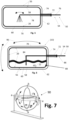
- the means 54 for galvanic coating may include an inspection lance 80 such as shown in Fig. 9 which is configured to be introduced via the line connection 74 into the interior of the hydrogen tank body 56 and is configured to conduct the surface inspection.
- the hydrogen tank body 56 is filled to a predetermined amount with a galvanic liquid 82. Further, a first electrode, such as an anode 84, of an electroplating means 86 of the means 54 for galvanic coating is introduced into the galvanic liquid 82. The inner surface 20 forms the second electrode, such as a cathode 88, of the electroplating means 86 and is connected electrically accordingly.
- the hydrogen tank body 56 is held by a moving device 90 configured to move and rotate the hydrogen tank body 56 such that the whole area of the inner surface 20 is wetted by the galvanic liquid. The moving and rotating is conducted such that a coating is electrochemically deposited thereon with a uniform thickness.
- the pressure is more than 5 to 10 bars higher as the pressure outside of the hydrogen tank body 56.
- the galvanic process is conducted under overpressure.
- the tank expansion resulting from the higher tank pressure prepares the tank stretch during later use.
- the galvanic application comprises the following steps:
- the means 54 for galvanic coating comprise a repressing lance 92 configured to be introduced into the tank interior via the line connection 74 and is configured to repress the coated material in order to form the galvanic liner layer 22.
- a cleaning step is conducted in order to clean the surface of the galvanic liner layer 22.
- the repressing can be made by applying mechanical, pneumatic or hydraulic pressure, in a static and/or vibrating way, onto the inner surface of the galvanic liner layer 22.
- the repressing is conducted such that the material of the galvanic liner layer 22 is further compacted, the surface is smoothed and/or pores are closed.
- An inspection device including the inspection lance 80 is especially configured to carry out an ultrasonic inspection in order to measure layer thickness. Additionally, an optical inspection is possible.
- the galvanic application step maybe repeated in order to increase the thickness and/or to cover a surface area which remained uncoated in the first step.
- the hydrogen tank 10 is forwarded to further steps such as installing the hydrogen tank 10 into the vehicle 12.
- the hydrogen tank 10 may be regularly inspected, such as shown in Fig. 9 , e.g., with optical means and/or ultrasonic waves. Such inspection steps may be conducted during maintenance of the vehicle 12 such as the airplane 44.
- the above-mentioned method is only a preferred embodiment, and other methods for providing the galvanic liner layer 22 on the inner surface 20 are possible.
- the galvanic application may be conducted after manufacturing of the inner tank wall 58, before it is enclosed by the outer insulation tank 62.
Landscapes
- Engineering & Computer Science (AREA)
- Aviation & Aerospace Engineering (AREA)
- Physics & Mathematics (AREA)
- Thermal Sciences (AREA)
- Mechanical Engineering (AREA)
- General Engineering & Computer Science (AREA)
- Filling Or Discharging Of Gas Storage Vessels (AREA)
Priority Applications (1)
| Application Number | Priority Date | Filing Date | Title |
|---|---|---|---|
| EP22198107.9A EP4345008A1 (de) | 2022-09-27 | 2022-09-27 | Verfahren und vorrichtung zur herstellung eines wasserstofftanks, damit erhältlicher tank und flugzeug |
Applications Claiming Priority (1)
| Application Number | Priority Date | Filing Date | Title |
|---|---|---|---|
| EP22198107.9A EP4345008A1 (de) | 2022-09-27 | 2022-09-27 | Verfahren und vorrichtung zur herstellung eines wasserstofftanks, damit erhältlicher tank und flugzeug |
Publications (1)
| Publication Number | Publication Date |
|---|---|
| EP4345008A1 true EP4345008A1 (de) | 2024-04-03 |
Family
ID=84330021
Family Applications (1)
| Application Number | Title | Priority Date | Filing Date |
|---|---|---|---|
| EP22198107.9A Pending EP4345008A1 (de) | 2022-09-27 | 2022-09-27 | Verfahren und vorrichtung zur herstellung eines wasserstofftanks, damit erhältlicher tank und flugzeug |
Country Status (1)
| Country | Link |
|---|---|
| EP (1) | EP4345008A1 (de) |
Citations (4)
| Publication number | Priority date | Publication date | Assignee | Title |
|---|---|---|---|---|
| EP1408274A2 (de) * | 2002-10-11 | 2004-04-14 | Bayerische Motoren Werke Aktiengesellschaft | Druckbehälter für kondensierte Gase, insbesondere Kryotank für ein Kraftfahrzeug |
| WO2006083274A2 (en) * | 2004-05-19 | 2006-08-10 | Egan Gregory J | Cryogenic container, superconductivity magnetic energy storage (smes) system, and method for shielding a cryogenic fluid |
| WO2020193262A1 (de) * | 2019-03-28 | 2020-10-01 | Bayerische Motoren Werke Aktiengesellschaft | Verfahren zur herstellung einer sperrschicht eines druckbehälters sowie druckbehälter |
| EP4105540A1 (de) * | 2021-06-16 | 2022-12-21 | Rolls-Royce plc | Lagerbehälter für flüssigen wasserstoff |
-
2022
- 2022-09-27 EP EP22198107.9A patent/EP4345008A1/de active Pending
Patent Citations (4)
| Publication number | Priority date | Publication date | Assignee | Title |
|---|---|---|---|---|
| EP1408274A2 (de) * | 2002-10-11 | 2004-04-14 | Bayerische Motoren Werke Aktiengesellschaft | Druckbehälter für kondensierte Gase, insbesondere Kryotank für ein Kraftfahrzeug |
| WO2006083274A2 (en) * | 2004-05-19 | 2006-08-10 | Egan Gregory J | Cryogenic container, superconductivity magnetic energy storage (smes) system, and method for shielding a cryogenic fluid |
| WO2020193262A1 (de) * | 2019-03-28 | 2020-10-01 | Bayerische Motoren Werke Aktiengesellschaft | Verfahren zur herstellung einer sperrschicht eines druckbehälters sowie druckbehälter |
| EP4105540A1 (de) * | 2021-06-16 | 2022-12-21 | Rolls-Royce plc | Lagerbehälter für flüssigen wasserstoff |
Non-Patent Citations (7)
| Title |
|---|
| "Blasenspeicher", WIKIPEDIA, 29 August 2022 (2022-08-29), Retrieved from the Internet <URL:https://de.wikipedia.org/wiki/Blasenspeicher> |
| "Electroplating", WIKIPEDIA, 29 August 2022 (2022-08-29), Retrieved from the Internet <URL:https://en.wikipedia.org/wiki/Electroplating> |
| "Elektrophoretische Abscheidung", WIKIPEDIA, 30 August 2022 (2022-08-30), Retrieved from the Internet <URL:https://de.wikipedia.org/wiki/Elektrophoretische_Abscheidung> |
| "Galvanotechnik", WIKIPEDIA, 30 August 2022 (2022-08-30), Retrieved from the Internet <URL:https://de.wikipedia.org/wiki/Galvanotechnik> |
| "Membranspeicher", WIKIPEDIA, 29 August 2022 (2022-08-29), Retrieved from the Internet <URL:https://de.wikipedia.org/wiki/Membranspeicher> |
| "Polytetrafluorethylen", WIKIPEDIA, 29 August 2022 (2022-08-29), Retrieved from the Internet <URL:https://de.wikipedia.org/wiki/Polytetrafluorethylen> |
| "Selbstdichtender Treibstofftank", WIKIPEDIA, 29 August 2022 (2022-08-29), Retrieved from the Internet <URL:https://de.wikipedia.org/wiki/Selbstdichtender_Treibstofftank> |
Similar Documents
| Publication | Publication Date | Title |
|---|---|---|
| Chen et al. | Synergistic effect of 3D current collectors and ALD surface modification for high coulombic efficiency lithium metal anodes | |
| US20120255948A1 (en) | Pressure vessel | |
| EP4345008A1 (de) | Verfahren und vorrichtung zur herstellung eines wasserstofftanks, damit erhältlicher tank und flugzeug | |
| Zhang et al. | Structure and corrosion behavior of cold-sprayed Cu/Ni composite coating post-treated by ultrasonic shot peening | |
| CN102770574A (zh) | 用于高压介质的自监测复合容器 | |
| JP2022008842A (ja) | 高圧水素ガス用蓄圧器 | |
| JP2019113121A (ja) | 高圧水素ガス用蓄圧器 | |
| KR20230023144A (ko) | 전해액 주입 장치 및 이를 이용한 이차전지의 제조방법 | |
| Xue et al. | Buckling damage of carbon fiber composite truncated cone shells under hydrostatic pressure | |
| EP4139603A1 (de) | Zusammengesetzte druckbehälter | |
| Ballinger et al. | Review and history of PSI elastomeric diaphragm tanks | |
| CN106383203A (zh) | 测量涂层弹性模量的方法 | |
| EP4286740A1 (de) | Verfahren und vorrichtung zur herstellung einer wasserstofftankwand und wandbauelement für eine solche tankwand | |
| US5143275A (en) | Method for repairing a glass layer of glass-lined equipment | |
| CN115575308B (zh) | 一种frp加固缺陷管道的电化学腐蚀装置与测试方法 | |
| CN109985744A (zh) | 冷喷涂修复系统及方法 | |
| CN118424992A (zh) | 一种检测小口径管内外壁面阻氢涂层阻氢性能的方法与装置 | |
| EP4314382A1 (de) | Verfahren zur herstellung einer permeationssperre für einen druckbehälter | |
| Martynyuk et al. | Diagnostics of Corrosion Protection Potential for Electric Water Heaters | |
| CN114152307A (zh) | 一种用于液态金属的触点式液位计及其制备方法和容器 | |
| EP3398858B1 (de) | Kraftstofftank für raumfahrzeug und herstellungsverfahren dafür | |
| CN222798683U (zh) | 固态储氢罐及车载固态储氢系统 | |
| Kakimzhanov et al. | Influence of spaying parameters on the property of detonation coatings based on Ta | |
| RU81286U1 (ru) | Емкость для хранения газов | |
| Radhika et al. | Design, Fabrication and Testing of Composite Overwrapped Pressure Vessel for CNG Storage |
Legal Events
| Date | Code | Title | Description |
|---|---|---|---|
| PUAI | Public reference made under article 153(3) epc to a published international application that has entered the european phase |
Free format text: ORIGINAL CODE: 0009012 |
|
| STAA | Information on the status of an ep patent application or granted ep patent |
Free format text: STATUS: THE APPLICATION HAS BEEN PUBLISHED |
|
| AK | Designated contracting states |
Kind code of ref document: A1 Designated state(s): AL AT BE BG CH CY CZ DE DK EE ES FI FR GB GR HR HU IE IS IT LI LT LU LV MC MK MT NL NO PL PT RO RS SE SI SK SM TR |
|
| STAA | Information on the status of an ep patent application or granted ep patent |
Free format text: STATUS: REQUEST FOR EXAMINATION WAS MADE |
|
| 17P | Request for examination filed |
Effective date: 20241004 |
|
| RBV | Designated contracting states (corrected) |
Designated state(s): AL AT BE BG CH CY CZ DE DK EE ES FI FR GB GR HR HU IE IS IT LI LT LU LV MC MK MT NL NO PL PT RO RS SE SI SK SM TR |
|
| STAA | Information on the status of an ep patent application or granted ep patent |
Free format text: STATUS: EXAMINATION IS IN PROGRESS |
|
| 17Q | First examination report despatched |
Effective date: 20250730 |