EP4345148A1 - Procédé continu de récupération de ressources secondaires à partir de déchets de films multicouches par huilage - Google Patents
Procédé continu de récupération de ressources secondaires à partir de déchets de films multicouches par huilage Download PDFInfo
- Publication number
- EP4345148A1 EP4345148A1 EP23000126.5A EP23000126A EP4345148A1 EP 4345148 A1 EP4345148 A1 EP 4345148A1 EP 23000126 A EP23000126 A EP 23000126A EP 4345148 A1 EP4345148 A1 EP 4345148A1
- Authority
- EP
- European Patent Office
- Prior art keywords
- starting material
- reactor
- continuous process
- process according
- percent
- Prior art date
- Legal status (The legal status is an assumption and is not a legal conclusion. Google has not performed a legal analysis and makes no representation as to the accuracy of the status listed.)
- Pending
Links
Images

Classifications
-
- C—CHEMISTRY; METALLURGY
- C10—PETROLEUM, GAS OR COKE INDUSTRIES; TECHNICAL GASES CONTAINING CARBON MONOXIDE; FUELS; LUBRICANTS; PEAT
- C10G—CRACKING HYDROCARBON OILS; PRODUCTION OF LIQUID HYDROCARBON MIXTURES, e.g. BY DESTRUCTIVE HYDROGENATION, OLIGOMERISATION, POLYMERISATION; RECOVERY OF HYDROCARBON OILS FROM OIL-SHALE, OIL-SAND, OR GASES; REFINING MIXTURES MAINLY CONSISTING OF HYDROCARBONS; REFORMING OF NAPHTHA; MINERAL WAXES
- C10G1/00—Production of liquid hydrocarbon mixtures from oil-shale, oil-sand, or non-melting solid carbonaceous or similar materials, e.g. wood, coal
- C10G1/10—Production of liquid hydrocarbon mixtures from oil-shale, oil-sand, or non-melting solid carbonaceous or similar materials, e.g. wood, coal from rubber or rubber waste
-
- C—CHEMISTRY; METALLURGY
- C10—PETROLEUM, GAS OR COKE INDUSTRIES; TECHNICAL GASES CONTAINING CARBON MONOXIDE; FUELS; LUBRICANTS; PEAT
- C10G—CRACKING HYDROCARBON OILS; PRODUCTION OF LIQUID HYDROCARBON MIXTURES, e.g. BY DESTRUCTIVE HYDROGENATION, OLIGOMERISATION, POLYMERISATION; RECOVERY OF HYDROCARBON OILS FROM OIL-SHALE, OIL-SAND, OR GASES; REFINING MIXTURES MAINLY CONSISTING OF HYDROCARBONS; REFORMING OF NAPHTHA; MINERAL WAXES
- C10G1/00—Production of liquid hydrocarbon mixtures from oil-shale, oil-sand, or non-melting solid carbonaceous or similar materials, e.g. wood, coal
- C10G1/02—Production of liquid hydrocarbon mixtures from oil-shale, oil-sand, or non-melting solid carbonaceous or similar materials, e.g. wood, coal by distillation
-
- C—CHEMISTRY; METALLURGY
- C10—PETROLEUM, GAS OR COKE INDUSTRIES; TECHNICAL GASES CONTAINING CARBON MONOXIDE; FUELS; LUBRICANTS; PEAT
- C10G—CRACKING HYDROCARBON OILS; PRODUCTION OF LIQUID HYDROCARBON MIXTURES, e.g. BY DESTRUCTIVE HYDROGENATION, OLIGOMERISATION, POLYMERISATION; RECOVERY OF HYDROCARBON OILS FROM OIL-SHALE, OIL-SAND, OR GASES; REFINING MIXTURES MAINLY CONSISTING OF HYDROCARBONS; REFORMING OF NAPHTHA; MINERAL WAXES
- C10G9/00—Thermal non-catalytic cracking, in the absence of hydrogen, of hydrocarbon oils
- C10G9/34—Thermal non-catalytic cracking, in the absence of hydrogen, of hydrocarbon oils by direct contact with inert preheated fluids, e.g. with molten metals or salts
- C10G9/36—Thermal non-catalytic cracking, in the absence of hydrogen, of hydrocarbon oils by direct contact with inert preheated fluids, e.g. with molten metals or salts with heated gases or vapours
-
- C—CHEMISTRY; METALLURGY
- C10—PETROLEUM, GAS OR COKE INDUSTRIES; TECHNICAL GASES CONTAINING CARBON MONOXIDE; FUELS; LUBRICANTS; PEAT
- C10G—CRACKING HYDROCARBON OILS; PRODUCTION OF LIQUID HYDROCARBON MIXTURES, e.g. BY DESTRUCTIVE HYDROGENATION, OLIGOMERISATION, POLYMERISATION; RECOVERY OF HYDROCARBON OILS FROM OIL-SHALE, OIL-SAND, OR GASES; REFINING MIXTURES MAINLY CONSISTING OF HYDROCARBONS; REFORMING OF NAPHTHA; MINERAL WAXES
- C10G2400/00—Products obtained by processes covered by groups C10G9/00 - C10G69/14
- C10G2400/02—Gasoline
-
- C—CHEMISTRY; METALLURGY
- C10—PETROLEUM, GAS OR COKE INDUSTRIES; TECHNICAL GASES CONTAINING CARBON MONOXIDE; FUELS; LUBRICANTS; PEAT
- C10G—CRACKING HYDROCARBON OILS; PRODUCTION OF LIQUID HYDROCARBON MIXTURES, e.g. BY DESTRUCTIVE HYDROGENATION, OLIGOMERISATION, POLYMERISATION; RECOVERY OF HYDROCARBON OILS FROM OIL-SHALE, OIL-SAND, OR GASES; REFINING MIXTURES MAINLY CONSISTING OF HYDROCARBONS; REFORMING OF NAPHTHA; MINERAL WAXES
- C10G2400/00—Products obtained by processes covered by groups C10G9/00 - C10G69/14
- C10G2400/04—Diesel oil
-
- C—CHEMISTRY; METALLURGY
- C10—PETROLEUM, GAS OR COKE INDUSTRIES; TECHNICAL GASES CONTAINING CARBON MONOXIDE; FUELS; LUBRICANTS; PEAT
- C10G—CRACKING HYDROCARBON OILS; PRODUCTION OF LIQUID HYDROCARBON MIXTURES, e.g. BY DESTRUCTIVE HYDROGENATION, OLIGOMERISATION, POLYMERISATION; RECOVERY OF HYDROCARBON OILS FROM OIL-SHALE, OIL-SAND, OR GASES; REFINING MIXTURES MAINLY CONSISTING OF HYDROCARBONS; REFORMING OF NAPHTHA; MINERAL WAXES
- C10G2400/00—Products obtained by processes covered by groups C10G9/00 - C10G69/14
- C10G2400/08—Jet fuel
Definitions
- the invention relates to a method for extracting secondary resources from waste multilayer films by oiling.
- the state-of-the-art technology for disposing of packaging based on multilayer films is waste incineration.
- Waste can in particular be waste that occurs in the production and/or use of multilayer films.
- Multilayer films are mainly used as packaging material, especially for food and for medical purposes.
- they are used in particular for packaging sausage, meat, cheese and dairy products.
- they are used primarily for packaging blood products, infusion solutions, liquid medicines or auxiliary solutions and in particular as sterile packaging.
- Multilayer films therefore serve a wide range of purposes in preserving food, especially sausage and cheese, as well as in packaging medicines and technical devices that require special protection.
- the main aim is to ensure the inertness of the interior space enclosed by the packaging, which means that the packaging material must be practically airtight and, in particular, must not allow oxygen to pass through.
- plastics have very different properties - some are easy to shape but permeable to air, others are airtight but mechanically less stable, and still others react with the packaged goods.
- Multilayer films are predominantly produced using the coextrusion process.
- curable masses in a solid to viscous state are continuously pressed under pressure from a shaping opening in a known manner.
- a nozzle or profile nozzle, mouthpiece, die
- a special variant is blown film extrusion.
- the melt is pressed after the extruder through a tool that is equipped in particular with an annular nozzle.
- the resulting melt tube is inflated with air and cooled by cooling air from the outside and, if necessary, also from the inside.
- the width and thickness of the film are also specified here.
- the cooled film tube is laid flat and then wound up.
- the state of the art is films with up to 11 layers that are placed on top of each other in the blow head.
- This manufacturing process is particularly suitable for plastic packaging for food, especially because these are often in demand in different sizes and shapes.
- the packaged goods are partially placed into the lower tray manually or primarily using an appropriate device and in the next step the top film is pulled from a roll directly over it and sealed.
- the bottom film is usually delivered in roll form, from which the bottom shell is formed in a deep-drawing device directly before filling. But there is also the option of pre-assembling the lower shells.
- the bottom and top films usually have different chemical compositions. Both films can also be multi-layered as required.
- Packaging films are also known in which the top film is replaced by coated paper or coated cardboard.
- the goods to be packaged are placed on a flat piece of coated paper or coated cardboard and the top film is pulled over the goods in a shrinking process, often under vacuum.
- Such packaging films are known as skin films. They adapt to any contour of the goods to be packaged, have good sealing properties and can be printed on.
- Polyethylene, polypropylene and/or polyethylene terephthalate, especially amorphous polyethylene terephthalate (APET), are often used as plastics for sealing films, especially because they are easy to seal.
- APET amorphous polyethylene terephthalate
- the object of the invention to provide a process for the material recycling of waste containing multilayer films, in particular to provide secondary resource extraction therefrom, especially for conversion into a product oil as a crude oil replacement product, which can be operated continuously and which has a uniform quality of the Product oil with regard to the maximum permissible oxygen and nitrogen content as well as the minimum calorific value of the same is guaranteed, provided that the starting material used contains waste from multilayer films in a mass proportion of at least 70%, with a mass proportion of at least 80%, preferably at least 90%, of organic compounds in the waste made of multilayer films.
- the oxygen content in the product oil should not exceed a mass fraction of 4% and the nitrogen content should not exceed a mass fraction of 1.2% and the minimum calorific value should be 41 MJ/kg.
- Oilification processes for making waste usable as a source for secondary resource extraction also known as catalytic pressureless oilification (KDV) or thermocatalytic low-temperature conversion (NTK), are known.
- KDV catalytic pressureless oilification
- NTK thermocatalytic low-temperature conversion
- the processed residual waste is fed into the lower section of the reactor by means of a screw below the liquid level. This ensures that the material fed in mixes with the oil provided and a suspension is created, which is sucked in at the lower end of the reactor via the turbines and injected back into the upper part of the reactor via pipes and connected nozzles.
- the intensive mixing breaks up the polymers and causes them to evaporate as soon as the chain length is sufficiently short.
- the vapors are drawn off at the top of the reactor and condensed using a spray cooler to obtain the product oil.
- the invention is based on known oiling processes for processing waste containing organic compounds, in particular the so-called “Dieselwest” process, which is described in the final report of the Federal Environment Agency listed above (Texts 77/2018, project number 82615, UBA-FB 002679). was presented.
- Any waste can be used as starting material, provided that it contains a mass fraction of at least 70% multilayer films, with a mass fraction of at least 80%, preferably at least 90% organic compounds, in particular polyethylene, polypropylene, polyamide 6, polyamide 6.6, polyamide 6.12, and/or polyethylene terephthalate, as well as adhesives and adhesion promoters, in particular ethylene vinyl alcohol.
- organic compounds in particular polyethylene, polypropylene, polyamide 6, polyamide 6.6, polyamide 6.12, and/or polyethylene terephthalate, as well as adhesives and adhesion promoters, in particular ethylene vinyl alcohol.
- the multilayer films can preferably be blown films, coextruded films or skin films.
- the multilayer films can also contain polyamide 6.T/6 as well as polyethylene, polypropylene, polystyrene, polylactic acid and/or polyisobutylene.
- the starting material may in particular contain silicon dioxide, aluminum oxide, ionomers, lubricants, antiblocking agents, regranulation material and/or polylactic acid, paper, in particular white paper or brown kraft paper and/or aluminum foil.
- the starting material preferably has a bulk density between 30 and 300 kilograms per cubic meter, in particular 40 to 80 kilograms per cubic meter.
- the starting material is in particular formed from predominantly flat particles, the average surface diameter of the particles of the starting material preferably being between 10 and 50 millimeters, particularly preferably between 15 and 30 millimeters.
- the average surface diameter is determined analogously to the determination of the hydraulic diameter from the ratio of four times the surface to the circumference of a particle.
- the waste from multilayer films contained in the starting material mainly comes from used packaging, in particular from food packaging, technical packaging and/or pharmaceutical packaging. It can be end-user waste and/or waste from company collection systems.
- the waste from multilayer films contained in the starting material can be production waste, processing residues, in particular trimming residues and residues from punching and/or regranulates and/or re-extrudates from the starting material (A).
- the starting material Before being fed into the reactor, the starting material is processed in a known manner, in particular as in the "Dieselwest” process described above, in several stages, i.e. crushed to a bulk density of 30 to 300 kilograms per cubic meter, preferably 60 kilograms per cubic meter, to a grain size of sieved to a maximum of 2 mm, preconditioned to an average surface diameter of the particles of the starting material, preferably between 10 and 50 millimeters, particularly preferably between 15 to 30 millimeters, ferrous and non-ferrous metals are separated, additives in the form of synthetic or natural zeolites as catalysts and quicklime as a neutralizer added and the starting material is finally dried to a water content of less than 2%.
- a start-up oil is placed in the first, lower area of the two-part reactor up to a height of at least half of the total height of the same, preferably up to a height of at least 2/3 of the total height of the same.
- the starting oil is advantageously a mixture of product oil and a mineral oil with a boiling point greater than 280 ° C, preferably in a mass ratio of 10% mineral oil to 90% product oil to 90% mineral oil to 10% product oil, in particular 50% mineral oil to 50% product oil used.
- the start-up oil is first heated to an operating temperature in the range of 280 to 420°C by pumping it through one, two or more pumps, after which the pre-prepared starting material is continuously fed into the first, lower area of the two-part reactor below the liquid level, preferably via a screw.
- the pre-prepared starting material can also be fed via an extruder.
- the oiling process is carried out in this two-part reactor, with a first, lower and a second, upper region, which is preferably directly connected to the first, lower region.
- the first, lower and/or the second, upper ones advantageously run
- the area is conical at the bottom to allow the fluid to drain away during cleaning work and standstills.
- the opening connecting the two areas has a diameter of at least 1/5 of the upper reactor diameter, preferably 1/3.
- both reactor areas can be integrated into a common reactor jacket.
- Preferred pumps are liquid ring vacuum pumps, impeller pumps with a recessed impeller, rotary piston pumps, screw spindle pumps with a high undirected impulse of at least 50%, preferably 80% of the total impulse power, the directed impulse is determined by the delivery pressure (pressure loss) and the volume flow in relation to the pump power introduced.
- the undirected impulse power is also referred to by experts as dissipated power.
- One advantage of this energy input is the homogeneous heating of the fluid from the inside to the outside, there are no hot walls as with external heating methods via the wall.
- a second major advantage of the direct dissipative energy input is the high mixing and stress on the starting material.
- the required heat of fusion is provided by the surrounding fluid.
- the pump's high mixing performance results in the solid particles introduced into the circulating flow being crushed and torn apart.
- the catalyst particles are also mixed with the introduced and melted solid particles. Due to the high shear forces and cavitation caused by peripheral speeds of 15 to 20 m/s and the sudden evaporation and condensation, the original long-chain organic compounds crack from the solid particles introduced in the liquid phase.
- the high shear rates also continuously renew the active centers of the catalysts. For example, low-pressure polyethylene waste with originally typically 2000 to 4000 monomer units is cracked to an average of 3 to 16 monomer units.
- the pumping residence time is defined by the total liquid reactor volume divided by the total pump volume flow, which is determined by mass flow meters, for example standard Coriolis meters.
- the pumping residence time is itself divided into the pumping residence time in the first, lower area of the reactor and the pumping residence time in the second, upper area of the reactor.
- the feed residence time is defined as the ratio of the total reactor volume to the feed volume flow of the feed materials.
- Preferred ratios of the pumping residence time of the reactor contents to the feed residence time of the starting material are in the range from 250 to 1 to 5000 to 1.
- the process is operated such that the pumping residence time of the reactor contents is in the range of 15 to 55 seconds, preferably in the range of 25 to 40 seconds.
- the very high ratio of the pumping residence time of the reactor contents to the feed residence time of the starting material according to the invention leads to high stress on the starting material introduced due to high shear and cavitation forces, and as a result to a higher solids conversion and to a lower oxygen and nitrogen concentration in the product oil compared to Source material.
- the reduction in the oxygen concentration is in the range of 40 to 90%, preferably 80%, and the reduction in the nitrogen concentration is in the range of 50 to 80%, preferably 70% compared to the starting material.
- the calorific value of the product oil is advantageously between 41 and 46 megajoules per kilogram, preferably around 45 megajoules per kilogram.
- polycyclic aromatic hydrocarbons in particular naphthalene, acenaphthalene, acenaphthene, fluorene, phenanthrene, anthracene, fluoranthene, pyrene and/or benzo(a)pyrene, is advantageously minimized, and the sum of the polycyclic aromatic hydrocarbons is between 100 and a maximum 1000 ppm, preferably a maximum of 600 ppm.
- Caprolactam is advantageously contained in the product oil in a concentration of 0.5 to 5 percent by weight, preferably in a concentration of at least 1.5 percent by weight.
- the surface load B of the pumped flow in the second, upper region of the two-part reactor is advantageously increased via the volume flow thereof and via the geometry of the second upper region of the two-part reactor to a value in the range of 25 m3 / m2 / h to 250 m3 / m2 / h, preferably set to a value of 100 m3/m2/h.
- the liquid pumped flow from the pumps is slightly overheated as it flows through the pumps due to the undirected energy input and is essentially expanded into the upper container due to a small pressure difference.
- the liquid jet bursts and spreads onto the existing wall surface in the second, upper area of the two-part reactor. This creates a surface. The low boilers can then escape more easily.
- the inner walls of the two-part reactor in the second, upper region thereof are partially or completely heated and/or wetted with product oil. This supports the evaporation of more volatile hydrocarbons.
- the residue from the first, lower region of the two-part reactor is advantageously discharged and allowed to settle as needed or at regular intervals and the supernatant oil mixture is returned to the first, lower region of the two-part reactor.
- the vapors are continuously withdrawn from the second, upper region of the two-part reactor and condensed in a known manner, in particular in a spray cooler, preferably in a multi-stage spray cooler, to obtain the product oil.
- the reactor contents are advantageously pumped back tangentially into the upper third of the second, upper region of the two-part reactor in order to achieve a high distribution on the wall surface of the second, upper region of the two-part reactor and thus outgassing of the products produced.
- the second, upper region of the two-part reactor can be used as a single-stage separation column by using a separable flange is provided, over which one or more horizontal perforated plates can be used.
- Perforated sheets with an opening ratio of 20 to 40% are advantageously used.
- the invention also relates to the use of the product oil obtained in a process as described above as a petroleum substitute feedstock, in particular as a substitute feedstock for naphtha and/or high vacuum gas oil in steam crackers.
- the invention also relates to the use of the product oil obtained in a process as described above as a feedstock for direct distillation for the separation of diesel fuel and/or kerosene and/or naphtha.
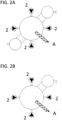
- Figure 1 shows a two-part reactor R with a first, lower area I and a second, upper area II.
- the starting material A is continuously fed via a screw conveyor into the first, lower region I of the two-part reactor R below the liquid level therein.
- the reactor contents are pumped from the first, lower region I of the reactor R into the second, upper region II of the reactor R via an external pipeline 1 using a pump 2.
- Product vapor is withdrawn from the upper end of the second, upper region II of the reactor R and quenched with a partial stream of cold product oil, obtaining the product oil P, which is withdrawn.
- the starting material (A) is provided by a manufacturer of packaging materials and is Figure 1 A total of 26.7 tons of oil with all impurities were pumped into the reactor R shown.
- the composition of the starting material (A) and that of the product oil obtained (P) are shown in Table 1.
- the pumping residence time was on average 39 s at a reactor temperature of 380 °C.
- Table 1 Source material Product oil Calorific value in megajoules per kilogram 38.18 45.4 Moisture in percent by weight 4 0.2 Inert substances in weight percent 3 0.1 (Bulk) density in kilograms per cubic meter 109 821 C (measured value) in weight percent 76.2 84.4 H (measured value) in weight percent 12.6 13.3 N (measured value) in weight percent 3.2 0.7 O (measured value) in weight percent 7.1 1.5 Polyethylene in weight percent 49.9 Polyamide in weight percent 26.1 Polyethylene terephthalate in weight percent 24.0
- the material data show a significant reduction in the nitrogen and especially the oxygen content in the product oil as well as a significant increase in the calorific value.
- a similar raw material is provided by a manufacturer of packaging materials and is used in the Figure 1
- a total of 12.2 tonnes of PET were pumped into the reactor shown with all the impurities.
- the proportion of PET in the starting material is significantly higher at around 80%.
- the composition of the starting material (A) as well as that of the obtained product oil (P) are given in Table 2.
- the pumping residence time was on average 36 s at a reactor temperature of 360 °C.
- Table 2 Source material Product oil Calorific value in megajoules per kilogram 30.2 43.29 Moisture in percent by weight 1 0.50 Inert substances in weight percent 1 0.1 (Bulk) density in kilograms per cubic meter 134 825 C (measured value) in weight percent 67.5 83.5 H (measured value) in weight percent 6.5 12.8 N (measured value) in weight percent 1.0 0.5 O (measured value) in weight percent 28.1 3.8 Polyethylene in weight percent 11.4 Polyamide in weight percent 8.1 Polyethylene terephthalate in weight percent 80.6
- the material data shows a significant reduction in the nitrogen and especially the oxygen content in the product oil as well as a significant increase in the calorific value.
Landscapes
- Chemical & Material Sciences (AREA)
- Oil, Petroleum & Natural Gas (AREA)
- Engineering & Computer Science (AREA)
- Chemical Kinetics & Catalysis (AREA)
- General Chemical & Material Sciences (AREA)
- Organic Chemistry (AREA)
- Life Sciences & Earth Sciences (AREA)
- Wood Science & Technology (AREA)
- Physics & Mathematics (AREA)
- Thermal Sciences (AREA)
- Separation, Recovery Or Treatment Of Waste Materials Containing Plastics (AREA)
- Production Of Liquid Hydrocarbon Mixture For Refining Petroleum (AREA)
Applications Claiming Priority (2)
| Application Number | Priority Date | Filing Date | Title |
|---|---|---|---|
| DE102022003577.4A DE102022003577A1 (de) | 2022-09-27 | 2022-09-27 | Kontinuierliches Verfahren zur Sekundärressourcengewinnung aus Abfällen von Mehrschichtfolien durch Verölung |
| DE102022003576.6A DE102022003576A1 (de) | 2022-09-27 | 2022-09-27 | Kontinuierliches Verfahren zur Sekundärressourcengewinnung aus organische Verbindungen enthaltenden Abfällen durch Verölung |
Publications (2)
| Publication Number | Publication Date |
|---|---|
| EP4345148A1 true EP4345148A1 (fr) | 2024-04-03 |
| EP4345148A8 EP4345148A8 (fr) | 2024-07-10 |
Family
ID=88237686
Family Applications (1)
| Application Number | Title | Priority Date | Filing Date |
|---|---|---|---|
| EP23000126.5A Pending EP4345148A1 (fr) | 2022-09-27 | 2023-09-20 | Procédé continu de récupération de ressources secondaires à partir de déchets de films multicouches par huilage |
Country Status (1)
| Country | Link |
|---|---|
| EP (1) | EP4345148A1 (fr) |
Citations (4)
| Publication number | Priority date | Publication date | Assignee | Title |
|---|---|---|---|---|
| WO2010106399A2 (fr) * | 2009-03-14 | 2010-09-23 | Bl Laboratories Sp. Z O.O. | Appareil pour réaliser la thermolyse de déchets plastiques et procédé de thermolyse en continu |
| WO2010116211A1 (fr) * | 2009-04-08 | 2010-10-14 | Bl Laboratories Sp.Z.O.O. | Appareil pour la thermolyse de déchets de matières plastiques et procédé pour la thermolyse de déchets de matières plastiques |
| US20210189252A1 (en) * | 2019-12-23 | 2021-06-24 | Chevron U.S.A. Inc. | Circular economy for plastic waste to polyethylene and lubricating oil via crude and isomerization dewaxing units |
| WO2022144627A1 (fr) * | 2020-12-28 | 2022-07-07 | Sabic Global Technologies B.V. | Procédé de traitement de déchets plastiques et d'huile de pyrolyse à partir de déchets plastiques |
-
2023
- 2023-09-20 EP EP23000126.5A patent/EP4345148A1/fr active Pending
Patent Citations (4)
| Publication number | Priority date | Publication date | Assignee | Title |
|---|---|---|---|---|
| WO2010106399A2 (fr) * | 2009-03-14 | 2010-09-23 | Bl Laboratories Sp. Z O.O. | Appareil pour réaliser la thermolyse de déchets plastiques et procédé de thermolyse en continu |
| WO2010116211A1 (fr) * | 2009-04-08 | 2010-10-14 | Bl Laboratories Sp.Z.O.O. | Appareil pour la thermolyse de déchets de matières plastiques et procédé pour la thermolyse de déchets de matières plastiques |
| US20210189252A1 (en) * | 2019-12-23 | 2021-06-24 | Chevron U.S.A. Inc. | Circular economy for plastic waste to polyethylene and lubricating oil via crude and isomerization dewaxing units |
| WO2022144627A1 (fr) * | 2020-12-28 | 2022-07-07 | Sabic Global Technologies B.V. | Procédé de traitement de déchets plastiques et d'huile de pyrolyse à partir de déchets plastiques |
Also Published As
| Publication number | Publication date |
|---|---|
| EP4345148A8 (fr) | 2024-07-10 |
Similar Documents
| Publication | Publication Date | Title |
|---|---|---|
| EP2705117B1 (fr) | Procédé pour préparer de manière énergétiquement efficace des gisements secondaires | |
| DE69213746T2 (de) | Verfahren zur aufbereitung von verbundstoffen | |
| WO2014161767A2 (fr) | Procédé de décomposition de polymères synthétiques et dispositif permettant la mise en œuvre dudit procédé | |
| EP2021116B2 (fr) | Procédé et dispositif de recyclage de matériau polyester | |
| EP0713906A1 (fr) | Procédé de recyclage de matériaux plastiques dans une unité de vapocraquage | |
| EP2598605A2 (fr) | Installation et procédé de production de carburants à partir de mélanges de biomasse et de plastique | |
| DE69807201T2 (de) | Verfahren zum entfernen von verunreinigungen aus polyestern und der kontrolle des molekulargewichtes | |
| DE102022003577A1 (de) | Kontinuierliches Verfahren zur Sekundärressourcengewinnung aus Abfällen von Mehrschichtfolien durch Verölung | |
| EP2357066A2 (fr) | Procédé et installation de fabrication de préformes de récipients | |
| WO2015194978A1 (fr) | Procédé de décomposition thermique de matières plastiques de déchets et/ou de biomasse et dispositif pour conduire le procédé | |
| WO2006015804A1 (fr) | Huilage thermique de biomasse | |
| WO2015022079A1 (fr) | Procédé et dispositif de transformation de polymères/produits de polymérisation en solution en éléments moulés en polymère | |
| EP4345148A1 (fr) | Procédé continu de récupération de ressources secondaires à partir de déchets de films multicouches par huilage | |
| DE4243063A1 (en) | Pyrolytic decomposition of plastic waste - comprises thermally decomposing waste, separating pyrolysis prod. into two fractions, recycling first fraction and recovering lighter second fraction | |
| EP0012368B1 (fr) | Procédé de fabrication de copolymères d'éthylène | |
| CH628301A5 (en) | Process for producing a plastic container for packaging goods such as foodstuffs, beverages, medicaments and cosmetics | |
| CN106745695A (zh) | 一种塔式生物滤池构建用纸蜂窝滤料 | |
| EP4345147A1 (fr) | Procédé continu de récupération de ressources secondaires à partir de déchets contenant des composés organiques par huilage | |
| EP0673963A1 (fr) | Procédé de préparation de perles de polymère expansées en continu | |
| DE2205166A1 (de) | Verfahren zur Polymerisation eines Olefins bei hohem Druck in röhrenförmigen Reaktoren | |
| DE102016105966B4 (de) | Verfahren und Anlage zum Recycling carbonfaserverstärkter Polymere | |
| DE19722586B4 (de) | Verfahren zur Gewinnung von Paraffinen und/oder Mikrowachsen aus Altkunststoffen | |
| EP1998888A1 (fr) | Dispositif de deshalogenation thermique de materiaux contenant des halogenes | |
| DE2829470A1 (de) | Verfahren zum reinigen von kreislaufgasen von kondensierten polymerteilchen | |
| EP3489330A1 (fr) | Procédé et installation permettant d'obtenir des composés aromatiques polymérisables |
Legal Events
| Date | Code | Title | Description |
|---|---|---|---|
| PUAI | Public reference made under article 153(3) epc to a published international application that has entered the european phase |
Free format text: ORIGINAL CODE: 0009012 |
|
| STAA | Information on the status of an ep patent application or granted ep patent |
Free format text: STATUS: THE APPLICATION HAS BEEN PUBLISHED |
|
| AK | Designated contracting states |
Kind code of ref document: A1 Designated state(s): AL AT BE BG CH CY CZ DE DK EE ES FI FR GB GR HR HU IE IS IT LI LT LU LV MC ME MK MT NL NO PL PT RO RS SE SI SK SM TR |
|
| RIN1 | Information on inventor provided before grant (corrected) |
Inventor name: KARPENSKY, NICOLE Inventor name: AMMICHT, ALEXANDRA Inventor name: GROTE, ULRICH Inventor name: INHOFF, OLIVIER Inventor name: BURGSTAHLER, RALF Inventor name: OLBERT, GERHARD Inventor name: ASCHAUER, STEPHAN |
|
| STAA | Information on the status of an ep patent application or granted ep patent |
Free format text: STATUS: REQUEST FOR EXAMINATION WAS MADE |
|
| 17P | Request for examination filed |
Effective date: 20240930 |
|
| RBV | Designated contracting states (corrected) |
Designated state(s): AL AT BE BG CH CY CZ DE DK EE ES FI FR GB GR HR HU IE IS IT LI LT LU LV MC ME MK MT NL NO PL PT RO RS SE SI SK SM TR |
|
| STAA | Information on the status of an ep patent application or granted ep patent |
Free format text: STATUS: EXAMINATION IS IN PROGRESS |
|
| 17Q | First examination report despatched |
Effective date: 20250626 |