EP4345232A1 - Gâche, serrure de porte et dispositif de fermeture - Google Patents
Gâche, serrure de porte et dispositif de fermeture Download PDFInfo
- Publication number
- EP4345232A1 EP4345232A1 EP23196437.0A EP23196437A EP4345232A1 EP 4345232 A1 EP4345232 A1 EP 4345232A1 EP 23196437 A EP23196437 A EP 23196437A EP 4345232 A1 EP4345232 A1 EP 4345232A1
- Authority
- EP
- European Patent Office
- Prior art keywords
- lock
- locking
- latch
- door
- exit dimension
- Prior art date
- Legal status (The legal status is an assumption and is not a legal conclusion. Google has not performed a legal analysis and makes no representation as to the accuracy of the status listed.)
- Pending
Links
Images

Classifications
-
- E—FIXED CONSTRUCTIONS
- E05—LOCKS; KEYS; WINDOW OR DOOR FITTINGS; SAFES
- E05B—LOCKS; ACCESSORIES THEREFOR; HANDCUFFS
- E05B15/00—Other details of locks; Parts for engagement by bolts of fastening devices
- E05B15/02—Striking-plates; Keepers; Bolt staples; Escutcheons
- E05B15/0205—Striking-plates, keepers, staples
- E05B15/022—Striking-plates, keepers, staples movable, resilient or yieldable
-
- E—FIXED CONSTRUCTIONS
- E05—LOCKS; KEYS; WINDOW OR DOOR FITTINGS; SAFES
- E05B—LOCKS; ACCESSORIES THEREFOR; HANDCUFFS
- E05B63/00—Locks or fastenings with special structural characteristics
- E05B63/0065—Operating modes; Transformable to different operating modes
-
- E—FIXED CONSTRUCTIONS
- E05—LOCKS; KEYS; WINDOW OR DOOR FITTINGS; SAFES
- E05B—LOCKS; ACCESSORIES THEREFOR; HANDCUFFS
- E05B63/00—Locks or fastenings with special structural characteristics
- E05B63/06—Locks or fastenings with special structural characteristics with lengthwise-adjustable bolts ; with adjustable backset, i.e. distance from door edge
-
- E—FIXED CONSTRUCTIONS
- E05—LOCKS; KEYS; WINDOW OR DOOR FITTINGS; SAFES
- E05B—LOCKS; ACCESSORIES THEREFOR; HANDCUFFS
- E05B63/00—Locks or fastenings with special structural characteristics
- E05B63/22—Locks or fastenings with special structural characteristics operated by a pulling or pushing action perpendicular to the front plate, i.e. by pulling or pushing the wing itself
-
- E—FIXED CONSTRUCTIONS
- E05—LOCKS; KEYS; WINDOW OR DOOR FITTINGS; SAFES
- E05B—LOCKS; ACCESSORIES THEREFOR; HANDCUFFS
- E05B63/00—Locks or fastenings with special structural characteristics
- E05B63/24—Arrangements in which the fastening members which engage one another are mounted respectively on the wing and the frame and are both movable, e.g. for release by moving either of them
-
- E—FIXED CONSTRUCTIONS
- E05—LOCKS; KEYS; WINDOW OR DOOR FITTINGS; SAFES
- E05C—BOLTS OR FASTENING DEVICES FOR WINGS, SPECIALLY FOR DOORS OR WINDOWS
- E05C19/00—Other devices specially designed for securing wings, e.g. with suction cups
- E05C19/02—Automatic catches, i.e. released by pull or pressure on the wing
Definitions
- the invention relates to a locking part (or locking piece) for a door lock, such a locking part z. B. is mounted on a door frame.
- the invention also relates to a door lock, in particular for a building door, wherein the door lock (which can be fastened, for example, to a door leaf or door panel) has a lock housing and a latch (latch latch) which is slidably guided in the lock housing, wherein the latch projects out of the lock housing (and possibly over a lock faceplate) by a (predefined and optionally adjustable) exit dimension when subjected to force (e.g. by spring force) and, when the door or door leaf is in the closed position, engages in a latch receptacle of a locking part which can be mounted (on a door frame) and can be pushed back into the lock housing against the application of force.
- the door lock which can be fastened, for example, to a door leaf or door panel
- the latch has a lock housing and a latch (latch latch) which is slidably guided in the lock housing, wherein the latch projects out of the lock housing (and possibly over a lock faceplate) by a (predefined and optional
- the invention further relates to a locking device for a door, in particular for a building door, which has the wing-side door lock on the one hand and the frame-side locking part on the other hand.
- the (mounted) door lock on the leaf side always works together with the locking part on the frame side, with at least one lock latch engaging in the locking part.
- the door lock usually has at least one locking element, e.g. a bolt, which - unlike a latch - cannot simply be pushed back against the force of a spring, but serves to lock the door so that a locking element is secured against being pushed back.
- the door lock can be a so-called mortise lock, which only has a single lock housing with a latch and possibly a bolt and, for. B. can be operated by a handle and/or key operated.
- the door lock is preferably a multiple locking system which, on the one hand, has a central lock (with a latch and optionally a bolt as a locking element) and one or more additional locks, each of which has at least one (additional) locking element.
- the additional locks are usually coupled to the center lock via drive rods, so that the multiple locking system is also referred to as a drive rod lock.
- the door lock is particularly preferably an automatic lock and therefore a self-locking lock, e.g. a self-locking multiple lock, in which one or more locking elements automatically extend or are extended into the locking position when the door leaf is in the closed position.
- the automatic function or self-locking can be triggered by mechanical means or magnetically in an automatic lock by mechanically or magnetically triggering a locking mechanism so that the locking elements are extended as soon as the door leaf reaches its closed position in the door frame.
- the locking elements within the additional locking devices can be designed as bolt bolts, swivel bolts or swivel hook bolts and/or latch bolts.
- Automatic locks and in particular multiple locks with an automatic function are characterized by a high degree of security, since when the door is closed, not only does the lock latch engage in the locking part on the frame, but the locking elements are also automatically extended at the same time, so that the door cannot be easily opened from the outside without authorization.
- Automatic locks of this type are, for example, from the EN 10 2008 011 551 B4 and the EN 10 2017 105 125 A1 known.
- the locking device on the locking part is also equipped with a so-called "catch function".
- the locking part has a movable, spring-loaded catch part, which z. B. can be locked using a small lever. If the catch function on the locking part is activated using this lever, the door can be pushed open from the outside even if the lock latch is retracted into the locking part, as the lock latch can push back the spring-loaded catch part when the door is pushed open.
- This function which is also known as the day trap function or catch function, allows e.g. B. to briefly leave the house via the front door and close the front door without subsequently requiring a key to enter.
- the automatic function of the lock In order to activate these day latch functions on an automatic lock, the automatic function of the lock must generally be deactivated in order to prevent self-locking and the catch function on the locking part must be set. This has basically proven itself in the locking devices known from practice, even if z. B. on the one hand a lever on the locking part and on the other hand a lever on the lock or lock faceplate must be operated.
- an automatic lock which interacts with a counter-locking part on the frame side, which is equipped with a catch function which is blocked or released via an adjusting element
- the automatic function is triggered by a control element, which can be a magnet mounted on the frame side, whereby a button in the door lock is triggered via the magnet.
- a control element which can be a magnet mounted on the frame side, whereby a button in the door lock is triggered via the magnet.
- the magnet is arranged so that it can be moved in the locking part, so that by operating an adjusting element on the lock, the latch function can be activated on the one hand and the magnet can be moved on the other.
- switching between the day function and the night function takes place by operating an adjusting element exclusively on the locking part.
- this requires the special design with a release magnet arranged so that it can be moved on the locking part, so that use is limited to certain versions.
- Multi-point locking systems with the option of switching between a night function and a day function are used, for example, in the EP 3 051 045 B1 , EP 2 151 536 B1 and the EP 2 562 335 B1 described.
- the invention is based on the object of creating a locking device or components of a locking device (in particular a locking part and/or a door lock) which are characterized by a particularly simple operation and in particular a particularly simple activation and deactivation enable a catch function for an automatic lock.
- a locking part for a door lock which has a base body on which a fixed part with a (fixed) immovable locking surface for a latch (latch locking surface) of a door lock is arranged.
- a catch part is movably arranged or movably attached to the base body, which, however, is expressly designed and dimensioned and in particular adapted to the fixed part so that the catch part with its front catch edge protrudes above the (latch) locking surface by a predetermined amount and thus a movable catch surface defined.
- the catch part preferably cannot be locked relative to the fixed part and is therefore permanently movable, i.e. H.
- a locking part is realized with a permanently movable catch part, which is always movable and can therefore be pushed back regardless of the operation of a frame-side lever.
- the movable catch surface protrudes beyond the fixed latch blocking surface in such a way that, in the closed position of the door, the latch of the lock with a first exit dimension engages behind the immovable fixed part or the latch blocking surface of the fixed part and that the latch with a reduced, second exit dimension only engages behind the movable catch part or its movable catch surface without engaging behind the blocking surface of the fixed part.
- the locking part according to the invention is therefore Particularly preferably designed for a door lock in which the exit dimension of the latch can be varied very easily by switching (on the lock), so that the latch either engages with a large immersion depth into the locking part so far that the latch engages behind the immovable latch locking surface, or with a reduced immersion depth only engages with the locking part so far that only the movable catch part is engaged behind.
- a door lock of the type described at the outset in which the exit dimension of the latch can be switched between a first exit dimension and a second exit dimension using an operating element arranged on the lock housing (and operable from the outside), the second exit dimension being smaller (by a difference) than the first exit dimension.
- the first exit dimension therefore defines a locking position in which the latch protrudes from the lock housing and, for example, over a lock faceplate in such a way that the latch, in the closed position of the door, engages behind the immovable fixed part or the immovable locking surface of the fixed part on the locking part
- the second exit dimension defines a passage position or latch position in which the latch (only) protrudes from the lock housing and, for example, over a lock faceplate in such a way that the latch, in the closed position of the door, only engages behind the movable latch part without engaging behind the fixed part.
- a locking part with a permanently movable catch part is therefore provided - preferably in combination with a door lock - so that no switching and consequently no operation is required on the frame side to switch between day function and night function or to adjust the catch function.
- the catch element on the locking part is therefore permanently active.
- the catch function can preferably be moved on the lock side and consequently on the leaf side. by means of an operating element which is arranged on the lock housing and is particularly preferably accessible and operable from the faceplate side, e.g. through an opening in the faceplate.
- the invention can therefore be particularly preferably implemented in a door lock which is designed as a self-locking automatic lock and in which the automatic function, i.e. the automatic extension of the locking elements, can be deactivated by actuating an operating element arranged on the lock housing.
- the automatic function i.e. the automatic extension of the locking elements
- both the exit dimension of the latch on the one hand and the automatic function of the lock on the other hand can now be activated or deactivated and consequently switched using the same operating element, e.g.
- the catch part of the locking part is preferably pivotably or slidably attached to the base body and/or acted upon by a catch spring.
- a catch spring Such a design is known in principle from the prior art.
- this catch part is combined with the fixed part essential to the invention, which additionally Provides a blocking surface for the latch.
- the latch blocking surface of the fixed part is preferably perpendicular to a striker bar base plane or striker bar front surface and preferably also perpendicular to the closing direction of the door and consequently perpendicular to the direction of movement in which the door leaf and thus also the lock move towards the door frame and thus towards the striker bar.
- the trap blocking surface can have a height of at least 1 mm, preferably at least 2 mm. It must be ensured that the latch locking surface is adequately gripped even in the event of dimensional deviations from the (basically predefined) first exit dimension of the lock latch in order to ensure a reliable locking effect.
- the catch edge of the catch part preferably projects beyond the fixed part or beyond the locking surface by a distance of at least 2 mm, so that a (movable) catch surface with a height of at least 2 mm is formed.
- the fixed part can have an inclined and/or arcuate sliding surface adjoining the locking surface on the top side, with only the sliding surface and not the locking surface of the fixed part being engaged behind in the passage position of the latch.
- the fixed part can have a recess in which the catch part is movably arranged, the recess dividing the locking surface and optionally the sliding surface into two spaced locking surface sections or sliding surface sections.
- the latch In this position, the latch also engages behind part of the fixed part, but only the area of the sliding surface and not the area of the blocking surface Fixed part, so that the door can be easily pushed open by, on the one hand, pivoting the catch surface against the spring force and, on the other hand, the latch slides along the sloping or arcuate sliding surface and is pushed back into the lock housing to the required extent.
- the locking part (locking piece) according to the invention is also preferably attached to the back of a locking strip, which is mounted on a door frame, for example.
- the locking part is therefore a separately manufactured one-piece or preferably multi-piece part that can be mounted on a commercially available locking strip, for example in an opening in a locking strip.
- the locking part is preferably attached to the locking part with its base body, e.g. screwed to the locking part, with at least one spacer plate in between. This allows adaptation to different locking part variants and chamber size variants, so that the same locking part and the same locking strip can be adapted to different circumstances by using one or more different spacer plates.
- the door lock is of particular importance, which enables the latch projection to be varied and thus the setting of a catch function by simply switching.
- a control element is provided on the lock, with which both the catch function and consequently the latch exit dimension can be switched and the automatic function can be deactivated or activated.
- the control element is preferably a manually operated switch, e.g. B. a slide switch or a pivot switch or a pushbutton switch, the switch being arranged on the lock housing.
- the control element is designed and positioned in such a way that it is in a state mounted on a door leaf Door lock can be operated. This can be done e.g.
- the change in the latch exit dimension does not therefore mean a setting or adjustment of a latch exit dimension in the course of assembling or adjusting a lock using a tool, but rather, according to the invention, a simple (and preferably binary) change in the exit dimension is implemented by an operating switch, which can be carried out by a person without Tools and without specialist knowledge can be done when the lock is installed in a door.
- the lock according to the invention is - as already mentioned - preferably designed as a multiple locking device, e.g. a drive rod lock.
- the inventive design of the latch or the latch mechanism and the switch preferably relates to the center lock of such a multiple locking device, ie the operating element is arranged on the center lock or in the area of the center lock, so that the operating element is used to select between the different functional positions of the center latch.
- the drive rod lock is preferably designed as an automatic lock. At least the additional locking devices are self-locking, e.g. by implementing a magnetic self-triggering mechanism on the additional locking devices.
- additional locking devices can be used which are in the EN 10 2008 011 551 B4 or the EN 10 2017 105 125 A1
- additional locking devices with mechanical release are also possible and the release for the automatic function can be provided not only on the additional locking devices themselves, but (alternatively) also on the center lock.
- the center lock also preferably has a locking element, e.g. a center bolt.
- the automatic function can, however, be limited to the additional locking devices.
- the center lock also locks automatically when the door is closed, so that the center bolt is also extended.
- a lock chain can be arranged in a basically known manner, i.e. a longitudinally displaceable element, wherein the lock chain can be displaced via a door handle and/or a locking cylinder and/or a drive (e.g. an electric motor drive) to retract one or more or all of the locking elements (and if necessary the latch).
- a drive e.g. an electric motor drive
- the lock chain can be blocked in a blocking position or released in return.
- the entire lock can first be unlocked via a door handle or the locking cylinder or a motor drive, i.e.
- the A lock nut that can be operated by a locking cylinder works on the lock chain via a change lever.
- This change lever is kinematically coupled to the lock chain, for example by a projection of the lock chain engaging in a recess on the change lever.
- this recess on the change lever can be designed as an elongated hole, so that the projection of the lock chain, e.g. a cylindrical pin, engages in the elongated hole with a movement play.
- This engagement is designed according to the invention in such a way that after the latch is retracted, it then protrudes completely by the first exit dimension or only partially by the second exit dimension from the lock housing or over the lock faceplate, depending on the position of the operating element.
- This coupling is explained in detail in the figure description by way of example.
- the second exit dimension is smaller than the first exit dimension, preferably at least 10%, e.g. B. by at least 20%, particularly preferably by at least 40%.
- the second exit dimension can thus be at least 2 mm, preferably at least 4 mm, particularly preferably at least 5 mm smaller than the first exit dimension.
- the first exit dimension can e.g. B. 6 mm to 14 mm, preferably 8 mm to 12 mm, e.g. B. be about 10 mm.
- the second exit dimension can z. B. 2 mm to 8 mm, preferably 4 mm to 6 mm, e.g. B. be about 5 mm.
- the second exit dimension is always smaller than the first exit dimension.
- the invention therefore also relates to a locking device for a door, in particular a building door, with a door lock of the type described which can be attached or attached to the door leaf and one on a door frame attachable or attached locking part of the type described.
- the new development described is characterized by a new type of latch or catch locking part, particularly for the middle lock latch of a multiple locking system.
- a lock e.g. a center lock
- the new locking part can be easily combined with commercially available locking strips. It has a fixed part housing with a straight locking surface for the middle lock latch, a molded latch slide, and a pivoting, spring-loaded catch element. The catch element is always active. It is therefore no longer switched by hand. This is possible because the depth of the centre lock latch, which can be influenced on the lock side, is used to decide whether the fully extended centre lock latch can move behind the fixed part (i.e.
- the normal locking part locking function and the door can therefore only be opened via the normal position using the handle/profile cylinder) or whether the centre lock latch only extends by around 50%, so that it does not move behind the fixed part, but only behind the flexible latch part and consequently the latch function is switched on, so that the door leaf is held in the closed position, but can be swung open at any time from the outside and inside with slightly increased hand force and can also be moved back into the latch holding position.
- the latch function can be activated and deactivated with a single movement of the hand, namely on the lock.
- the extension depth of the center lock latch is controlled by an operating lever, whereby an existing slide switch on a basically known automatic center lock can be used.
- this slide switch not only deactivates or activates the automatic function, but also manipulates or switches the extension depth of the center lock latch.
- Another advantage is, for example, automatic locks with a motor-driven unlocking system, where the locking elements can be retracted using a drive. If such a lock is unlocked using a motor, the center lock latch would only be retracted into the catch area by about 50%, so that the door would not accidentally spring open if it were opened incorrectly and the lock could then return to the locked position. However, the center lock latch would always be retracted 100% using the handle and profile cylinder.
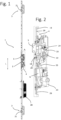
- the figures show, on the one hand, a door lock 1 attached or attachable to a door leaf F ( Fig. 1 to 5 ) and on the other hand a locking part 7 attached or attachable to a door frame R ( Fig. 6 to 9 ).
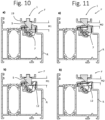
- the Fig. 10 and 11 show the inventive interaction of the door lock 1 on the one hand and the locking part 7 on the other hand.
- the door lock 1 is designed as a multiple locking device, in the embodiment as an espagnolette lock (cf. Fig. 1 )
- the espagnolette lock has a central center lock 2 and two additional locks 3.
- the center lock 2 and the additional locks 3 are attached to the back of a lock forend 19, which, together with the other components, is attached to a (in Fig. 1 (not shown) door leaf F is attached.
- the additional locks 3 are connected to the center lock via drive rods 29, which are slidably guided behind the lock faceplate 19.
- the espagnolette lock 1 can be equipped with a drive, e.g. B. be equipped with a motor drive 28, via which the drive rods (e.g. to unlock the lock) can be moved.
- the center lock usually has a lock latch or latch 5 and a latch 6 as a locking element.
- the additional locks 3 each have at least one additional bolt 21 as locking elements, which in the exemplary embodiment can be designed as a latch bolt. In principle, other configurations of the additional locks 3 or secondary locks are also possible.
- the bolt 6 and the additional locks 21 as well as the latch 5 can be retracted by operating a handle (not shown) via the lock nut 22 and/or by operating the key via the profile cylinder 23 and/or via the motor drive 28 and consequently unlock the lock and thus the door open.
- the drive rods 29 are moved upwards in the longitudinal direction L and the additional bars 21 are also retracted.
- the door lock 1 is designed as an automatic lock and thus as a self-locking lock, ie the locking elements (additional bolt 21 and/or bolt 6) are automatically extended into the locking position as soon as the door leaf F reaches the closed position and consequently the area of the door frame R.
- This automatic function can be released mechanically (e.g. via a button) or preferably magnetically via a release magnet. Details are not shown in the figures. For example, reference can be made to the EN 10 2008 011 551 B4 and EN 10 2017 105 125 A1 described solutions can be used. The structure and function of the door lock 1 according to the invention will be discussed in more detail below.
- the door lock 1 interacts with a locking part 7 attached to the door frame R, which is in the Fig. 6 to 9 is shown.
- a locking strip 8 is attached to the frame R in a known manner, which, in particular in the area of the center lock 2, has on the one hand a receptacle 30 for the bolt 6 of the center lock and, on the other hand, a receptacle for the latch 5 of the center lock.
- the locking part 7 is fastened to the locking strip 8, namely in an opening in the locking strip, as a receptacle for the latch 5.
- additional locking strips and/or locking parts for the additional locks 3 are attached to the door frame R, but these are not shown in the figures because they are known from the prior art. The invention is explained using the example of the locking part 7 for the latch 5 of the center lock.
- the locking part 7 comprises a base body 9 on the one hand and a catch part 10 on the other hand, the catch part 10 being mounted on the base body 9 so that it can move, namely pivot about an axis X.
- Locking parts with a pivotable catch part are generally known from the prior art. However, in the prior art, the movable catch part can be locked using a switch, so that the locking part can be switched between a blocking position and a through position using the switch. In the illustrated embodiment of the design according to the invention, however, such a switch on the locking part 7 is expressly dispensed with, i.e. the catch part 10 cannot be locked relative to the base body 9 and is therefore permanently movable.
- the base body 9 as a fixed part has a fixed and consequently immovable locking surface 12 for the lock latch 5 of the center lock 2.
- the latch part 10 which is movably mounted on the base body, has a front latch edge 11 which protrudes by a predetermined dimension M (e.g. 2 mm or more) over the immovable latch locking surface and thus forms a permanently movable latch surface 16.
- Whether the door or the door lock or center lock 2 is in a locked position or in a through position or latch position, in which the door can be pushed open from the outside with relatively little force, does not depend in the solution according to the invention on a switch on the frame-side locking part 7, but on the latch projection or the depth of the lock latch 5 in the locking part 7.
- the switch between a locked position on the one hand and a through position or latch position on the other hand is therefore carried out in the solution according to the invention by switching on the leaf-side door lock and in particular on the center lock 2.
- the lock latch 5 is subjected to force in a basically known manner, e.g. by spring force (a latch spring 13), so that it is always pushed forwards out of the lock housing 4 and beyond the lock face 19.
- the exit dimension of the latch 5 can be switched between a first exit dimension M1 and a second exit dimension M2 using an operating element 18 arranged on the lock housing 4, the second exit dimension M2 being smaller than the first exit dimension M1.
- the first exit dimension M1 can be, for example, approximately 10 mm
- the second exit dimension M2 is, for example, only approximately 5 mm.
- the first exit dimension M1 defines a locking position in which the latch protrudes far enough from the lock housing 4 that the latch 5 engages behind the locking surface 12 of the immovable fixed part 14 when the door is in the closed position. The door is then in the locking position so that it cannot be pushed open from the outside.
- a through position or latch position is realized according to the invention by actuating the lock-side operating element 18. This reduces the exit dimension of the latch 5 and consequently sets the second exit dimension M2, so that the lock latch 5 can only protrude beyond the lock face 19 by the second exit dimension M2.
- This second exit dimension M2 consequently defines a through position or latch position in which the lock latch 5 only protrudes from the lock housing 4 or beyond the lock face 19 so far that the latch 5 only engages behind the movable latch part 10, namely the latch surface 16, in the closed position of the door, but without engaging behind the locking surface 12 on the fixed part 14. In this position, the door can therefore be pushed open, since the lock latch 5 does not engage behind the locking surface 12, but only behind the movable latch surface 16, and the latch part 10 can thus pivot against the spring force.
- the fixed part 14 and consequently the base body 9 has an oblique or curved sliding surface 17 which adjoins the blocking surface 12 on the top, so that the latch 5 in the passage position in the area of the fixed part 14 only engages behind this sliding surface 17, but not the blocking surface 12.
- the latch In the passage position, the latch is consequently pressed against the movable catch part 10 and pivots it, and the latch slides along the curved sliding surface 17.
- the design provides that the fixed part 14 has a recess 15 in which the catch part 10 is movably arranged, this recess 15 dividing the blocking surface 12 and possibly also the sliding surface 17 into two spaced sections, ie blocking surface sections 12a and sliding surface sections 17a.
- a comparative consideration of the Fig. 8 and 9 shows in Furthermore, the base body 9 of the locking part 7 is attached to the back of the locking bar 8 with the interposition of a spacer plate 31. By selecting or replacing this spacer plate 31, an adjustment or adaptation to different conditions can be achieved during assembly.
- FIG. 10 A, B show the latch in the setting with the first exit dimension M1 and consequently in the basic blocking position.
- Fig. 11 A, B the latch 5 in the catch position with the reduced exit dimension M2.
- Fig. 10B or 11B the arrangement with the catch part hidden in order to better illustrate the interaction of the latch 5 with the locking surface 12.
- the center lock 2 is provided with an operating element 18, namely a switch 18, which protrudes from the lock housing 4 and in the embodiment shown can be actuated through an opening 20 in the lock face 19.
- This switch 18 serves, first of all, in a basically known manner to deactivate the automatic function of the door lock 1.
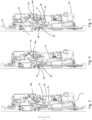
- the lock chain 24 can be released within the lock housing 4, for example by actuating the handle (not shown). over the lock nut 22 in the longitudinal direction L, and move it upwards so that the lock latch 5 is retracted.
- the lock latch thus comes out of the Fig.2 shown position with first exit dimension M1 to the fully retracted position according to Fig.3
- the lock latch can also be retracted by operating the profile cylinder 23 with the interposition of the change lever 25, since the change lever 25 also works on the lock chain 24, so that the Fig.4
- the functional position shown is reached, in which the latch is also completely retracted.
- the additional locking devices or additional bolts 21 are then also retracted via the drive rods 29.
- the switch 18 In the functional position according to Fig. 3 or Fig. 4 the switch 18 is now activated and consequently moved (transversely to the longitudinal direction L).
- the switch thus engages under a blocking extension 32 on the lock chain 24, ie the lock chain 24 is moved according to Fig.5 in the blocking position is blocked against lowering, so that the additional locking devices 21 (not shown) cannot extend, even when the door leaf F is closed.
- the automatic function is in this Fig.5 shown position is consequently blocked.
- This blocking and subsequent deactivation of the automatic function via switch 18 is basically known from the prior art.
- the switch 18 not only blocks the automatic function, but also manipulates the exit dimension of the lock latch 5 and thus switches between the functional positions M1 and M2.
- Fig.5 indicated that the lock latch 5 in this functional position of the operating switch 18 cannot extend completely by the dimension M1 due to the coupling with the latch lever 33, but only by the dimension M2.
- the door lock is therefore in the latch position in which the lock latch can only extend by the dimension M2 of e.g. 5 mm beyond the lock face 19.
- This functional position according to Fig.5 then corresponds to the Fig. 11A and 11B
- the coupling between the change lever 25 and the chain 24 is made via the slot 26 in the change lever 23 and the projection 27 on the chain 24.
- the slot 26 is dimensioned in relation to the projection 27 so that the lever 25 can be Fig.5 only sinks so far that the latch is limited to the exit dimension M2, with the aid of the latch lever 33, which is blocked by the change lever 25 via a projection 33a.
Landscapes
- Engineering & Computer Science (AREA)
- Structural Engineering (AREA)
- Physics & Mathematics (AREA)
- Electromagnetism (AREA)
- Lock And Its Accessories (AREA)
Applications Claiming Priority (1)
| Application Number | Priority Date | Filing Date | Title |
|---|---|---|---|
| DE102022125345.7A DE102022125345A1 (de) | 2022-09-30 | 2022-09-30 | Schließteil, Türschloss und Schließeinrichtung |
Publications (1)
| Publication Number | Publication Date |
|---|---|
| EP4345232A1 true EP4345232A1 (fr) | 2024-04-03 |
Family
ID=88018253
Family Applications (1)
| Application Number | Title | Priority Date | Filing Date |
|---|---|---|---|
| EP23196437.0A Pending EP4345232A1 (fr) | 2022-09-30 | 2023-09-11 | Gâche, serrure de porte et dispositif de fermeture |
Country Status (2)
| Country | Link |
|---|---|
| EP (1) | EP4345232A1 (fr) |
| DE (1) | DE102022125345A1 (fr) |
Citations (12)
| Publication number | Priority date | Publication date | Assignee | Title |
|---|---|---|---|---|
| US1748613A (en) * | 1927-04-14 | 1930-02-25 | Ottinger Leon | Latch strike |
| AT405549B (de) | 1996-03-19 | 1999-09-27 | Roto Frank Eisenwaren | Schlossfalle und schliesstück |
| DE202006007703U1 (de) * | 2006-05-15 | 2007-09-20 | Kfv Karl Fliether Gmbh & Co. Kg | Gegenschließteil mit schwenkbarer Sperrplatte |
| EP2045421A2 (fr) * | 2007-04-27 | 2009-04-08 | Lips Nederland B.V. | Verrou |
| DE102008011551B4 (de) | 2008-02-28 | 2013-01-17 | Carl Fuhr Gmbh & Co. Kg | Selbstverriegelnde Zusatzverriegelung |
| EP2151536B1 (fr) | 2008-08-06 | 2016-11-16 | ISEO SERRATURE S.p.A. | Verrou avec plusieurs points de fermeture automatiques |
| EP3051045B1 (fr) | 2015-01-29 | 2017-08-02 | Roto Frank Ag | Dispositif de commutation |
| DE102017105125A1 (de) | 2017-03-10 | 2018-09-13 | Carl Fuhr Gmbh & Co. Kg | Verriegelungseinheit für eine Schließanlage einer Tür |
| EP2690237B1 (fr) | 2012-07-26 | 2018-11-14 | Aug. Winkhaus GmbH & Co. KG | Serrure automatique |
| EP3553260A1 (fr) * | 2018-04-11 | 2019-10-16 | MACO Technologie GmbH | Feuillure avec position de jour pour libération conditionnelle d'un bec de cane d'un mécanisme de fermeture de porte |
| EP2562335B1 (fr) | 2011-08-26 | 2019-12-11 | Aug. Winkhaus GmbH & Co. KG | Serrure automatique |
| EP3702556A1 (fr) * | 2019-11-19 | 2020-09-02 | Wilh. Schlechtendahl & Söhne GmbH & Co. KG | Serrure à pêne demi-tour, de préférence serrure à rouleau, dotée d'un dispositif d'actionnement |
Family Cites Families (3)
| Publication number | Priority date | Publication date | Assignee | Title |
|---|---|---|---|---|
| DE102005048693B4 (de) * | 2005-10-11 | 2009-07-09 | Assa Abloy Sicherheitstechnik Gmbh | Türöffneranordnung sowie Adapterstück zur Verwendung in einer Türöffneranordnung |
| DE102007014324A1 (de) * | 2007-03-26 | 2008-10-02 | Assa Abloy Sicherheitstechnik Gmbh | Türschließsystem mit einem ebenen Schließblech |
| DE202012012085U1 (de) * | 2012-12-18 | 2014-03-19 | Wilh. Schlechtendahl & Söhne GmbH & Co. KG | Schaltschloss |
-
2022
- 2022-09-30 DE DE102022125345.7A patent/DE102022125345A1/de active Pending
-
2023
- 2023-09-11 EP EP23196437.0A patent/EP4345232A1/fr active Pending
Patent Citations (12)
| Publication number | Priority date | Publication date | Assignee | Title |
|---|---|---|---|---|
| US1748613A (en) * | 1927-04-14 | 1930-02-25 | Ottinger Leon | Latch strike |
| AT405549B (de) | 1996-03-19 | 1999-09-27 | Roto Frank Eisenwaren | Schlossfalle und schliesstück |
| DE202006007703U1 (de) * | 2006-05-15 | 2007-09-20 | Kfv Karl Fliether Gmbh & Co. Kg | Gegenschließteil mit schwenkbarer Sperrplatte |
| EP2045421A2 (fr) * | 2007-04-27 | 2009-04-08 | Lips Nederland B.V. | Verrou |
| DE102008011551B4 (de) | 2008-02-28 | 2013-01-17 | Carl Fuhr Gmbh & Co. Kg | Selbstverriegelnde Zusatzverriegelung |
| EP2151536B1 (fr) | 2008-08-06 | 2016-11-16 | ISEO SERRATURE S.p.A. | Verrou avec plusieurs points de fermeture automatiques |
| EP2562335B1 (fr) | 2011-08-26 | 2019-12-11 | Aug. Winkhaus GmbH & Co. KG | Serrure automatique |
| EP2690237B1 (fr) | 2012-07-26 | 2018-11-14 | Aug. Winkhaus GmbH & Co. KG | Serrure automatique |
| EP3051045B1 (fr) | 2015-01-29 | 2017-08-02 | Roto Frank Ag | Dispositif de commutation |
| DE102017105125A1 (de) | 2017-03-10 | 2018-09-13 | Carl Fuhr Gmbh & Co. Kg | Verriegelungseinheit für eine Schließanlage einer Tür |
| EP3553260A1 (fr) * | 2018-04-11 | 2019-10-16 | MACO Technologie GmbH | Feuillure avec position de jour pour libération conditionnelle d'un bec de cane d'un mécanisme de fermeture de porte |
| EP3702556A1 (fr) * | 2019-11-19 | 2020-09-02 | Wilh. Schlechtendahl & Söhne GmbH & Co. KG | Serrure à pêne demi-tour, de préférence serrure à rouleau, dotée d'un dispositif d'actionnement |
Also Published As
| Publication number | Publication date |
|---|---|
| DE102022125345A1 (de) | 2024-04-04 |
Similar Documents
| Publication | Publication Date | Title |
|---|---|---|
| EP3372757B1 (fr) | Unité de verrouillage pour une installation de verrouillage d'une porte | |
| EP1832700B1 (fr) | Système de verrouillage pour une porte | |
| EP2951369B1 (fr) | Serrure anti-panique | |
| EP2096241B1 (fr) | Verrou supplémentaire à verrouillage automatique | |
| EP0942135B2 (fr) | Dispositif de verrouillage | |
| DE19514742A1 (de) | Rohrrahmenschloß | |
| EP1056915B1 (fr) | Serrure | |
| EP0954667B1 (fr) | Serrure a pene demi-tour pour porte ou fenetre | |
| DE29608862U1 (de) | Schloß, insbesondere Einsteckschloß | |
| DE10253240A1 (de) | Feststelleinrichtung für zwei unmittelbar aufeinander zuschwenkbare, in einem Rahmen angeordnete Flügel einer Tür | |
| DE69403387T2 (de) | Schloss für Fenster- oder ähnlichen Schliebeflügeln | |
| DE29619007U1 (de) | Verriegelungsvorrichtung | |
| EP3907357B1 (fr) | Dispositif de verrouillage | |
| DE8704036U1 (de) | Türschloß mit Verriegelungselement und Hilfsfalle | |
| EP4345232A1 (fr) | Gâche, serrure de porte et dispositif de fermeture | |
| DE29509503U1 (de) | Mehrfachverriegelungsanlage | |
| DE1653995A1 (de) | Sicherheitseinrichtung | |
| DE202007016091U1 (de) | Treibstangenschloss | |
| CH715020B1 (de) | Schloss, Beschlag, Schliessblech und Schliessvorrichtung für Schiebetüren sowie Schiebetüranlage. | |
| EP3655601B1 (fr) | Serrure | |
| EP4116529A1 (fr) | Unité de verrouillage | |
| EP3543437B1 (fr) | Dispositif formant serrure pourvu d'une serrure pour une porte à battants mobiles | |
| EP4400677B1 (fr) | Serrure, notamment pour portes, avec un pêne pivotant verrouillable | |
| EP0795665A2 (fr) | Serrure encastrée | |
| EP3216952A1 (fr) | Dispositif de verrouillage |
Legal Events
| Date | Code | Title | Description |
|---|---|---|---|
| PUAI | Public reference made under article 153(3) epc to a published international application that has entered the european phase |
Free format text: ORIGINAL CODE: 0009012 |
|
| STAA | Information on the status of an ep patent application or granted ep patent |
Free format text: STATUS: THE APPLICATION HAS BEEN PUBLISHED |
|
| AK | Designated contracting states |
Kind code of ref document: A1 Designated state(s): AL AT BE BG CH CY CZ DE DK EE ES FI FR GB GR HR HU IE IS IT LI LT LU LV MC ME MK MT NL NO PL PT RO RS SE SI SK SM TR |
|
| STAA | Information on the status of an ep patent application or granted ep patent |
Free format text: STATUS: REQUEST FOR EXAMINATION WAS MADE |
|
| 17P | Request for examination filed |
Effective date: 20241002 |
|
| RBV | Designated contracting states (corrected) |
Designated state(s): AL AT BE BG CH CY CZ DE DK EE ES FI FR GB GR HR HU IE IS IT LI LT LU LV MC ME MK MT NL NO PL PT RO RS SE SI SK SM TR |