EP4345352A1 - Connecteur médical avec joint radial à faible espace mort - Google Patents
Connecteur médical avec joint radial à faible espace mort Download PDFInfo
- Publication number
- EP4345352A1 EP4345352A1 EP23198704.1A EP23198704A EP4345352A1 EP 4345352 A1 EP4345352 A1 EP 4345352A1 EP 23198704 A EP23198704 A EP 23198704A EP 4345352 A1 EP4345352 A1 EP 4345352A1
- Authority
- EP
- European Patent Office
- Prior art keywords
- connecting element
- recesses
- connector connection
- fluid
- fluid channel
- Prior art date
- Legal status (The legal status is an assumption and is not a legal conclusion. Google has not performed a legal analysis and makes no representation as to the accuracy of the status listed.)
- Granted
Links
Images

Classifications
-
- F—MECHANICAL ENGINEERING; LIGHTING; HEATING; WEAPONS; BLASTING
- F16—ENGINEERING ELEMENTS AND UNITS; GENERAL MEASURES FOR PRODUCING AND MAINTAINING EFFECTIVE FUNCTIONING OF MACHINES OR INSTALLATIONS; THERMAL INSULATION IN GENERAL
- F16L—PIPES; JOINTS OR FITTINGS FOR PIPES; SUPPORTS FOR PIPES, CABLES OR PROTECTIVE TUBING; MEANS FOR THERMAL INSULATION IN GENERAL
- F16L19/00—Joints in which sealing surfaces are pressed together by means of a member, e.g. a swivel nut, screwed on, or into, one of the joint parts
- F16L19/02—Pipe ends provided with collars or flanges, integral with the pipe or not, pressed together by a screwed member
- F16L19/0212—Pipe ends provided with collars or flanges, integral with the pipe or not, pressed together by a screwed member using specially adapted sealing means
-
- F—MECHANICAL ENGINEERING; LIGHTING; HEATING; WEAPONS; BLASTING
- F16—ENGINEERING ELEMENTS AND UNITS; GENERAL MEASURES FOR PRODUCING AND MAINTAINING EFFECTIVE FUNCTIONING OF MACHINES OR INSTALLATIONS; THERMAL INSULATION IN GENERAL
- F16L—PIPES; JOINTS OR FITTINGS FOR PIPES; SUPPORTS FOR PIPES, CABLES OR PROTECTIVE TUBING; MEANS FOR THERMAL INSULATION IN GENERAL
- F16L21/00—Joints with sleeve or socket
- F16L21/02—Joints with sleeve or socket with elastic sealing rings between pipe and sleeve or between pipe and socket, e.g. with rolling or other prefabricated profiled rings
- F16L21/03—Joints with sleeve or socket with elastic sealing rings between pipe and sleeve or between pipe and socket, e.g. with rolling or other prefabricated profiled rings placed in the socket before connection
-
- A—HUMAN NECESSITIES
- A61—MEDICAL OR VETERINARY SCIENCE; HYGIENE
- A61M—DEVICES FOR INTRODUCING MEDIA INTO, OR ONTO, THE BODY; DEVICES FOR TRANSDUCING BODY MEDIA OR FOR TAKING MEDIA FROM THE BODY; DEVICES FOR PRODUCING OR ENDING SLEEP OR STUPOR
- A61M39/00—Tubes, tube connectors, tube couplings, valves, access sites or the like, specially adapted for medical use
- A61M39/10—Tube connectors; Tube couplings
-
- F—MECHANICAL ENGINEERING; LIGHTING; HEATING; WEAPONS; BLASTING
- F16—ENGINEERING ELEMENTS AND UNITS; GENERAL MEASURES FOR PRODUCING AND MAINTAINING EFFECTIVE FUNCTIONING OF MACHINES OR INSTALLATIONS; THERMAL INSULATION IN GENERAL
- F16L—PIPES; JOINTS OR FITTINGS FOR PIPES; SUPPORTS FOR PIPES, CABLES OR PROTECTIVE TUBING; MEANS FOR THERMAL INSULATION IN GENERAL
- F16L21/00—Joints with sleeve or socket
- F16L21/02—Joints with sleeve or socket with elastic sealing rings between pipe and sleeve or between pipe and socket, e.g. with rolling or other prefabricated profiled rings
- F16L21/035—Joints with sleeve or socket with elastic sealing rings between pipe and sleeve or between pipe and socket, e.g. with rolling or other prefabricated profiled rings placed around the spigot end before connection
-
- F—MECHANICAL ENGINEERING; LIGHTING; HEATING; WEAPONS; BLASTING
- F16—ENGINEERING ELEMENTS AND UNITS; GENERAL MEASURES FOR PRODUCING AND MAINTAINING EFFECTIVE FUNCTIONING OF MACHINES OR INSTALLATIONS; THERMAL INSULATION IN GENERAL
- F16L—PIPES; JOINTS OR FITTINGS FOR PIPES; SUPPORTS FOR PIPES, CABLES OR PROTECTIVE TUBING; MEANS FOR THERMAL INSULATION IN GENERAL
- F16L2201/00—Special arrangements for pipe couplings
- F16L2201/40—Special arrangements for pipe couplings for special environments
- F16L2201/44—Special arrangements for pipe couplings for special environments sterile
Definitions
- the present disclosure relates to a low-dead space radial seal, in particular for a medical connector connection with a male connecting element, a female connecting element and a radial sealing element.
- Piston-cylinder systems with an (axially movable) piston or rod and a cylinder housing are well known and usually have a radial sealing element, preferably in the form of a sealing ring, which is designed as a piston seal on the first connecting element or as a rod seal on the second connecting element is.
- This sealing element has the task of preventing fluid from entering or escaping through the radial gap/crack between the first connecting element and the second connecting element.
- this sealing element is arranged within a radial groove, which is designed in such a way that sufficient surface pressure is achieved during its assembly or during the existing connector connection, whereby the desired sealing effect is achieved.
- circumferential grooves usually have slightly larger dimensions than the sealing element itself. Due to the dead spaces that form when the sealing element is installed, the area of these seals is usually poorly flowed through or around by fluid, which leads to an increased formation of germs or an increased accumulation of deposits in these areas.
- the document CN 202 834 069 U describes a device with a separate disinfection channel within a cylinder housing in which a piston is accommodated. This ensures that the internal components of the device are sufficiently flushed and that deposits can be removed sufficiently easily. This disinfection channel is connected to an external fluid source.
- the EP 1 574 774 B1 a sealing arrangement with a sealing ring, which is arranged within a groove.
- a sealing ring which is arranged within a groove.
- an indentation which is connected to the environment via a fluid channel at an opening. This allows fluid that has unintentionally accumulated within the groove to be drained away from the sealing ring and discharged to the environment via the opening.
- the objects and aims of the disclosure are to eliminate or at least mitigate the disadvantages of the prior art, and in particular to provide a medical connector connection which is improved over the prior art and has a radial sealing element around which a fluid preferably flows or can flow sufficiently during operation.
- the disclosure therefore relates to a medical connector connection or a system of at least two matching connectors for establishing a fluid connection between two fluid lines.
- the connector connection has a first male connecting element/connector element, which is arranged or can be arranged in a second female connecting element/connector element in such a way that a fluid channel of the first connecting element and a fluid channel of the second connecting element form a common fluid channel.
- the connector connection further has a (sealing) sealing element/sealing element, which is arranged within a circumferential groove on an outside of the first connecting element or on an inside of the second connecting element and seals a radial gap between the second connecting element and the first connecting element.
- the first connecting element and/or the second connecting element have at least one recess which fluidly connects the common fluid channel with the circumferential groove or fluidly couples them to one another.
- a medical piston-cylinder system has a cylinder housing, a piston which is arranged or can be arranged in such a locked manner in the cylinder housing that a fluid channel of the piston and a fluid channel of the cylinder housing form a common fluid channel for establishing a fluid connection, and the sealing element/sealing element.
- the piston-cylinder system is in particular the connector connection, which has a male plug and a female socket.
- Male in this context means that the plug/first connecting element is convex.
- the female connecting element/female socket is essentially concave. The plug is inserted into the socket and locked in the socket.
- the fluid-tight connector connection of the two connecting elements can be used to connect two fluid lines to one another, for example.
- the first connecting element can preferably be locked/fastened in the second connecting element in such a way that a fluid-tight connection is created between the connecting elements.
- the sealing element is arranged in the medical connector connection in order to seal a radial gap between the first and male connecting element and the second and female connecting element.
- This sealing element is provided either in a radial groove along the circumference of the first connecting element or in a radial groove on the side of the second connecting element, in particular on its inner circumferential surface.
- at least one recess/bore/cutout/clearance is arranged or provided on the first connecting element and/or on the second connecting element in such a way that the fluid flows around/through/flows through an area of the circumferential groove and the sealing element sufficiently or in an improved manner.
- the fluid When fluid flows through the common fluid channel, the fluid can flow through the at least one recess to the circumferential groove and the sealing element.
- the fluid reaches the sealing element via the at least one recess or can be more easily removed from it, whereby the sealing element and the circumferential groove are better surrounded by the fluid.
- the at least one recess enables better flow through the fluid/medium in the area of the (sealing) sealing element, which is designed, for example, as an O-ring or as a four-lip sealing ring, in particular a radial rod or piston seal .
- the dead space in the area of the sealing element is smaller/reduced and the fluid is entrained better, which reduces the risk of germs forming/accumulating.
- a disinfection process can be carried out more easily, particularly in the area of the sealing element or the circumferential groove.
- the The first connecting element/piston displaces a fluid through an axial displacement in the second connecting element/cylinder housing.
- a displacement space can thus form between an end face of the first connecting element and a stop face of the second connecting element.
- the displacement space can be fluidically connected to the circumferential groove or fluidically coupled to one another through the at least one recess in the first connecting element and/or in the second connecting element.
- the at least one recess runs in an axial direction of the first connecting element.
- the at least one recess on the first connecting element and/or on the second connecting element is aligned/arranged in the axial direction of the first connecting element/along the axial axis of the first connecting element in such a way that the fluid can flow from the fluid channel into the circumferential groove and thus to the sealing element when there is an existing (connector) connection between the first connecting element and the second connecting element.
- the fluid can flow out of the circumferential groove again in the axial direction of the first connecting element. Due to such an axial alignment of the at least one recess, an inflow or outflow of the fluid to/from the sealing element in the axial direction can be achieved.
- the recess is formed at an angle to the axial direction of the first connecting element.
- the at least one recess is arranged on a first end section/end piece of the first connecting element facing the second connecting element when the connector connection exists/in the connected state, between the circumferential groove and the end face of the first connecting element.
- the sealing element is arranged in a radially circumferential groove on the first connecting element and the at least one recess is such formed between this circumferential groove and an end face/end face of the first end section facing the second connecting element.
- the at least first recess allows flow to flow around the circumferential groove or the sealing element accommodated therein.
- This preferred first embodiment is simple and therefore inexpensive to produce, since the at least one recess can be manufactured by injection molding in the same manufacturing step as the entire first connecting element. There is no need for (post-)processing of the first connecting element.
- the first connecting element together with the at least one recess can thus be manufactured in a single manufacturing step.
- At least one of the recesses is arranged on the first end portion of the first connecting element, which faces the second connecting element, between the circumferential groove and the end face of the first connecting element and at least one of the recesses is arranged on the stop surface of the second connecting element.
- recesses are arranged on the first connecting element and (housing) recesses on the second connecting element, which are connected to one another or flow into one another in order to establish a fluid flow between these recesses.
- the complementary effect of these recesses on both components of the connector connection to one another ensures sufficient flushing of the sealing element or flow through the circumferential groove.
- At least one of the recesses is arranged on an inner lateral surface section of the second connecting element, which encloses the first end section facing the second connecting element, and at least one of the recesses is arranged on the stop surface of the second connecting element.
- recesses are arranged on the second connecting element, namely one or more (housing) recesses on/on the stop surface of the second connecting element and one or more (shell surface) recesses on an inner shell surface section of the second connecting element, which encompasses/accommodates the end section of the first connecting element facing the second connecting element.
- the recesses on the inner shell surface section also extend in the axial direction of the first connecting element and are simultaneously connected to the recesses on the stop surface of the second connecting element, so that fluid can flow via these recesses to the sealing element or to the circumferential groove.
- no additional recesses on/on the first connecting element are necessary. Accordingly, the design of the first connecting element can be kept simple.
- At least one of the recesses is arranged on an inner lateral surface section of the second connecting element, which surrounds a first end section of the first connecting element facing the second connecting element, and at least one of the recesses is arranged on the end section of the first connecting element.
- the second connecting element in this fourth preferred embodiment has one or more (surface) recesses, in particular extending in the direction of a longitudinal axis of the first connecting element, on the inner surface section, which encompasses/receives the end section of the first connecting element facing the second connecting element.
- one or more recesses are formed on the end section facing the second connecting element, which run over or run out into the corresponding recess or recesses on the inner surface of the second connecting element.
- This fourth embodiment of the connector connection also enables a wraparound/ Flow through the sealing element or the circumferential groove formed in particular on the second connecting element.
- the first end section has a smaller outer diameter than the remaining part of the first connecting element.
- the outer diameter of the first connecting element is reduced in an end piece/section which faces the second connecting element.
- the recesses are arranged distributed over the circumference of the first connecting element and/or over the inner circumference of the second connecting element, in particular at equal distances from one another.
- the recesses can also be distributed at irregular intervals over the circumference of the first connecting element and/or over the inner circumference of the second connecting element.
- the fluid channel has a funnel-shaped opening on the stop surface of the second connecting element. This means that the opening of the fluid channel inside the second connecting element widens/spreads in a funnel shape in the direction of the stop surface or in the direction of the end face of the first connecting element. This results in improved distribution/spreading of the fluid into the corresponding recesses on the first connecting element and/or on the second connecting element possible. It is therefore possible to make the recesses smaller or shorter.
- the first connecting element has a circumferential chamfer on its end face.
- a circumferential chamfer is formed at the transition of the end face of the first connecting element, which faces the fluid channel or the stop surface of the second connecting element, to the lateral surface of the first connecting element.
- This circumferential chamfer allows fluid to flow more easily around the first end piece, which makes it easier for fluid to flow against the radial sealing element.
- the flow diameters of the mating components have circumferential chamfers.
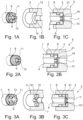
- Figure 1A shows a schematic isometric side view of a first end section of the first and male connecting element 1
- Figure 1B shows a schematic longitudinal sectional view of a second and female connecting element 3
- Figure 1C shows a schematic longitudinal section view of a connector connection 5 according to a first embodiment, which consists of the respective ones in the Figures 1A and 1B components shown is formed.
- the first connecting element 1 has a fluid channel 6 running along its axis and, at an end piece of the first connecting element 1, a radial sealing element/sealing ring 8, which is arranged in a circumferential groove 9 on the first connecting element 1.
- the recesses 13 are designed in such a way that they open/expire into the circumferential groove 9, in which the sealing element 8 is arranged, and at the same time break through the wall of the fluid channel 6 in the area of the end face 11. That in the Figures 1B and 1C
- the second connecting element 3 shown has a hollow cylindrical section for receiving the first connecting element 1, which is delimited by a stop surface 15. Furthermore, a funnel-shaped opening 16 is formed on the stop surface 15, which opens into a fluid channel 7 of the second connecting element 3. A (fluid) chamber 19 is formed between the end face 11 and the stop surface 15. Especially in the Fig.
- the multitude of recesses 13 on the first connecting element 1 can be seen, through which the circumferential groove 9 or one side of the sealing element 8 is fluidly connected to the fluid chamber 19 and thus to the fluid channel 7. Furthermore, the first connecting element 1 has a circumferential chamfer, which forms a transition between the end face 11 and the peripheral side of the first connecting element 1.
- Figure 2A shows the first connecting element 1 in a further advantageous embodiment
- Figure 2B shows a second embodiment of the connector connection 5 with the first connecting element 1 from the Figure 2A and the second connecting element 3 from the Figure 1B
- the recesses 13 are arranged on the first connecting element 1 in such a way that they do not penetrate the outer wall of the first connecting element 1, but rather rest against the inside of the first connecting element 1 and only penetrate the inner wall of the fluid channel 6 in the area of the front side 11.
- the recesses 13 extend axially through the first Connecting element 1 to the circumferential groove 9 in which the sealing element 8 is arranged.
- the circumferential groove 9 including the sealing element 8 is fluidically connected to the fluid channel 7 of the second connecting element 3.
- Figure 3A shows a schematic isometric side view of the first end portion of the first connecting element 1 in a further embodiment
- Figures 3B and 3C show a schematic longitudinal sectional view of the second connecting element 3 and the connector connection 5 according to a third advantageous embodiment.
- the first connecting element 1 of this embodiment differs from the embodiments described above in that the plurality of recesses 13 do not penetrate the wall of the fluid channel 6 or do not protrude into the fluid channel 6 of the first connecting element 1.
- the recesses 13 are arranged in the form of external openings. This enables fluid to flow from the end face 11 in the direction of the sealing element 8 or the circumferential groove 9.
- the second connecting element 3 of this third embodiment also has a plurality of further recesses 131 on its stop surface 15, which start from the fluid channel 7 and extend in the direction of the inner wall of the second connecting element 3.
- the connector connection 5 according to the third embodiment in Figure 3C shows that the recesses 11 on the first connecting element 1 and the recesses 131 on the inside of the second connecting element 3 are designed such that the sealing element 8 or the circumferential groove 9 on the first connecting element 1 and the fluid channel 7 are fluidically connected to one another. Fluid therefore flows via the recesses 11 and 131 to the sealing element 8 or away from it.
- FIGS. 4A and 4B show a schematic longitudinal section view of the first end section and the second connecting element 3 of a further embodiment.
- Figure 4C shows a schematic longitudinal section view of the connector connection 5 according to a fourth advantageous embodiment, which is from the in the Figures 4A and 4B components shown is composed.
- the radial sealing element 8 is on the inside of the second Connecting element 3, arranged in the form of a rod seal.
- the second connecting element 3 has recesses 131 and 132.
- the recesses 131 are as in the embodiment Figures 3B and 3C on the stop surface 15 and the recesses 132 on the inner lateral surface of the second connecting element 3, which surrounds the first connecting element 1 in the operating state.
- the recesses 131, 132 are designed in such a way that they adjoin one another and each overflow/run into one another. This creates the fluidic connection between the sealing element 8 and the fluid channel 7.
- FIGS. 5A and 5B show schematic longitudinal section views of the first end section of the first connecting element 1 and the second connecting element 3 of a further embodiment.
- Figure 5C shows a schematic longitudinal section view of the connector connection 5 according to a last, fifth embodiment, which is from the in the Figures 5A and 5B components shown is composed.
- the sealing element 8 is as in the embodiment Fig. 4B on the inside of the second connecting element 3, arranged in the form of a rod seal and the first connecting element 1 has recesses 13 according to FIG Fig. 1A shown embodiment.
- the formation of the recesses 13 on the first connecting element 1 enables a fluidic connection between the fluid channel 7 and the sealing element 8, since the recesses 13 of the first connecting element 1 adjoin the recesses 132 of the second connecting element 3.
- the fluid channel 7 of the cylinder housing 3 has a funnel-shaped opening 16.
Landscapes
- Engineering & Computer Science (AREA)
- General Engineering & Computer Science (AREA)
- Mechanical Engineering (AREA)
- Health & Medical Sciences (AREA)
- Heart & Thoracic Surgery (AREA)
- Hematology (AREA)
- Anesthesiology (AREA)
- Biomedical Technology (AREA)
- Pulmonology (AREA)
- Life Sciences & Earth Sciences (AREA)
- Animal Behavior & Ethology (AREA)
- General Health & Medical Sciences (AREA)
- Public Health (AREA)
- Veterinary Medicine (AREA)
- Infusion, Injection, And Reservoir Apparatuses (AREA)
- Quick-Acting Or Multi-Walled Pipe Joints (AREA)
Applications Claiming Priority (1)
| Application Number | Priority Date | Filing Date | Title |
|---|---|---|---|
| DE102022125309.0A DE102022125309A1 (de) | 2022-09-30 | 2022-09-30 | Totraumarme radiale Dichtung |
Publications (2)
| Publication Number | Publication Date |
|---|---|
| EP4345352A1 true EP4345352A1 (fr) | 2024-04-03 |
| EP4345352B1 EP4345352B1 (fr) | 2025-08-13 |
Family
ID=88147218
Family Applications (1)
| Application Number | Title | Priority Date | Filing Date |
|---|---|---|---|
| EP23198704.1A Active EP4345352B1 (fr) | 2022-09-30 | 2023-09-21 | Connecteur médical avec joint radial à faible espace mort |
Country Status (4)
| Country | Link |
|---|---|
| US (1) | US12404955B2 (fr) |
| EP (1) | EP4345352B1 (fr) |
| CN (1) | CN221451494U (fr) |
| DE (1) | DE102022125309A1 (fr) |
Citations (5)
| Publication number | Priority date | Publication date | Assignee | Title |
|---|---|---|---|---|
| GB2000240A (en) * | 1977-06-10 | 1979-01-04 | Thyssen Industrie | Pipeline joints |
| DE2855646A1 (de) * | 1978-12-22 | 1980-06-26 | Thyssen Industrie | Einschub-muffenverbindung fuer insbesondere duktile gussrohre |
| EP0406144A1 (fr) * | 1989-06-28 | 1991-01-02 | Pont-A-Mousson S.A. | Garniture d'étanchéité à talon annulaire d'ancrage |
| EP1574774B1 (fr) | 2004-02-25 | 2007-06-27 | Atec Pharmatechnik Gmbh | Dispositif d'étanchéité |
| CN202834069U (zh) | 2012-09-24 | 2013-03-27 | 哈尔滨三联药业有限公司 | 一种可在线清洁、灭菌的洁净级别釜用机械密封装置 |
Family Cites Families (6)
| Publication number | Priority date | Publication date | Assignee | Title |
|---|---|---|---|---|
| US4398726A (en) * | 1981-07-06 | 1983-08-16 | J-M Manufacturing Company Inc. | Pipe section including a gasketed spigot end and method of making the same |
| US4905766A (en) * | 1987-04-28 | 1990-03-06 | R&G Sloane Mfg. Co., Inc. | Adapter for plastic pipe |
| US5395139A (en) * | 1993-06-29 | 1995-03-07 | Pro-Mark, Inc. | Swivel type adapter pipe fitting for sprinkler or drip-type irrigation systems |
| DE19628551B4 (de) * | 1995-08-04 | 2004-04-15 | Ifm Electronic Gmbh | Druckmeßgerät und Druckmeßanordnung |
| DE10023692A1 (de) * | 2000-05-16 | 2001-11-22 | Neumo Gmbh & Co Kg | Verbindung für medienführende Teile |
| US9814870B2 (en) | 2010-08-17 | 2017-11-14 | Becton, Dickinson And Company | Non-luer connectors |
-
2022
- 2022-09-30 DE DE102022125309.0A patent/DE102022125309A1/de active Pending
-
2023
- 2023-09-21 EP EP23198704.1A patent/EP4345352B1/fr active Active
- 2023-09-27 US US18/475,689 patent/US12404955B2/en active Active
- 2023-09-28 CN CN202322657022.2U patent/CN221451494U/zh active Active
Patent Citations (5)
| Publication number | Priority date | Publication date | Assignee | Title |
|---|---|---|---|---|
| GB2000240A (en) * | 1977-06-10 | 1979-01-04 | Thyssen Industrie | Pipeline joints |
| DE2855646A1 (de) * | 1978-12-22 | 1980-06-26 | Thyssen Industrie | Einschub-muffenverbindung fuer insbesondere duktile gussrohre |
| EP0406144A1 (fr) * | 1989-06-28 | 1991-01-02 | Pont-A-Mousson S.A. | Garniture d'étanchéité à talon annulaire d'ancrage |
| EP1574774B1 (fr) | 2004-02-25 | 2007-06-27 | Atec Pharmatechnik Gmbh | Dispositif d'étanchéité |
| CN202834069U (zh) | 2012-09-24 | 2013-03-27 | 哈尔滨三联药业有限公司 | 一种可在线清洁、灭菌的洁净级别釜用机械密封装置 |
Also Published As
| Publication number | Publication date |
|---|---|
| CN221451494U (zh) | 2024-08-02 |
| US12404955B2 (en) | 2025-09-02 |
| DE102022125309A1 (de) | 2024-04-04 |
| US20240110649A1 (en) | 2024-04-04 |
| EP4345352B1 (fr) | 2025-08-13 |
Similar Documents
| Publication | Publication Date | Title |
|---|---|---|
| DE69706178T2 (de) | Schnellverbindungs- und trennkupplung für elektropumpen und leitungen für eine scheibenreinigungsanlage eines kraftfahrzeugs | |
| DE102012108566B4 (de) | Steckereinheit und Verbindungseinrichtung für Flüssigkeit führende Komponenten, insbesondere für die Hochleistungsflüssigkeitschromatographie | |
| DE2901306A1 (de) | Schnelltrennduese | |
| DE3519773A1 (de) | Steckverbindung fuer bohrgestaenge von erdbohrgeraeten | |
| DE20205833U1 (de) | Steckkupplung für fluidische Systeme | |
| EP3608045A1 (fr) | Mandrin de serrage à expansion hydraulique | |
| DE60017999T2 (de) | Verbindungsmittel für Anschliessen eines Rohres an röhrenförmigen Körper | |
| EP0781386A1 (fr) | Raccord pour la piece d'accouplement des tuyaux d'un appareil de nettoyage a haute pression | |
| DE4002558C2 (de) | Hydraulikzylinder | |
| EP4345352B1 (fr) | Connecteur médical avec joint radial à faible espace mort | |
| EP4390207B1 (fr) | Pièce d'accouplement pour un accouplement hydraulique | |
| EP3803180B1 (fr) | Dispositif de raccordement pour un ensemble de tuyaux souples | |
| DE69820360T2 (de) | Hydraulikpumpenanlage | |
| EP2801725B1 (fr) | Dispositif comprenant au moins un canal pour l'acheminement d'un fluide de travail gazeux ou liquide | |
| DE102004029641B4 (de) | Vorrichtung zum Filtern von Fluiden | |
| DE3616964C2 (de) | Anschlußverbindungsstück | |
| DE69413719T2 (de) | Vorrichtung für doppeltwirkende hydraulische systeme | |
| EP1770320A1 (fr) | Raccord détachable à fiche pour des tuyaux | |
| EP2402638B1 (fr) | Agencement de liaison destiné à la liaison de deux composants | |
| DE102009000752B4 (de) | Kraftstoffeinspritzvorrichtung | |
| EP2023027A2 (fr) | Jonction tubulaire | |
| WO2020260128A1 (fr) | Bloc de commande hydraulique et axe servo-hydraulique pourvu dudit bloc de commande | |
| DE29806381U1 (de) | Anschlußelement | |
| DE102005005452A1 (de) | Systemtrenner | |
| DE102014009831A1 (de) | Mehrteiliger, konzentrischer Verteiler und Verfahren zur Herstellung des Verteilers |
Legal Events
| Date | Code | Title | Description |
|---|---|---|---|
| PUAI | Public reference made under article 153(3) epc to a published international application that has entered the european phase |
Free format text: ORIGINAL CODE: 0009012 |
|
| STAA | Information on the status of an ep patent application or granted ep patent |
Free format text: STATUS: THE APPLICATION HAS BEEN PUBLISHED |
|
| AK | Designated contracting states |
Kind code of ref document: A1 Designated state(s): AL AT BE BG CH CY CZ DE DK EE ES FI FR GB GR HR HU IE IS IT LI LT LU LV MC ME MK MT NL NO PL PT RO RS SE SI SK SM TR |
|
| STAA | Information on the status of an ep patent application or granted ep patent |
Free format text: STATUS: REQUEST FOR EXAMINATION WAS MADE |
|
| 17P | Request for examination filed |
Effective date: 20240801 |
|
| RBV | Designated contracting states (corrected) |
Designated state(s): AL AT BE BG CH CY CZ DE DK EE ES FI FR GB GR HR HU IE IS IT LI LT LU LV MC ME MK MT NL NO PL PT RO RS SE SI SK SM TR |
|
| GRAP | Despatch of communication of intention to grant a patent |
Free format text: ORIGINAL CODE: EPIDOSNIGR1 |
|
| STAA | Information on the status of an ep patent application or granted ep patent |
Free format text: STATUS: GRANT OF PATENT IS INTENDED |
|
| RIC1 | Information provided on ipc code assigned before grant |
Ipc: A61M 39/16 20060101ALI20250225BHEP Ipc: A61M 39/14 20060101ALI20250225BHEP Ipc: A61M 39/10 20060101ALI20250225BHEP Ipc: F16L 21/035 20060101ALI20250225BHEP Ipc: F16L 21/03 20060101AFI20250225BHEP |
|
| INTG | Intention to grant announced |
Effective date: 20250319 |
|
| GRAS | Grant fee paid |
Free format text: ORIGINAL CODE: EPIDOSNIGR3 |
|
| GRAA | (expected) grant |
Free format text: ORIGINAL CODE: 0009210 |
|
| STAA | Information on the status of an ep patent application or granted ep patent |
Free format text: STATUS: THE PATENT HAS BEEN GRANTED |
|
| AK | Designated contracting states |
Kind code of ref document: B1 Designated state(s): AL AT BE BG CH CY CZ DE DK EE ES FI FR GB GR HR HU IE IS IT LI LT LU LV MC ME MK MT NL NO PL PT RO RS SE SI SK SM TR |
|
| REG | Reference to a national code |
Ref country code: GB Ref legal event code: FG4D Free format text: NOT ENGLISH |
|
| REG | Reference to a national code |
Ref country code: CH Ref legal event code: EP |
|
| REG | Reference to a national code |
Ref country code: DE Ref legal event code: R096 Ref document number: 502023001573 Country of ref document: DE |
|
| REG | Reference to a national code |
Ref country code: IE Ref legal event code: FG4D Free format text: LANGUAGE OF EP DOCUMENT: GERMAN |
|
| PGFP | Annual fee paid to national office [announced via postgrant information from national office to epo] |
Ref country code: AT Payment date: 20251020 Year of fee payment: 3 |
|
| REG | Reference to a national code |
Ref country code: NL Ref legal event code: MP Effective date: 20250813 |
|
| PG25 | Lapsed in a contracting state [announced via postgrant information from national office to epo] |
Ref country code: IS Free format text: LAPSE BECAUSE OF FAILURE TO SUBMIT A TRANSLATION OF THE DESCRIPTION OR TO PAY THE FEE WITHIN THE PRESCRIBED TIME-LIMIT Effective date: 20251213 |
|
| PGFP | Annual fee paid to national office [announced via postgrant information from national office to epo] |
Ref country code: DE Payment date: 20250929 Year of fee payment: 3 |
|
| PG25 | Lapsed in a contracting state [announced via postgrant information from national office to epo] |
Ref country code: NO Free format text: LAPSE BECAUSE OF FAILURE TO SUBMIT A TRANSLATION OF THE DESCRIPTION OR TO PAY THE FEE WITHIN THE PRESCRIBED TIME-LIMIT Effective date: 20251113 |
|
| REG | Reference to a national code |
Ref country code: LT Ref legal event code: MG9D |
|
| PG25 | Lapsed in a contracting state [announced via postgrant information from national office to epo] |
Ref country code: PT Free format text: LAPSE BECAUSE OF FAILURE TO SUBMIT A TRANSLATION OF THE DESCRIPTION OR TO PAY THE FEE WITHIN THE PRESCRIBED TIME-LIMIT Effective date: 20251215 |
|
| PG25 | Lapsed in a contracting state [announced via postgrant information from national office to epo] |
Ref country code: FI Free format text: LAPSE BECAUSE OF FAILURE TO SUBMIT A TRANSLATION OF THE DESCRIPTION OR TO PAY THE FEE WITHIN THE PRESCRIBED TIME-LIMIT Effective date: 20250813 |
|
| PGFP | Annual fee paid to national office [announced via postgrant information from national office to epo] |
Ref country code: IT Payment date: 20250930 Year of fee payment: 3 |
|
| PG25 | Lapsed in a contracting state [announced via postgrant information from national office to epo] |
Ref country code: HR Free format text: LAPSE BECAUSE OF FAILURE TO SUBMIT A TRANSLATION OF THE DESCRIPTION OR TO PAY THE FEE WITHIN THE PRESCRIBED TIME-LIMIT Effective date: 20250813 Ref country code: NL Free format text: LAPSE BECAUSE OF FAILURE TO SUBMIT A TRANSLATION OF THE DESCRIPTION OR TO PAY THE FEE WITHIN THE PRESCRIBED TIME-LIMIT Effective date: 20250813 |
|
| PG25 | Lapsed in a contracting state [announced via postgrant information from national office to epo] |
Ref country code: GR Free format text: LAPSE BECAUSE OF FAILURE TO SUBMIT A TRANSLATION OF THE DESCRIPTION OR TO PAY THE FEE WITHIN THE PRESCRIBED TIME-LIMIT Effective date: 20251114 |
|
| PG25 | Lapsed in a contracting state [announced via postgrant information from national office to epo] |
Ref country code: SE Free format text: LAPSE BECAUSE OF FAILURE TO SUBMIT A TRANSLATION OF THE DESCRIPTION OR TO PAY THE FEE WITHIN THE PRESCRIBED TIME-LIMIT Effective date: 20250813 |
|
| PG25 | Lapsed in a contracting state [announced via postgrant information from national office to epo] |
Ref country code: LV Free format text: LAPSE BECAUSE OF FAILURE TO SUBMIT A TRANSLATION OF THE DESCRIPTION OR TO PAY THE FEE WITHIN THE PRESCRIBED TIME-LIMIT Effective date: 20250813 |
|
| PG25 | Lapsed in a contracting state [announced via postgrant information from national office to epo] |
Ref country code: BG Free format text: LAPSE BECAUSE OF FAILURE TO SUBMIT A TRANSLATION OF THE DESCRIPTION OR TO PAY THE FEE WITHIN THE PRESCRIBED TIME-LIMIT Effective date: 20250813 Ref country code: PL Free format text: LAPSE BECAUSE OF FAILURE TO SUBMIT A TRANSLATION OF THE DESCRIPTION OR TO PAY THE FEE WITHIN THE PRESCRIBED TIME-LIMIT Effective date: 20250813 |
|
| PG25 | Lapsed in a contracting state [announced via postgrant information from national office to epo] |
Ref country code: RS Free format text: LAPSE BECAUSE OF FAILURE TO SUBMIT A TRANSLATION OF THE DESCRIPTION OR TO PAY THE FEE WITHIN THE PRESCRIBED TIME-LIMIT Effective date: 20251113 |
|
| PG25 | Lapsed in a contracting state [announced via postgrant information from national office to epo] |
Ref country code: ES Free format text: LAPSE BECAUSE OF FAILURE TO SUBMIT A TRANSLATION OF THE DESCRIPTION OR TO PAY THE FEE WITHIN THE PRESCRIBED TIME-LIMIT Effective date: 20250813 |
|
| PG25 | Lapsed in a contracting state [announced via postgrant information from national office to epo] |
Ref country code: RO Free format text: LAPSE BECAUSE OF FAILURE TO SUBMIT A TRANSLATION OF THE DESCRIPTION OR TO PAY THE FEE WITHIN THE PRESCRIBED TIME-LIMIT Effective date: 20250813 |
|
| PG25 | Lapsed in a contracting state [announced via postgrant information from national office to epo] |
Ref country code: SM Free format text: LAPSE BECAUSE OF FAILURE TO SUBMIT A TRANSLATION OF THE DESCRIPTION OR TO PAY THE FEE WITHIN THE PRESCRIBED TIME-LIMIT Effective date: 20250813 |
|
| PG25 | Lapsed in a contracting state [announced via postgrant information from national office to epo] |
Ref country code: DK Free format text: LAPSE BECAUSE OF FAILURE TO SUBMIT A TRANSLATION OF THE DESCRIPTION OR TO PAY THE FEE WITHIN THE PRESCRIBED TIME-LIMIT Effective date: 20250813 |
|
| PG25 | Lapsed in a contracting state [announced via postgrant information from national office to epo] |
Ref country code: CZ Free format text: LAPSE BECAUSE OF FAILURE TO SUBMIT A TRANSLATION OF THE DESCRIPTION OR TO PAY THE FEE WITHIN THE PRESCRIBED TIME-LIMIT Effective date: 20250813 |
|
| PG25 | Lapsed in a contracting state [announced via postgrant information from national office to epo] |
Ref country code: EE Free format text: LAPSE BECAUSE OF FAILURE TO SUBMIT A TRANSLATION OF THE DESCRIPTION OR TO PAY THE FEE WITHIN THE PRESCRIBED TIME-LIMIT Effective date: 20250813 Ref country code: SK Free format text: LAPSE BECAUSE OF FAILURE TO SUBMIT A TRANSLATION OF THE DESCRIPTION OR TO PAY THE FEE WITHIN THE PRESCRIBED TIME-LIMIT Effective date: 20250813 |