EP4345357A1 - Verschlussvorrichtung zum dichten verschliessen eines loches - Google Patents
Verschlussvorrichtung zum dichten verschliessen eines loches Download PDFInfo
- Publication number
- EP4345357A1 EP4345357A1 EP22198361.2A EP22198361A EP4345357A1 EP 4345357 A1 EP4345357 A1 EP 4345357A1 EP 22198361 A EP22198361 A EP 22198361A EP 4345357 A1 EP4345357 A1 EP 4345357A1
- Authority
- EP
- European Patent Office
- Prior art keywords
- base body
- sleeve
- closure device
- shaped base
- head
- Prior art date
- Legal status (The legal status is an assumption and is not a legal conclusion. Google has not performed a legal analysis and makes no representation as to the accuracy of the status listed.)
- Granted
Links
Images


Classifications
-
- F—MECHANICAL ENGINEERING; LIGHTING; HEATING; WEAPONS; BLASTING
- F16—ENGINEERING ELEMENTS AND UNITS; GENERAL MEASURES FOR PRODUCING AND MAINTAINING EFFECTIVE FUNCTIONING OF MACHINES OR INSTALLATIONS; THERMAL INSULATION IN GENERAL
- F16L—PIPES; JOINTS OR FITTINGS FOR PIPES; SUPPORTS FOR PIPES, CABLES OR PROTECTIVE TUBING; MEANS FOR THERMAL INSULATION IN GENERAL
- F16L55/00—Devices or appurtenances for use in, or in connection with, pipes or pipe systems
- F16L55/10—Means for stopping flow in pipes or hoses
- F16L55/12—Means for stopping flow in pipes or hoses by introducing into the pipe a member expandable in situ
- F16L55/128—Means for stopping flow in pipes or hoses by introducing into the pipe a member expandable in situ introduced axially into the pipe or hose
- F16L55/13—Means for stopping flow in pipes or hoses by introducing into the pipe a member expandable in situ introduced axially into the pipe or hose the closure device being a plug fixed by plastic deformation
-
- F—MECHANICAL ENGINEERING; LIGHTING; HEATING; WEAPONS; BLASTING
- F16—ENGINEERING ELEMENTS AND UNITS; GENERAL MEASURES FOR PRODUCING AND MAINTAINING EFFECTIVE FUNCTIONING OF MACHINES OR INSTALLATIONS; THERMAL INSULATION IN GENERAL
- F16B—DEVICES FOR FASTENING OR SECURING CONSTRUCTIONAL ELEMENTS OR MACHINE PARTS TOGETHER, e.g. NAILS, BOLTS, CIRCLIPS, CLAMPS, CLIPS OR WEDGES; JOINTS OR JOINTING
- F16B13/00—Dowels or other devices fastened in walls or the like by inserting them in holes made therein for that purpose
- F16B13/04—Dowels or other devices fastened in walls or the like by inserting them in holes made therein for that purpose with parts gripping in the hole or behind the reverse side of the wall after inserting from the front
- F16B13/06—Dowels or other devices fastened in walls or the like by inserting them in holes made therein for that purpose with parts gripping in the hole or behind the reverse side of the wall after inserting from the front combined with expanding sleeve
- F16B13/063—Dowels or other devices fastened in walls or the like by inserting them in holes made therein for that purpose with parts gripping in the hole or behind the reverse side of the wall after inserting from the front combined with expanding sleeve by the use of an expander
-
- F—MECHANICAL ENGINEERING; LIGHTING; HEATING; WEAPONS; BLASTING
- F16—ENGINEERING ELEMENTS AND UNITS; GENERAL MEASURES FOR PRODUCING AND MAINTAINING EFFECTIVE FUNCTIONING OF MACHINES OR INSTALLATIONS; THERMAL INSULATION IN GENERAL
- F16B—DEVICES FOR FASTENING OR SECURING CONSTRUCTIONAL ELEMENTS OR MACHINE PARTS TOGETHER, e.g. NAILS, BOLTS, CIRCLIPS, CLAMPS, CLIPS OR WEDGES; JOINTS OR JOINTING
- F16B19/00—Bolts without screw-thread; Pins, including deformable elements; Rivets
- F16B19/02—Bolts or sleeves for positioning of machine parts, e.g. notched taper pins, fitting pins, sleeves, eccentric positioning rings
-
- F—MECHANICAL ENGINEERING; LIGHTING; HEATING; WEAPONS; BLASTING
- F16—ENGINEERING ELEMENTS AND UNITS; GENERAL MEASURES FOR PRODUCING AND MAINTAINING EFFECTIVE FUNCTIONING OF MACHINES OR INSTALLATIONS; THERMAL INSULATION IN GENERAL
- F16B—DEVICES FOR FASTENING OR SECURING CONSTRUCTIONAL ELEMENTS OR MACHINE PARTS TOGETHER, e.g. NAILS, BOLTS, CIRCLIPS, CLAMPS, CLIPS OR WEDGES; JOINTS OR JOINTING
- F16B19/00—Bolts without screw-thread; Pins, including deformable elements; Rivets
- F16B19/04—Rivets; Spigots or the like fastened by riveting
- F16B19/08—Hollow rivets; Multi-part rivets
- F16B19/10—Hollow rivets; Multi-part rivets fastened by expanding mechanically
- F16B19/1027—Multi-part rivets
- F16B19/1036—Blind rivets
- F16B19/1045—Blind rivets fastened by a pull - mandrel or the like
- F16B19/1054—Blind rivets fastened by a pull - mandrel or the like the pull-mandrel or the like being frangible
-
- F—MECHANICAL ENGINEERING; LIGHTING; HEATING; WEAPONS; BLASTING
- F16—ENGINEERING ELEMENTS AND UNITS; GENERAL MEASURES FOR PRODUCING AND MAINTAINING EFFECTIVE FUNCTIONING OF MACHINES OR INSTALLATIONS; THERMAL INSULATION IN GENERAL
- F16B—DEVICES FOR FASTENING OR SECURING CONSTRUCTIONAL ELEMENTS OR MACHINE PARTS TOGETHER, e.g. NAILS, BOLTS, CIRCLIPS, CLAMPS, CLIPS OR WEDGES; JOINTS OR JOINTING
- F16B43/00—Washers or equivalent devices; Other devices for supporting bolt-heads or nuts
- F16B43/001—Washers or equivalent devices; Other devices for supporting bolt-heads or nuts for sealing or insulation
-
- F—MECHANICAL ENGINEERING; LIGHTING; HEATING; WEAPONS; BLASTING
- F16—ENGINEERING ELEMENTS AND UNITS; GENERAL MEASURES FOR PRODUCING AND MAINTAINING EFFECTIVE FUNCTIONING OF MACHINES OR INSTALLATIONS; THERMAL INSULATION IN GENERAL
- F16B—DEVICES FOR FASTENING OR SECURING CONSTRUCTIONAL ELEMENTS OR MACHINE PARTS TOGETHER, e.g. NAILS, BOLTS, CIRCLIPS, CLAMPS, CLIPS OR WEDGES; JOINTS OR JOINTING
- F16B43/00—Washers or equivalent devices; Other devices for supporting bolt-heads or nuts
- F16B43/02—Washers or equivalent devices; Other devices for supporting bolt-heads or nuts with special provisions for engaging surfaces which are not perpendicular to a bolt axis or do not surround the bolt
Definitions
- the present invention relates to a closure device for tight sealing a hole, comprising a sleeve shaped base body and an expander element with the features of the preamble of claim 1.
- closure devices are primarily used in automotive, pneumatic, hydraulic and aerospace applications, such as for example as for the seals of bores in vehicle engines or of bores in hydraulic or pneumatic valves etc.. These closure devices can be described as pull expanders used in bores of apparatus bodies.
- WO 2012/107059 A1 discloses a closure element for internally pressurized bores in components comprising a closure disc that can be inserted into the bore largely without any play and that can be spread apart by an axially applied tension and can thereby be pressed radially against the inner wall of the bore to be closed.
- Said closure disc is the head part of a tensioning pin which can be tensioned and that this tensioning pin has a predetermined breaking point at which it can be separated from the closure disc upon reaching a specific tensile stress.
- US 5,078,294 A discloses a method for tight sealing of a hole comprising forcing an essentially bushing- or tube-shaped plug into the hole and radially expanding the plug wall along at least one axial segment to produce a tight seal of the plug against the hole, wherein the plug is anchored positively and axially in the hole in order to prevent axial piston-like movement of the plug in the hole.
- the tightly sealed hole arrangement of the invention comprises as essentially bushing-shaped or tubular plug with a radially spread axial part fitting tightly in the hole for sealing the hole, and wherein a positively axially acting locking arrangement is provided between the hole and the plug, in order to provide a piston-like displacement of the plug in the hole, and wherein the sealing and the locking parts are provided axially at different points.
- the method is accomplished using an expansion element by pulling this element into the plug.
- An opening is provided in the base of the bushing-shaped plug, through which a pulling armature which can be broken off later and with an expansion element at the end is guided, and the latter is pulled into the plug.
- Expansion element comprises a frustoconical end expansion part, followed by a sealing part with slightly smaller diameter for through hole, and next to that, with a breaking point, a pulling element. Pulling element is guided through opening and expansion element is pulled into bushing at plug by pulling, whereby its wall, possibly roughened, is pressed radially against the hole wall which may also be roughened to form sealing part. Locking part is formed by the intermeshing of the two threads. After expansion element has been driven in, pulling element is broken off at breaking point.
- the invention is based on a closure device with the features of claim 1.
- Both the sleeve-shaped base body and the expander element with the splaying body as well as the tensioning pin or pulling element and the predetermined breaking point in a breaking groove are made out of aluminum alloys and produced by cold forming process and subsequent hardening process. This makes the closure element and pull expander fully resistant against corrosion, therefore extending its range of applications and in general its fatigue life lifetime.
- the material compatibility of the two components of the expander, and therefore the compatibility of their physical properties, especially the thermal expansion coefficient, improves the durability of the expander by reducing the incidence of internal cracks over several temperature cycles, both at the surface and in the bulk of the material.
- the cold forming and hardening processes used to manufacture the parts also improve the overall quality of the expander by further reducing the occurrence and probability of cracks formation both at the surface and in the bulk of the material.
- Most of the parts that require sealing in electric vehicles are made out of aluminum, to reduce the weight and because it's non-magnetic. Therefore, a full-aluminum sealing plug brings a clear advantage for applications in E-mobility, because it ensures the compatibility of the physical properties between the sealing plug and the hosting body.
- the improved material quality especially the reduction of cracks formation in the bulk given by the cold forming manufacturing process makes it possible to increase the assembling force of the expander compared to standard aluminum parts manufactured by turning process.
- the peculiar characteristic of the described closure element is that both the sleeve-shaped base body and the splaying body, as well as the tensioning pin/pulling element and the predetermined breaking point area are made out of aluminum alloys.
- the breaking point area is a part of the base body having a groove, i.e. the body is of lesser diameter.
- Aluminum alloys can have different compositions, preferred aluminum alloys are AI-6056 for the mandrel and AI-6060 for the sleeve.
- the base body and splaying body are produced by a cold forming process and subsequent hardening process, especially a T6 hardening process is done after cold forming of the part. This characteristics makes the expander fully resistant against corrosion, therefore extending its range of applications and in general its fatigue life.
- the closure element is made out of aluminum for inserting into a bore in a component, such as into a bore in an engine, a valve block manifold, a hydraulic unit or a container.
- the said closure element consists of a sleeve-shaped base body that can be inserted into a bore, the outer circumference of which in the fitted state lies tight against the inner surface of the bore.
- a splaying body that can brace this base body in the bore is characterized in that the base body and the splaying body, connected to the tension bolt via a predetermined breaking point, can be positioned in the bore, and that by applying a force to the tension bolt, the splaying body can be pushed into the base body.
- the predetermined breaking area shears off the splaying body, so that the splaying body presses the base body tight against the wall of the bore to be closed by producing a radial pressure on the inner wall of the base body.
- the easy-to-handle tensioning pin facilitates the installation of the closure element in the bore. Since the base body is pressed against an outer counter holder during the installation process, it can be inserted into a continuously smooth bore.
- the limitation of the tensile stress effected by design by the predetermined breaking area also ensures that the bore is closed with a defined closing force, which makes the process highly accurate and reproducible.
- Fig. 1 shows a schematic view of a first embodiment of the closure device in the mounted position in a bore in an apparatus body.
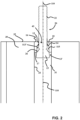
- Fig. 2 shows the closure device 100 of Fig. 1 in a position where the base body 10 is positioned in the smooth bore 31 but the expander element 20 is not yet pulled back, i.e. the frustoconical head 24 is still in the bore 31 outside of the head receiving portion 115.
- Fig. 3 shows the elements of Fig. 1 after rupture of the pulling element 22 at the breaking groove 23.
- Such a closure device 100 comprises a sleeve-shaped base body 10 and an expander element 20, wherein the expander element 20 comprises a splaying body 21 and a pulling element 22 with a breaking groove 23 between them. Beside a breaking groove 23, it can be a structurally weaker section.
- the splaying body 21 has a frustoconical head 15 with the smaller diameter of the head oriented towards the breaking groove 23.
- the sleeve-shaped base body 10 has in the longitudinal direction 110 a head receiving portion 115 followed by a tapering shoulder portion 14 and a central opening 12 having an inner cylindrical surface 13 configured to allow to pass the outer diameter of the pulling element 22.
- This closure device 100 is shown as being mounted in a smooth bore 21 of an apparatus body 30.
- the outer diameter of the base body 10 is configured to be introduced into the smooth bore 21 of the apparatus body 30 without almost no play.
- the base body 10 is of hollow cylindrical design with an outer cylindrical surface 11 having preferably two parallel surfaces 16 and 17.
- the outside directed surface 16 is provided directed to the mouth of the smooth bore 31 whereas the inside directed surface 17 is oriented towards the depth of said bore 31.
- the hollow cylindrical base body 10 has at least three different portions between the two surfaces 16 and 17. Starting from the inside with surface 17, it comprises a head receiving portion 115 followed by a tapering shoulder portion 14 and an inner cylindrical surface portion 13.
- the head receiving portion 115 can have a cylindrical surface 113' like in the embodiment of Fig. 4 or a conical surface 113 like in the embodiments of Fig. 5 or Fig. 6 .
- Fig. 3 shows a detail view of an embodiment of the base body 10.
- the embodiment of Fig. 3 has a circumferential groove 18 in the outside directed surface 16 creating an inner guiding wall 19.
- the circumferential groove 18 can have - in radial direction - an outer cylindrical groove surface 13'.
- the surface 13' In its longitudinal direction 110 the surface 13' can be in the essentially same radial distance as the cylindrical surface 113' of the head receiving portion and being parallel to the surface 13, creating a similar diameter comprising wall of the base body 10 (between the outer surface 11 and the inner surface 113' or 13').
- the feature of a cut in the lower part of the sleeve facilitates the insertion of the mandrel head 24 either by progressively enhancing the bending of the sleeve 10 on itself or by reducing the resistance force during the installation of the expander 20. Therefore, it reduces the risk of breaking the mandrel/pulling expander 22 before the head 24 is completely inside the sleeve 10.
- the groove 18 can also be inside the sleeve as groove 18'.
- Fig. 5' shows a detail view of the sleeve-shaped base body according to such a further modified embodiment.
- “Inside” refers to the groove 18' manufactured as a circular groove adjacent to the inner walls of the sleeve, with its main symmetry axis 110 coincident with the main symmetry axis of the expander. Therefore, in this situation, the groove is not visible when the mandrel-sleeve system is in its pre-assembled state.
- the head 15 presses on the shoulder portion 14 and the circumferential groove 18' allows the expansion of this part of the sleeve, while the wall of the sleeve with its cylindrical surface 113' extends from the inside directed surface until the depth of the inner cylindrical groove 18'.
- the edge surface can be chamfered surfaces 117 and 118.
- External chamfered surface 117 of e.g. 45 degree inclination allows an easier introduction of the base body 10 in the smooth bore 31 with its cylindrical bore surface 33.
- the inner chamfered surface 118 allows an easier introduction and longitudinal movement along longitudinal direction 110 of the head portion 15.
- Fig. 5 shows a further detail view of a modified expander element 20 with an hollow head cavity 28.
- Cylindrical inner head receiving portions 115 can comprise a hollow head cavity 28 as shown in Fig. 6 as well.
- This hollow head cavity 28 can be provided in with grooves 18 or 18'.
- the angle can be between 1° and 10°, especially between 3° and 7° and especially 5°.
- the cavity 28 in the mandrel head 24 reduces the shear force on the sleeve and increases the radial component of the force after installation by allowing some elastic deformation of the mandrel head in the radial direction.
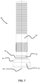
- Fig. 6 shows a cross-section view of the base body 10 and Fig. 7 shows a side view of the expander element 20.
- the present invention allows for a larger ratio between the diameters of the tensioning pin 2 and the breaking groove 23, as well as a larger ratio between the diameters of the head 15 and the inner diameter of the base body 10.
- the first allows to have higher installation force and a better defined breaking section, while the latter allows to reduce the shear resistance in the installation phase and improve the radial transmission of plastic deformation.
- a larger shaft diameter is chosen for higher setting force; an increased head diameter to sleeve wall thickness ratio is chosen for optimized installation,
- the ratio of the diameter of the breaking section d groove compared to the diameter d shaft of the pulling shaft 22 can be chosen larger, i.e. d shaft /d groove ratio is larger than for known steel mandrel. Such a larger ratio statistically improves the reliability of the installation process over very large numbers of repetitions.
- Both functions of sealing and anchoring of the outer surface of the sleeve 10 to the inner surface of the bore are achieved by material hardening and treatment by cold forming process, roughness optimization and subsequent further surface hardening which increases the hardness of the micro-asperities on the surface.
- the sleeve and the expander are produced by cold forming, which increases the material hardness and improves the surface roughness properties. Then, a subsequent T6 hardening process, to increase the material robustness even further.
Landscapes
- Engineering & Computer Science (AREA)
- General Engineering & Computer Science (AREA)
- Mechanical Engineering (AREA)
- Pressure Vessels And Lids Thereof (AREA)
Priority Applications (1)
| Application Number | Priority Date | Filing Date | Title |
|---|---|---|---|
| EP22198361.2A EP4345357B1 (de) | 2022-09-28 | 2022-09-28 | Verschlussvorrichtung zum dichten verschliessen eines loches |
Applications Claiming Priority (1)
| Application Number | Priority Date | Filing Date | Title |
|---|---|---|---|
| EP22198361.2A EP4345357B1 (de) | 2022-09-28 | 2022-09-28 | Verschlussvorrichtung zum dichten verschliessen eines loches |
Publications (3)
| Publication Number | Publication Date |
|---|---|
| EP4345357A1 true EP4345357A1 (de) | 2024-04-03 |
| EP4345357C0 EP4345357C0 (de) | 2025-11-05 |
| EP4345357B1 EP4345357B1 (de) | 2025-11-05 |
Family
ID=83505812
Family Applications (1)
| Application Number | Title | Priority Date | Filing Date |
|---|---|---|---|
| EP22198361.2A Active EP4345357B1 (de) | 2022-09-28 | 2022-09-28 | Verschlussvorrichtung zum dichten verschliessen eines loches |
Country Status (1)
| Country | Link |
|---|---|
| EP (1) | EP4345357B1 (de) |
Cited By (1)
| Publication number | Priority date | Publication date | Assignee | Title |
|---|---|---|---|---|
| WO2025219532A1 (en) * | 2024-04-18 | 2025-10-23 | Avdel Uk Ltd. | Two-piece sealing plugs for blind hole, one-sided installation |
Citations (6)
| Publication number | Priority date | Publication date | Assignee | Title |
|---|---|---|---|---|
| US3525365A (en) * | 1966-10-17 | 1970-08-25 | Pneumo Dynamics Corp | Expansion plug |
| US5078294A (en) | 1988-09-16 | 1992-01-07 | Koenig Berbindungstechnik Ag | Method for tight sealing and hole arrangement |
| EP0877193A1 (de) * | 1997-05-09 | 1998-11-11 | Creda Limited | Gas-Zuleitung |
| US20030178793A1 (en) * | 2000-05-11 | 2003-09-25 | Keith Denham | Closed end sealing plug |
| WO2012107059A1 (de) | 2011-02-12 | 2012-08-16 | Kvt-Koenig Ag | Verschlusselement für innendruckbeaufschlagte bohrungen von bauteilen |
| EP3312105A1 (de) * | 2016-10-21 | 2018-04-25 | HS Wroclaw Sp. z o.o. | Hydraulikstecker |
-
2022
- 2022-09-28 EP EP22198361.2A patent/EP4345357B1/de active Active
Patent Citations (6)
| Publication number | Priority date | Publication date | Assignee | Title |
|---|---|---|---|---|
| US3525365A (en) * | 1966-10-17 | 1970-08-25 | Pneumo Dynamics Corp | Expansion plug |
| US5078294A (en) | 1988-09-16 | 1992-01-07 | Koenig Berbindungstechnik Ag | Method for tight sealing and hole arrangement |
| EP0877193A1 (de) * | 1997-05-09 | 1998-11-11 | Creda Limited | Gas-Zuleitung |
| US20030178793A1 (en) * | 2000-05-11 | 2003-09-25 | Keith Denham | Closed end sealing plug |
| WO2012107059A1 (de) | 2011-02-12 | 2012-08-16 | Kvt-Koenig Ag | Verschlusselement für innendruckbeaufschlagte bohrungen von bauteilen |
| EP3312105A1 (de) * | 2016-10-21 | 2018-04-25 | HS Wroclaw Sp. z o.o. | Hydraulikstecker |
Cited By (1)
| Publication number | Priority date | Publication date | Assignee | Title |
|---|---|---|---|---|
| WO2025219532A1 (en) * | 2024-04-18 | 2025-10-23 | Avdel Uk Ltd. | Two-piece sealing plugs for blind hole, one-sided installation |
Also Published As
| Publication number | Publication date |
|---|---|
| EP4345357C0 (de) | 2025-11-05 |
| EP4345357B1 (de) | 2025-11-05 |
Similar Documents
| Publication | Publication Date | Title |
|---|---|---|
| US4010533A (en) | Method of producing a transmission device | |
| US9857008B2 (en) | Crimpable or swageable fluid power ferrules, couplings, systems and methods employing torque communication | |
| US4653132A (en) | Method of making plug-containing type internally threaded anchor | |
| KR101320178B1 (ko) | 조립된 캠 샤프트 | |
| CN101542181B (zh) | 密封塞、密封塞的安装方法及制造密封塞的方法 | |
| US6595558B2 (en) | High-pressure metal pipe with connection head, method of forming the head and connection washer for the connection head | |
| EP4345357A1 (de) | Verschlussvorrichtung zum dichten verschliessen eines loches | |
| US7645096B2 (en) | Yielding rock bolt | |
| US10746340B2 (en) | Hydraulic plug | |
| CN1427932A (zh) | 闭口密封塞 | |
| CN87104854A (zh) | 凸轮轴及其制造方法 | |
| US5833280A (en) | Mechanical joint | |
| US4200314A (en) | Tube fitting assembly | |
| US3977710A (en) | Tube fitting assembly | |
| EP3312105B1 (de) | Hydraulikstecker | |
| US11446729B2 (en) | Method for the production of an internal stop in a tubular component | |
| EP3587788B1 (de) | Verfahren zur common-rail-herstellung | |
| GB2094928A (en) | Plug assembly and method of plugging a passage | |
| KR20070037560A (ko) | 성형된 연결 헤드를 구비한 압력관 | |
| AU2020202632B2 (en) | End fitting for a cable bolt assembly | |
| US20100003105A1 (en) | Method for producing a locking ring bolt and locking ring bolt | |
| US10837587B2 (en) | Hydraulic plugs | |
| EP1158245A1 (de) | Glühkerze für Dieselmotoren und Verfahren zum Herstellen derselben | |
| US12553562B2 (en) | Insert with diametral locking feature and indication feature for installation and method of installation thereof | |
| US20060156532A1 (en) | Method of production of a cable press connection |
Legal Events
| Date | Code | Title | Description |
|---|---|---|---|
| PUAI | Public reference made under article 153(3) epc to a published international application that has entered the european phase |
Free format text: ORIGINAL CODE: 0009012 |
|
| STAA | Information on the status of an ep patent application or granted ep patent |
Free format text: STATUS: THE APPLICATION HAS BEEN PUBLISHED |
|
| AK | Designated contracting states |
Kind code of ref document: A1 Designated state(s): AL AT BE BG CH CY CZ DE DK EE ES FI FR GB GR HR HU IE IS IT LI LT LU LV MC MK MT NL NO PL PT RO RS SE SI SK SM TR |
|
| STAA | Information on the status of an ep patent application or granted ep patent |
Free format text: STATUS: REQUEST FOR EXAMINATION WAS MADE |
|
| 17P | Request for examination filed |
Effective date: 20241002 |
|
| RBV | Designated contracting states (corrected) |
Designated state(s): AL AT BE BG CH CY CZ DE DK EE ES FI FR GB GR HR HU IE IS IT LI LT LU LV MC MK MT NL NO PL PT RO RS SE SI SK SM TR |
|
| GRAP | Despatch of communication of intention to grant a patent |
Free format text: ORIGINAL CODE: EPIDOSNIGR1 |
|
| STAA | Information on the status of an ep patent application or granted ep patent |
Free format text: STATUS: GRANT OF PATENT IS INTENDED |
|
| INTG | Intention to grant announced |
Effective date: 20250606 |
|
| RIC1 | Information provided on ipc code assigned before grant |
Ipc: F16B 13/06 20060101ALI20250530BHEP Ipc: F16B 19/02 20060101ALI20250530BHEP Ipc: F16B 19/10 20060101ALI20250530BHEP Ipc: F16B 43/00 20060101ALI20250530BHEP Ipc: F16B 43/02 20060101ALI20250530BHEP Ipc: F16L 55/13 20060101AFI20250530BHEP |
|
| GRAS | Grant fee paid |
Free format text: ORIGINAL CODE: EPIDOSNIGR3 |
|
| GRAA | (expected) grant |
Free format text: ORIGINAL CODE: 0009210 |
|
| STAA | Information on the status of an ep patent application or granted ep patent |
Free format text: STATUS: THE PATENT HAS BEEN GRANTED |
|
| AK | Designated contracting states |
Kind code of ref document: B1 Designated state(s): AL AT BE BG CH CY CZ DE DK EE ES FI FR GB GR HR HU IE IS IT LI LT LU LV MC MK MT NL NO PL PT RO RS SE SI SK SM TR |
|
| REG | Reference to a national code |
Ref country code: CH Ref legal event code: F10 Free format text: ST27 STATUS EVENT CODE: U-0-0-F10-F00 (AS PROVIDED BY THE NATIONAL OFFICE) Effective date: 20251105 Ref country code: GB Ref legal event code: FG4D Ref country code: CH Ref legal event code: R17 Free format text: ST27 STATUS EVENT CODE: U-0-0-R10-R17 (AS PROVIDED BY THE NATIONAL OFFICE) Effective date: 20251105 |
|
| REG | Reference to a national code |
Ref country code: DE Ref legal event code: R096 Ref document number: 602022024333 Country of ref document: DE |
|
| REG | Reference to a national code |
Ref country code: IE Ref legal event code: FG4D |
|
| U01 | Request for unitary effect filed |
Effective date: 20251124 |
|
| U07 | Unitary effect registered |
Designated state(s): AT BE BG DE DK EE FI FR IT LT LU LV MT NL PT RO SE SI Effective date: 20251127 |
|
| PG25 | Lapsed in a contracting state [announced via postgrant information from national office to epo] |
Ref country code: ES Free format text: LAPSE BECAUSE OF FAILURE TO SUBMIT A TRANSLATION OF THE DESCRIPTION OR TO PAY THE FEE WITHIN THE PRESCRIBED TIME-LIMIT Effective date: 20251105 |
|
| PG25 | Lapsed in a contracting state [announced via postgrant information from national office to epo] |
Ref country code: NO Free format text: LAPSE BECAUSE OF FAILURE TO SUBMIT A TRANSLATION OF THE DESCRIPTION OR TO PAY THE FEE WITHIN THE PRESCRIBED TIME-LIMIT Effective date: 20260205 |
|
| PG25 | Lapsed in a contracting state [announced via postgrant information from national office to epo] |
Ref country code: HR Free format text: LAPSE BECAUSE OF FAILURE TO SUBMIT A TRANSLATION OF THE DESCRIPTION OR TO PAY THE FEE WITHIN THE PRESCRIBED TIME-LIMIT Effective date: 20251105 |
|
| PG25 | Lapsed in a contracting state [announced via postgrant information from national office to epo] |
Ref country code: RS Free format text: LAPSE BECAUSE OF FAILURE TO SUBMIT A TRANSLATION OF THE DESCRIPTION OR TO PAY THE FEE WITHIN THE PRESCRIBED TIME-LIMIT Effective date: 20260205 |
|
| PG25 | Lapsed in a contracting state [announced via postgrant information from national office to epo] |
Ref country code: IS Free format text: LAPSE BECAUSE OF FAILURE TO SUBMIT A TRANSLATION OF THE DESCRIPTION OR TO PAY THE FEE WITHIN THE PRESCRIBED TIME-LIMIT Effective date: 20260305 |