EP4345366A1 - Streifenförmige lampe und endkappe für eine derartige streifenförmige lampe - Google Patents
Streifenförmige lampe und endkappe für eine derartige streifenförmige lampe Download PDFInfo
- Publication number
- EP4345366A1 EP4345366A1 EP23199623.2A EP23199623A EP4345366A1 EP 4345366 A1 EP4345366 A1 EP 4345366A1 EP 23199623 A EP23199623 A EP 23199623A EP 4345366 A1 EP4345366 A1 EP 4345366A1
- Authority
- EP
- European Patent Office
- Prior art keywords
- lamp holder
- bracket
- strip
- resiliently biased
- lamp
- Prior art date
- Legal status (The legal status is an assumption and is not a legal conclusion. Google has not performed a legal analysis and makes no representation as to the accuracy of the status listed.)
- Granted
Links
Images





Classifications
-
- F—MECHANICAL ENGINEERING; LIGHTING; HEATING; WEAPONS; BLASTING
- F21—LIGHTING
- F21S—NON-PORTABLE LIGHTING DEVICES; SYSTEMS THEREOF; VEHICLE LIGHTING DEVICES SPECIALLY ADAPTED FOR VEHICLE EXTERIORS
- F21S4/00—Lighting devices or systems using a string or strip of light sources
- F21S4/20—Lighting devices or systems using a string or strip of light sources with light sources held by or within elongate supports
-
- F—MECHANICAL ENGINEERING; LIGHTING; HEATING; WEAPONS; BLASTING
- F21—LIGHTING
- F21V—FUNCTIONAL FEATURES OR DETAILS OF LIGHTING DEVICES OR SYSTEMS THEREOF; STRUCTURAL COMBINATIONS OF LIGHTING DEVICES WITH OTHER ARTICLES, NOT OTHERWISE PROVIDED FOR
- F21V15/00—Protecting lighting devices from damage
- F21V15/01—Housings, e.g. material or assembling of housing parts
- F21V15/015—Devices for covering joints between adjacent lighting devices; End coverings
-
- F—MECHANICAL ENGINEERING; LIGHTING; HEATING; WEAPONS; BLASTING
- F21—LIGHTING
- F21V—FUNCTIONAL FEATURES OR DETAILS OF LIGHTING DEVICES OR SYSTEMS THEREOF; STRUCTURAL COMBINATIONS OF LIGHTING DEVICES WITH OTHER ARTICLES, NOT OTHERWISE PROVIDED FOR
- F21V17/00—Fastening of component parts of lighting devices, e.g. shades, globes, refractors, reflectors, filters, screens, grids or protective cages
- F21V17/10—Fastening of component parts of lighting devices, e.g. shades, globes, refractors, reflectors, filters, screens, grids or protective cages characterised by specific fastening means or way of fastening
-
- F—MECHANICAL ENGINEERING; LIGHTING; HEATING; WEAPONS; BLASTING
- F21—LIGHTING
- F21V—FUNCTIONAL FEATURES OR DETAILS OF LIGHTING DEVICES OR SYSTEMS THEREOF; STRUCTURAL COMBINATIONS OF LIGHTING DEVICES WITH OTHER ARTICLES, NOT OTHERWISE PROVIDED FOR
- F21V19/00—Fastening of light sources or lamp holders
- F21V19/001—Fastening of light sources or lamp holders the light sources being semiconductors devices, e.g. LEDs
- F21V19/003—Fastening of light source holders, e.g. of circuit boards or substrates holding light sources
-
- F—MECHANICAL ENGINEERING; LIGHTING; HEATING; WEAPONS; BLASTING
- F21—LIGHTING
- F21V—FUNCTIONAL FEATURES OR DETAILS OF LIGHTING DEVICES OR SYSTEMS THEREOF; STRUCTURAL COMBINATIONS OF LIGHTING DEVICES WITH OTHER ARTICLES, NOT OTHERWISE PROVIDED FOR
- F21V23/00—Arrangement of electric circuit elements in or on lighting devices
- F21V23/001—Arrangement of electric circuit elements in or on lighting devices the elements being electrical wires or cables
- F21V23/002—Arrangements of cables or conductors inside a lighting device, e.g. means for guiding along parts of the housing or in a pivoting arm
-
- F—MECHANICAL ENGINEERING; LIGHTING; HEATING; WEAPONS; BLASTING
- F21—LIGHTING
- F21V—FUNCTIONAL FEATURES OR DETAILS OF LIGHTING DEVICES OR SYSTEMS THEREOF; STRUCTURAL COMBINATIONS OF LIGHTING DEVICES WITH OTHER ARTICLES, NOT OTHERWISE PROVIDED FOR
- F21V23/00—Arrangement of electric circuit elements in or on lighting devices
- F21V23/06—Arrangement of electric circuit elements in or on lighting devices the elements being coupling devices, e.g. connectors
-
- F—MECHANICAL ENGINEERING; LIGHTING; HEATING; WEAPONS; BLASTING
- F21—LIGHTING
- F21V—FUNCTIONAL FEATURES OR DETAILS OF LIGHTING DEVICES OR SYSTEMS THEREOF; STRUCTURAL COMBINATIONS OF LIGHTING DEVICES WITH OTHER ARTICLES, NOT OTHERWISE PROVIDED FOR
- F21V29/00—Protecting lighting devices from thermal damage; Cooling or heating arrangements specially adapted for lighting devices or systems
- F21V29/50—Cooling arrangements
- F21V29/502—Cooling arrangements characterised by the adaptation for cooling of specific components
- F21V29/503—Cooling arrangements characterised by the adaptation for cooling of specific components of light sources
-
- F—MECHANICAL ENGINEERING; LIGHTING; HEATING; WEAPONS; BLASTING
- F21—LIGHTING
- F21V—FUNCTIONAL FEATURES OR DETAILS OF LIGHTING DEVICES OR SYSTEMS THEREOF; STRUCTURAL COMBINATIONS OF LIGHTING DEVICES WITH OTHER ARTICLES, NOT OTHERWISE PROVIDED FOR
- F21V3/00—Globes; Bowls; Cover glasses
-
- F—MECHANICAL ENGINEERING; LIGHTING; HEATING; WEAPONS; BLASTING
- F21—LIGHTING
- F21V—FUNCTIONAL FEATURES OR DETAILS OF LIGHTING DEVICES OR SYSTEMS THEREOF; STRUCTURAL COMBINATIONS OF LIGHTING DEVICES WITH OTHER ARTICLES, NOT OTHERWISE PROVIDED FOR
- F21V31/00—Gas-tight or water-tight arrangements
-
- F—MECHANICAL ENGINEERING; LIGHTING; HEATING; WEAPONS; BLASTING
- F21—LIGHTING
- F21V—FUNCTIONAL FEATURES OR DETAILS OF LIGHTING DEVICES OR SYSTEMS THEREOF; STRUCTURAL COMBINATIONS OF LIGHTING DEVICES WITH OTHER ARTICLES, NOT OTHERWISE PROVIDED FOR
- F21V31/00—Gas-tight or water-tight arrangements
- F21V31/005—Sealing arrangements therefor
-
- F—MECHANICAL ENGINEERING; LIGHTING; HEATING; WEAPONS; BLASTING
- F21—LIGHTING
- F21V—FUNCTIONAL FEATURES OR DETAILS OF LIGHTING DEVICES OR SYSTEMS THEREOF; STRUCTURAL COMBINATIONS OF LIGHTING DEVICES WITH OTHER ARTICLES, NOT OTHERWISE PROVIDED FOR
- F21V15/00—Protecting lighting devices from damage
- F21V15/01—Housings, e.g. material or assembling of housing parts
- F21V15/013—Housings, e.g. material or assembling of housing parts the housing being an extrusion
-
- F—MECHANICAL ENGINEERING; LIGHTING; HEATING; WEAPONS; BLASTING
- F21—LIGHTING
- F21V—FUNCTIONAL FEATURES OR DETAILS OF LIGHTING DEVICES OR SYSTEMS THEREOF; STRUCTURAL COMBINATIONS OF LIGHTING DEVICES WITH OTHER ARTICLES, NOT OTHERWISE PROVIDED FOR
- F21V17/00—Fastening of component parts of lighting devices, e.g. shades, globes, refractors, reflectors, filters, screens, grids or protective cages
- F21V17/10—Fastening of component parts of lighting devices, e.g. shades, globes, refractors, reflectors, filters, screens, grids or protective cages characterised by specific fastening means or way of fastening
- F21V17/104—Fastening of component parts of lighting devices, e.g. shades, globes, refractors, reflectors, filters, screens, grids or protective cages characterised by specific fastening means or way of fastening using feather joints, e.g. tongues and grooves, with or without friction
-
- F—MECHANICAL ENGINEERING; LIGHTING; HEATING; WEAPONS; BLASTING
- F21—LIGHTING
- F21V—FUNCTIONAL FEATURES OR DETAILS OF LIGHTING DEVICES OR SYSTEMS THEREOF; STRUCTURAL COMBINATIONS OF LIGHTING DEVICES WITH OTHER ARTICLES, NOT OTHERWISE PROVIDED FOR
- F21V19/00—Fastening of light sources or lamp holders
- F21V19/001—Fastening of light sources or lamp holders the light sources being semiconductors devices, e.g. LEDs
- F21V19/003—Fastening of light source holders, e.g. of circuit boards or substrates holding light sources
- F21V19/0045—Fastening of light source holders, e.g. of circuit boards or substrates holding light sources by tongue and groove connections, e.g. dovetail interlocking means fixed by sliding
-
- F—MECHANICAL ENGINEERING; LIGHTING; HEATING; WEAPONS; BLASTING
- F21—LIGHTING
- F21Y—INDEXING SCHEME ASSOCIATED WITH SUBCLASSES F21K, F21L, F21S and F21V, RELATING TO THE FORM OR THE KIND OF THE LIGHT SOURCES OR OF THE COLOUR OF THE LIGHT EMITTED
- F21Y2103/00—Elongate light sources, e.g. fluorescent tubes
- F21Y2103/10—Elongate light sources, e.g. fluorescent tubes comprising a linear array of point-like light-generating elements
-
- F—MECHANICAL ENGINEERING; LIGHTING; HEATING; WEAPONS; BLASTING
- F21—LIGHTING
- F21Y—INDEXING SCHEME ASSOCIATED WITH SUBCLASSES F21K, F21L, F21S and F21V, RELATING TO THE FORM OR THE KIND OF THE LIGHT SOURCES OR OF THE COLOUR OF THE LIGHT EMITTED
- F21Y2115/00—Light-generating elements of semiconductor light sources
- F21Y2115/10—Light-emitting diodes [LED]
Definitions
- the present invention relates to the field of lamps, particularly to strip-shaped lamps, preferably comprising a plurality of LEDs, and relates also to an end cover for such a strip-shaped lamp to cover an axial end of the strip-shaped lamp and seal it against the environment to prevent the intrusion of dirt and moisture into an inner cavity of the strip-shaped lamp.
- LED light-emitting components As the brightness of LED light-emitting components continues to improve, and due to the high luminous efficiency, small size and colorful features, LED light-emitting components as a light source for lighting lamps are gradually widely used in many different lighting applications, and LED lamps become more and more prevalent in daily use for lighting.
- Existing strip-shaped LED lamps include a lamp holder usually having a U-shaped cross-section, a light transmissive lampshade covering an upper end of the lamp holder and a circuit board with LED light-emitting units soldered to it, which is accommodated in an inner cavity formed by the lamp holder and lampshade.
- the end covers of such strip-shaped lamps are mounted as separate pieces at the axial ends of the lamp holder, and electric wires lead through the end covers need to be connected separately to the circuit board by soldering special wire connections. All this results in a very low in productivity for assembly, especially for strip-shaped lamps with waterproofing needs, which require a much more complex structure of the end cover assemblies, require manual soldering, and are not easy to assemble.
- the technical problem to be solved by the present invention is to overcome the afore-mentioned drawbacks of conventional end covers for strip-shaped lamps. More specifically, it is an object of the present invention to provide a strip-shaped lamp that can be efficiently mounted, does not require a soldering of electric wires during assembly and is suitable for automated production. It is another object of the present invention to provide a simple end cover for such strip-shaped lamps.
- a strip-shaped lamp comprising a lamp holder, a lampshade mounted on the lamp holder, a light emitting module disposed in an inner cavity formed by the lamp holder and the lampshade, and an end cover
- the lamp holder comprises a lamp holder base plate and two lamp holder sidewalls disposed on opposite sides of the lamp holder base plate, the lamp holder base plate and the lamp holder sidewalls forming a mounting port at an axial end of the lamp holder, and said lamp holder comprising first slots and the second slots extending in a longitudinal direction of the lamp holder
- the lampshade comprises snap-in portions provided on both sides of the lampshade and extending in the longitudinal direction, wherein the snap-in portions are positively accommodated in the first slots so that the lampshade and the lamp holder are connected to each other and form the inner cavity
- the light emitting module is provided in the inner cavity of the strip-shaped lamp and comprises a light board with a plurality of LED-units disposed
- the end cover comprises an outer cover and a bracket, wherein the bracket is provided on both sides with guiding blocks configured to be positively accommodated in the second slots of the lamp holder, and is provided with a resiliently biased terminal, the resiliently biased terminal comprises an overlapping connecting portion in electric contact with the conductive layer of the light board for electric power supply, and an interface is provided in the outer cover for electrical connection of an external wiring harness to the resiliently biased terminal.
- the position of the end cover, and also outer cover can be precisely defined, in particular in a direction perpendicular to the longitudinal direction, which can help to ensure a reliable sealing of the mounting port of the lamp holder and thus reliably prevent intrusion of dirt and moisture into the inner cavity of the lamp holder.
- a reliable electric contact to the contacts of the light board can be ensured easily, because the abutment of the resiliently biased terminal against the contacts of the light board can be precisely adjusted because the precise definition of the position of the end cover at the mounting port of the lamp holder.
- the interface in the outer cover is preferably sealed, to prevent intrusion of dirt and moisture into the inner cavity of the lamp holder.
- the lamp holder comprises a rib configured to abut the bottom surface of the light board, wherein two opposite sides of the rib are connected to the lamp holder side walls.
- the rib can further increase the mechanical stability of the lamp holder, and also assist in a more efficient heat dissipation of the LED light module.
- third slots are formed in the lamp holder sidewalls at a level between the first and second slots and extending in the longitudinal direction, wherein lateral edges of the light board are inserted in the third slots and a bottom surface of the light board abuts against the rib.
- lateral edges of the light board are inserted in the second slots and a bottom surface of the light board abuts against the lamp holder base plate.
- the resiliently biased terminal is resiliently biased against the conductive layer of the light board, to ensure a reliable electric contact to the contacts of the light board.
- the resiliently biased terminal is fixedly mounted on or connected to the bracket, wherein the bracket is provided with an accommodation opening formed corresponding to the resiliently biased terminal, and stoppers are provided at an axial end of the accommodation opening for limiting or defining a position of the resiliently biased terminal, and at least one limiting post is provided in the middle of the bracket for separating contact fingers of the resiliently biased terminal and/or wires of the external wiring harness.
- a width of the electrically conductive layer at the axial end of the light board is smaller than a width of a middle portion of the light board, wherein the overlapping connecting portions of the resiliently biased terminal pass through the accommodation opening and abut against the electrically conductive layer of the light board, and the head of the bracket is provided with an accommodation slot adapted to accommodate the axial end of the light board and connected to the accommodation opening.
- an anti-pulling block is provided between the bracket and the outer cover and fixedly connected to the external wiring harness, for fixing the external wiring harness at the outer cover.
- the outer cover may be provided with a mounting recess adapted to the bracket at an end opposite the bracket.
- the end cover further may comprise a blocking head, wherein the blocking head is provided with a sealing ring, the blocking head is matingly coupled with the bracket and has an interference fit with inner walls of the lampshade.
- the end cover may be provided with a glue injection hole formed between the end cover and the blocking head, the lamp holder and the lampshade, to further enhance the sealing of the end cover against the environment.
- an end cover for a strip-shaped lamp in particular a strip-shaped lamp as outlined above, said strip-shaped lamp comprising a lamp holder, a lampshade mounted on the lamp holder to form an inner cavity and a light emitting module disposed in the inner cavity formed by the lamp holder and the lampshade, said lamp holder having a U-shaped profile and forming a mounting port at an axial end of the lamp holder, and said lamp holder comprising first slots and the second slots extending in a longitudinal direction of the lamp holder, said end cover being configured to be mounted to the lamp holder to cover the mounting port at the axial end of the lamp holder and seal it against the environment, wherein the end cover comprises an outer cover and a bracket, the bracket is provided on both sides with guiding blocks configured to be positively accommodated in the second slots of the lamp holder, the bracket is provided with a resiliently biased terminal comprising an overlapping connecting portion configured to electrically contact a conductive layer of the light emitting
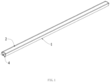
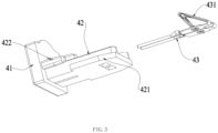
- Figs. 1 to 3 show a first embodiment of a strip-shaped LED-lamp according to the present invention and the following description is particularly focused on the configuration of the end cover of such a strip-shaped LED-lamp.
- the end structure mainly includes a lamp holder 1, a lampshade 2, a light emitting module 3 and an end cover 4.
- the lamp holder 1 has a U-shaped cross-section and comprises a lamp holder base plate 11 with upright sidewalls 12 disposed on both sides of the lamp holder base plate 11 and extending basically perpendicular to the lamp holder base plate 11.
- the lamp holder base plate 11 and the lamp holder sidewall 12 together form a U-shaped mounting port 13 which is open towards the upper end of the lamp holder 1 and an end portion of the lamp holder 1.
- the lamp holder sidewalls 12 each comprise a first slot (groove) 121 and a second slot (groove) 122, each extending in the longitudinal direction of the lamp holder 1 and in parallel with, but spaced apart from, the lamp holder base plate 11.
- the lampshade 2 is mounted on the lamp holder 1.
- the lampshade 2 is of convex shaped and provided with snap-in portions 21 protruding on both sides of the convex central portion of the lamp holder 1 in the width direction, which is parallel to the lamp holder base plate 11.
- the snap-in portions 21 extend in the longitudinal direction, and the snap-in portions 21 are mated with the first slot 121 so that they can be snapped into the first slots 121 and fixedly mounted therein in a positive-fit manner. In this manner, the lampshade 2 and the lamp holder 1 can be connected to each other to form the inner cavity 14 of the strip-shaped lamp.
- the first slot 121 is provided on the two opposite inner sides of the lamp holder sidewalls 12, and the lampshade 2 may be connected to the lamp holder 1 by inserting the snap-in portions 21 into the opposite first slots 121 and sliding the lampshade 2 in the longitudinal direction of the first slots 121 starting from the mounting port 13 of the lamp holder 1.
- the lamp holder 1 is provided with two opposite second slots 122 formed in the two opposite lamp holder sidewalls 12 closer to the lamp holder base plate 11, preferably adjacent to the lamp holder base plate 11.
- the second slots 122 extend in the longitudinal direction of the lamp holder 1 and in parallel with the first slots 121.
- the second slots 122 may be used for accommodating guiding blocks 421 of bracket 42, explained in more detail hereinafter.
- the light emitting module 3 comprises a strip-shaped, rectangular light board 31 and an LED unit 32 disposed on the light board 31. More specifically, a plurality of LED-units 32 may be provided on the light board 31 and distributed at equidistant spacing along the longitudinal direction.
- the light board 31 is provided with an electrically conductive layer 33 at an end portion in the length direction. More specifically, the electrically conductive layer 33 is provided at an end portion of the light board 31, particularly at a center thereof and extending in the length direction of the light board 31, and may be embodied as two gold fingers or gold-plated connecting structures that are insulated against each other, for electrical power supply of the light emitting module 3.
- the electrically conductive layer 33 is provided on the bottom surface of the light board 31.
- the end cover 4 is provided at the end of the lamp holder 1 and includes an outer cover 41, which may be plate-shaped, and a bracket 42 extending perpendicular to the outer cover 41.
- the outer cover 41 is connected or mounted to the end of the lamp holder 1 at the mounting port 13.
- the outer cover 41 and the end of the lamp holder 1 may be connected to each other by means of fasteners, or by means of a plug or socket-type connector or other means of connection.
- the outer cover 41 may be snap-fitted into the mounting port 13 of the lamp holder 1 or mounted in a positive-fit manner to the mounting port 13.
- the outer cover 41 covers the mounting port 13 of the lamp holder 1 and seals the inner cavity 14 of the lamp holder 1 against the environment, to prevent the intrusion of dirt and moisture into the inner cavity.
- Both sides of the bracket 42 may be provided with guiding blocks 421 that are mated to the second slots 122 and configured for insertion and sliding in the second slots 122 via the mounting port 13 along the longitudinal direction of the lamp holder 1.
- the bracket 42 is provided with a resiliently biased terminal 43.
- the resiliently biased terminal 43 and the bracket 42 may be connected to each other by means of a plug-in fastening or a fastener.
- the resiliently biased terminal 43 comprises an overlapping connecting portion 431 forming two contact portions that are configured to be in electric contact with the conductive layers 33 of the light board 31, in particular by abutment with the conductive layers 33.
- the overlapping connecting portion 431 may be a conductive sheet that is bent to a resilient contacting portion of e.g. a triangular profile.
- the outer cover 41 is provided with an interface 411 for electrically connecting the external wiring harness 5 to the resiliently biased terminal 43, i.e., for supplying the light board 31 with an external power via the resiliently biased terminal 43.
- Fig. 3 shows the general configuration of the end cover 4, wherein the resiliently biased terminal 43 may be a one-piece molded structure, and wherein the resiliently biased terminal 43 may be formed with barbs or resilient tongues at fixed positions relative to the bracket 42.
- the lamp holder 1 may be provided with a rib 15 extending in the longitudinal direction and adapted to support or abut against the bottom surface of the light board 31.
- the front end of the rib 15 is preferably spaced apart to the mounting port 13 of the lamp holder 1.
- the sides of the rib 15 may be fixedly connected to the lamp holder sidewalls 12.
- the rib 15 may be a structure integrally molded or extruded in the lamp holder 1 with the lamp holder sidewall 12.
- the rib 15 may be a planar structure, which is used to support the light board 31, and may also serve for dissipating heat away from the light board 31 to the lamp holder 1 by thermal contact.
- the rib 15 may also serve for enhancing the mechanical stability of the lamp holder 1.
- An additional limiting strip 125 may be formed on the side wall 12 of the lamp holder 1, to form a third slot 123 extending in the longitudinal direction, which is formed adjacent to first slot 121.
- the light board 31 may be inserted into the inner cavity 14 of the lamp holder 1 via the opening port 13 along the third slot 123 so that the lateral edges of the light board 31 are accommodated in the third slots 123.
- the light board 31 of the present invention is not provided with patch connectors at both ends, but is mounted on the rib 15, which requires that the bottom surface of the light board 31 opposite to the upper surface with the LED units 32 does not have a protrusion.
- the light board 31 is preferably not provided with a patch connector at the end of the light board 31, and the LED unit 32 does not have a protrusion at its bottom surface.
- a conductive layer 33 is provided on the light board 31 at an end portion thereof (cf. Fig. 2 ), which is contacted via the overlapping connecting portion 431 of the resiliently biased terminal 43.
- the end of the rib 15 is provided with an avoidance opening for the end cover 4 to be mounted into the inner cavity 14 of the lamp holder 1.
- positioning blocks 422 which may be pin-shaped as shown in Fig. 3 , may be provided on both sides of the bracket 42 as shown in Fig. 2 , and corresponding positioning slots 124 may be formed on the sidewalls 12 of the lamp holder 1 to accommodate to the positioning blocks 422 for precisely positioning the bracket 42 and end cover 41.
- the depth of the positioning blocks 422 may be less than that of the guiding blocks 421, and the level (above the bottom end of end cover 41) at which the positioning blocks 422 are provided is a little higher than the bracket 42.
- the lamp holder 1 is provided with the lampshade 2, the light board 31, and the bracket 42 in order from top to bottom.
- the plurality of LED-units 32 is provided at the upper surface of the light board 31 and directed toward the lampshade 2, and the electrically conductive layer 33 is provided at the bottom surface of the light board 31.
- the lampshade 2 and the light board 31 are first installed in the lamp holder 1 by insertion via the mounting port 13, and then the end cover 4 is installed by insertion into the mounting port 13 of the lamp holder 1.
- the guiding blocks 421 of the bracket 42 first enter along the second slots 122 for a certain distance, and then the positioning blocks 422 enter the positioning grooves 124 until the outer cover 41 rests against the end portion of the lamp holder 1 in order to cover and seal the mounting port 13 of lamp holder 1, and the overlapping connection portions 431 of the resiliently biased terminal 43 of the bracket 42 resiliently contact the electrically conductive layer 33 on the bottom surface of light board 31 after installation.
- the outer cover 41 and the bracket 42 may be formed in one piece, so that in the assembly process, the light board 31 and the lampshade 2 are mounted to the lamp holder 1 via the slots 121 and 123, and the resiliently biased terminal 43 provided at the end cover 4 is assembled as a whole at the end portion of the lamp holder 1, which simplifies the assembly steps and facilitates automated production.
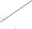
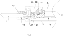
- Figs. 4 to 12 show a second embodiment of a strip-shaped LED-lamp according to the present invention and the following description is particularly focused on the configuration of the end cover of such a strip-shaped LED-lamp.
- the end structure of the strip-shaped lamp mainly includes a lamp holder 1, a lampshade 2, a light-emitting module 3 and an end cover 4.
- the configuration of the lamp holder 1 and end cover 4 is different as compared to the afore-mentioned first embodiment.
- the lamp holder 1 has a U-shaped cross-section and comprises a lamp holder base plate 11 with upright sidewalls 12 disposed on both sides of the lamp holder base plate 11 and extending basically perpendicular to the lamp holder base plate 11.
- the lamp holder base plate 11 and the lamp holder sidewall 12 together form a U-shaped mounting port 13 which is open towards the upper end of the lamp holder 1 and an end portion of the lamp holder 1, which open towards the front end (lateral side of lamp holder 1) and forms a mounting port 13.
- the lamp holder sidewalls 12 each comprise a first slot (groove) 121, which is open towards the upper end of the lamp holder 1, and a second slot (groove) 122, which is open towards the inner cavity of lamp holder 1.
- Each of the slots 121, 122 extend in the longitudinal direction of the lamp holder 1 and in parallel with each other.
- the lampshade 2 is mounted on the lamp holder 1.
- the lampshade 2 is convex shaped and provided with snap-in portions 21 protruding on both sides of the lamp holder 1 at a bottom end thereof and along the width direction.
- the snap-in portions 21 extend in the longitudinal direction of the lampshade 2, and the snap-in portions 21 are installed in conjunction with the first slot 121 so that they can be snapped or inserted into the first slots 121 and fixedly mounted therein in a positive-fit manner. In this manner, the lampshade 2 and the lamp holder 1 can be connected to form the inner cavity 14 of the strip-shaped lamp.
- the profile of the snap-in portions 21 of the lampshade 2 is mated to the profile of the first slots 121, and the snap-in portions 21 are snap-fitted or inserted into the first slots 121, and the size of the entrance of the first slot 121 is smaller than the end surface of the snap-in portion 21, so that the snap-in portions 21 can be slid into the first slots 121 from the open end of the lamp holder 1, i.e. via the mounting port 13, thereby enabling a lateral mounting.
- the snap-in portions 21 can be embedded and positioned at the bottom of the first slots 121 after entering along the opening of the first slots 121.
- the light emitting module 3 is disposed in the inner cavity 14 of lamp holder 1 and includes a light board 31 and a plurality of LED-units 32 disposed on the upper side of light board 31. More specifically, a plurality of LED-units 32 may be provided on the light board 31 and distributed at equidistant spacing along the longitudinal direction.
- the light board 31 is provided with an electrically conductive layer 33 at an end portion in the length direction. More specifically, the electrically conductive layer 33 is provided at an end portion of the light board 31, particularly at a center thereof and extending in the length direction of the light board 31, and may be embodied as two gold fingers or gold-plated connecting structures that are insulated against each other, for electrical power supply of the light emitting module 3.
- the end cover 4 is provided at the end of the lamp holder 1 and includes an outer cover 41, which may be plate-shaped, and a bracket 42 extending perpendicular to the outer cover 41, i.e. in the longitudinal direction of lamp holder 1.
- the outer cover 41 is connected or mounted to the end of the lamp holder 1 at the mounting port 13, to thereby cover the mounting port 13 and seal it against the environment for preventing intrusion of dirt and moisture into the inner cavity 14.
- the outer cover 41 and the end of the lamp holder 1 may be connected to each other by means of fasteners, or by means of a plug or socket-type connector or other means of connection.
- the outer cover 41 may be snap-fitted into the mounting port 13 of the lamp holder 1.
- Both sides of the bracket 42 may be provided with guiding blocks 421 that are mated to the second slots 122 and configured for insertion and sliding in the second slots 122 via the mounting port 13 along the longitudinal direction of the lamp holder 1.
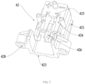
- a limiting block 423 preferably a pair of limiting blocks 423, may be provided at the bottom side of the bracket 42. In the process of inserting the bracket 42 along the second slots 122 in the lamp holder 1, the limiting block 423 finally reaches a limit position when it rests against the lamp holder 1 so that the bracket 42 cannot be inserted beyond this limit position into the lamp holder 1.
- the bracket 42 is provided with a resiliently biased terminal 43.
- the resiliently biased terminal 43 and the bracket 42 may be connected to each other by means of a plug-in fastening or a fastener.
- the resiliently biased terminal 43 comprises an overlapping connecting portion 431 forming two contact portions that are configured to electrically contact the conductive layers 33 of the light board 31 by abutment.
- the overlapping connecting portion 431 may be a conductive sheet that is bent to a resilient contacting portion of e.g. a triangular profile.
- the outer cover 41 is provided with an interface 411 such as a plug or socket connector, for electrically connecting the external wiring harness 5 to the resiliently biased terminal 43, i.e., for supplying the light board 31 with an external power via the resiliently biased terminal 43.
- a pair of limiting strips 125 extends basically perpendicular to the lamp holder base plate 11, spaced apart to the lamp holder sidewalls 12 to form the first slots 121.
- a protrusion is formed projecting into the inner cavity 14 of lamp holder 1, basically in parallel to the lamp holder base plate 11 to thereby form the second slots 122.
- the two lateral edges of the light board 31 can be inserted into the second slots 122 by insertion via the mounting port 13 and sliding along the longitudinal direction, and after assembly the bottom surface of the light board 31 rests against the lamp holder base plate 11. That is, both the light board 31 and the bracket 42 are mounted on the lamp holder 1 by means of the second slot 122, and for assembly, it is necessary to mount the light board 31 first and then the bracket 42.
- the resiliently biased terminal 43 is connected to the external wiring harness 5, e.g. via a plug or socket connector, and passes through the end of the bracket 42 and is fixedly mounted on the bracket 42.
- An accommodation opening 424 is provided in the bracket 42 near the side of the head to be adapted to fit with the resiliently biased terminal 43, and a stopper 425 is provided at the end of the accommodation opening 424 for limiting the longitudinal position of resiliently biased terminal 43, and a stopper 425 is provided in the middle part of the bracket 42 adjacent to the accommodation opening 424 for restricting the resiliently biased terminal 43 and in particular for separating the two contact fingers of the resiliently biased terminal 43 to prevent short-circuiting.
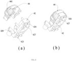
- the resiliently biased terminal 43 is first made to pass into the holding port 424 from the top down, as shown in Fig. 8(a) , until the resiliently biased terminal 43 contacts the end portion of the holding port 424, and then it is turned over or pivoted downward by about 90 degrees, and the stopper 425 may be pressed downwardly to hold down the end portion of the resiliently biased terminal 43.
- the external wiring harness 5 is installed between the limiting post 426 from the top down, and is then fixed by the central limiting post 426 in the middle of the bracket 42 and adjacent to the holding port 424.
- the central limiting post 426 may be provided with an inverted buckling portion to limit the external wiring harness 5, particularly in a positive-fit manner.
- the resiliently biased terminals 43 do not flip relative to each other, for preventing in particular a short-circuiting, and the external wiring harness 5 does not detach from the bracket 42 after the installation is completed, thereby achieving a fixing effect.
- the LED-units 32 and the conductive layer 33 on the light board 31 are provided on the upper side of the light board 31.
- the width of the conductive layer 33 provided at the end portion of the light board 31 is smaller than the width of the middle portion of the light board 31.
- the LED-unit 32 are provided on the light board 31 in the area starting from the conductive layer 33 to the opposite end portion of the light board 31 if viewed in the longitudinal direction.
- the overlapping connecting portions 431 of the resiliently biased terminal 43 are provided and configured such that they pass downward through the holding port 424 and abut against the contacting fingers formed by conductive layer 33 of the light board 31 for electric power supply.
- a holding groove may be provided in the head of the bracket 42 which is suitable for holding the end portion of the light board 31. More specifically, the head of the bracket 42 may be provided with an accommodation slot 427 (cf. Figs. 9a and 9b ) suitable for accommodating an end portion of the light board 31, for defining the level of the end portion of the light board 31 and ensure a reliable electrical contact between the overlapping connecting portions 431 of the resiliently biased terminal 43 and the contact fingers formed by the conductive layer 33 on the light board 31.
- the accommodation slot 427 may be formed on a bottom side of the bracket 42, and the accommodation slot 427 is connected to the accommodation opening 424.
- the bracket 42 and the outer cover 41 may be provided with an anti-pull block 46, which is provided outside the external wiring harness 5 and is fixedly connected to the external wiring harness 5.
- the fixed connection of the anti-pull block 46 and the external wiring harness 5 may be adhesive fixing, extruding fixing, ultrasonic welding, etc.
- the anti-pull block 46 abuts against the outer cover 41, the outer wiring passes through the interface 411 of the outer cover 41 and is then fixedly connected to the anti-pull block 46.
- the anti-pull block 46 will be pressed against the outer cover 41 to prevent further outward movement, thereby protecting the connection structure of the external wiring harness 5 and the resiliently biased terminal 43, and achieving the effect of anti-pull protection.
- the end cover 4 may also include a blocking head 44, which is provided with a sealing ring 441 and is matingly connected to the bracket 42 and has an interference fit with the inner wall of the lampshade 2. As shown in Fig. 9 , the blocking head 44 is mounted on the upper side of the bracket 42 and is positioned for mounting through a post hole structure. Instead of a single sealing ring 441 there may be provided a plurality of sealing rings to further improve the sealing effect, and when the blocking head 44 is accessed or mounted to the lampshade 2, the sealing is achieved by the sealing ring 441 and the inner wall of the lampshade 2 resiliently contacting each other.
- the blocking head 44 may optionally be made of an elastic material such as a soft rubber for this purpose.
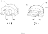
- the outer cover 41 is provided with a mounting recess 412 adapted to the bracket 42 at an end opposite the bracket 42, as shown in Fig. 10b .
- the outer cover 41 may also be provided with an accommodation groove (slot) 413 adapted to the anti-pull block 46.
- the outer cover 41 may be provided with a positioning post 414 or a pair of positioning posts 414 directed towards the bracket 42, and the end of the bracket 42 may be provided with a positioning hole 428 corresponding to the positioning post 414, so that the bracket 42 can be positioned in the outer cover 41 by the cooperation of the at least one positioning post 414 and the corresponding positioning hole 428.
- the outer cover 41 During assembly, when the outer cover 41 approaches the end of the lamp holder 1, the outer cover 41 first accommodates the anti-pull block 46, then abuts against the bracket 42, and then fits against the lamp holder 1 for assembly, as shown in Fig. 11 .
- the outer cover 41 and the lamp holder 1 may be connected to each other by fasteners, for example by screws 45.
- the outer cover 41 may be provided with mounting holes 415 corresponding to the screws 45, and a threaded port may be provided at the opening of the second slot 122 of the lamp holder 1, and the outer cover 41 may be mounted at the end of the lamp holder 1 by means of the screws 45 extending along the mounting holes 415.
- the resiliently biased terminal 43 is fixedly mounted on the bracket 42 after connecting the external wiring harness 5.
- the anti-pull block 46 is fixed on the external wiring harness 5
- the blocking head 44 is mounted on the bracket 42
- the light emitting module 3 and the lampshade 2 are mounted in the lamp holder 1.
- the outer cover 41 is connected to the external wiring harness 5 and is mounted against the anti-pull block 46 towards the end portion of the lamp holder 1, and the connection is tightly fastened after installation. Subsequently, a connection terminal is assembled at the other end of the external wiring harness 5.
- the outer cover 41 may be provided with a glue injection hole 416, and after installation of the outer cover 41 a glue may be injected via the glue injection hole 416 into a glue injection cavity 16 formed between the end cover 4 and the blocking head 44, the lamp holder 1, and the lampshade 2.
- a waterproof structure can be accomplished at the end of the lamp holder 1 after the glue injection.
- the glue injection may be performed at the bottom of the first slot 121 for sealing to accomplish a waterproofing between the lampshade 2 and the lamp holder 1.
- the present invention also provides an easy-to-assemble strip-shaped light comprising a lamp holder 1, a lampshade 2, a light-emitting module 3 and an end cover 4 provided at the end of the lamp holder 1.
Landscapes
- Engineering & Computer Science (AREA)
- General Engineering & Computer Science (AREA)
- Non-Portable Lighting Devices Or Systems Thereof (AREA)
- Fastening Of Light Sources Or Lamp Holders (AREA)
- Arrangement Of Elements, Cooling, Sealing, Or The Like Of Lighting Devices (AREA)
Applications Claiming Priority (1)
| Application Number | Priority Date | Filing Date | Title |
|---|---|---|---|
| CN202211210967.3A CN115479224A (zh) | 2022-09-30 | 2022-09-30 | 一种条形灯端部结构 |
Publications (2)
| Publication Number | Publication Date |
|---|---|
| EP4345366A1 true EP4345366A1 (de) | 2024-04-03 |
| EP4345366B1 EP4345366B1 (de) | 2026-05-06 |
Family
ID=84394148
Family Applications (1)
| Application Number | Title | Priority Date | Filing Date |
|---|---|---|---|
| EP23199623.2A Active EP4345366B1 (de) | 2022-09-30 | 2023-09-26 | Streifenförmige lampe und endkappe für eine derartige streifenförmige lampe |
Country Status (2)
| Country | Link |
|---|---|
| EP (1) | EP4345366B1 (de) |
| CN (1) | CN115479224A (de) |
Cited By (1)
| Publication number | Priority date | Publication date | Assignee | Title |
|---|---|---|---|---|
| TWI877007B (zh) * | 2024-05-22 | 2025-03-11 | 接觸燈飾有限公司 | 燈具 |
Families Citing this family (1)
| Publication number | Priority date | Publication date | Assignee | Title |
|---|---|---|---|---|
| EP4575310A1 (de) * | 2023-12-19 | 2025-06-25 | Siteco GmbH | Leuchte mit toleranz- und wärmeausdehnungsunabhängiger stirnwandlösung |
Citations (3)
| Publication number | Priority date | Publication date | Assignee | Title |
|---|---|---|---|---|
| US20140362574A1 (en) * | 2013-06-05 | 2014-12-11 | Brian Barrett | Modular light emitting diode lighting system |
| EP4033145A1 (de) * | 2021-01-26 | 2022-07-27 | Self Electronics Co., Ltd. | Wasserdichtes streifenlicht, das die automatisierte herstellung erleichtert |
| CN217356571U (zh) * | 2022-04-02 | 2022-09-02 | 广东悍高家居科技有限公司 | 一种线条灯 |
Family Cites Families (14)
| Publication number | Priority date | Publication date | Assignee | Title |
|---|---|---|---|---|
| CN201739816U (zh) * | 2010-06-04 | 2011-02-09 | 天津津亚电子有限公司 | 一种发光二极管灯条 |
| CN102269348A (zh) * | 2010-06-04 | 2011-12-07 | 天津津亚电子有限公司 | 一种发光二极管灯条 |
| CN202048417U (zh) * | 2011-04-08 | 2011-11-23 | 东莞市光宇实业有限公司 | 一种led灯管 |
| CN104168731A (zh) * | 2014-08-05 | 2014-11-26 | 海信容声(广东)冰箱有限公司 | 一种电器盒 |
| CN104728953A (zh) * | 2015-02-14 | 2015-06-24 | 宁波奥克斯空调有限公司 | 一种空调器电控盒 |
| CN204739508U (zh) * | 2015-05-25 | 2015-11-04 | 乐清市沃达蒙照明电器有限公司 | 一种led三防灯 |
| CN204756636U (zh) * | 2015-07-22 | 2015-11-11 | 四川东顺光电有限公司 | 一种led棱角装饰照明灯 |
| CN206268842U (zh) * | 2016-12-15 | 2017-06-20 | 深圳市科纳实业有限公司 | Led三防灯 |
| CN208457629U (zh) * | 2018-06-08 | 2019-02-01 | 广东奔跑创造照明科技有限公司 | 一种对接无阴影的线型灯具 |
| CN208886454U (zh) * | 2018-10-31 | 2019-05-21 | 柯赛科技(深圳)有限公司 | 一种便于安装的led线条灯 |
| CN210398624U (zh) * | 2019-10-29 | 2020-04-24 | 深圳市云镜照明科技有限公司 | 一种长条形ffu龙骨吸顶安装灯具 |
| CN211146154U (zh) * | 2019-12-19 | 2020-07-31 | 欧普照明股份有限公司 | 线条灯以及线条灯系统 |
| CN112283602A (zh) * | 2020-10-28 | 2021-01-29 | 赛尔富电子有限公司 | 一种适合自动化生产的灯具 |
| CN213394741U (zh) * | 2020-11-23 | 2021-06-08 | 中山市乐道光电科技有限公司 | 一种密封性好的线条灯 |
-
2022
- 2022-09-30 CN CN202211210967.3A patent/CN115479224A/zh active Pending
-
2023
- 2023-09-26 EP EP23199623.2A patent/EP4345366B1/de active Active
Patent Citations (3)
| Publication number | Priority date | Publication date | Assignee | Title |
|---|---|---|---|---|
| US20140362574A1 (en) * | 2013-06-05 | 2014-12-11 | Brian Barrett | Modular light emitting diode lighting system |
| EP4033145A1 (de) * | 2021-01-26 | 2022-07-27 | Self Electronics Co., Ltd. | Wasserdichtes streifenlicht, das die automatisierte herstellung erleichtert |
| CN217356571U (zh) * | 2022-04-02 | 2022-09-02 | 广东悍高家居科技有限公司 | 一种线条灯 |
Cited By (1)
| Publication number | Priority date | Publication date | Assignee | Title |
|---|---|---|---|---|
| TWI877007B (zh) * | 2024-05-22 | 2025-03-11 | 接觸燈飾有限公司 | 燈具 |
Also Published As
| Publication number | Publication date |
|---|---|
| CN115479224A (zh) | 2022-12-16 |
| EP4345366B1 (de) | 2026-05-06 |
Similar Documents
| Publication | Publication Date | Title |
|---|---|---|
| US8342733B2 (en) | LED lighting assemblies | |
| US7429186B2 (en) | Flexible high-power LED lighting system | |
| KR101448700B1 (ko) | 직관형 led 램프, 램프 소켓 세트 및 조명 기구 | |
| EP4345366B1 (de) | Streifenförmige lampe und endkappe für eine derartige streifenförmige lampe | |
| CN103906971B (zh) | 用于保持至少一个平面的面光灯的保持元件、由多个灯座和多个长的保持体构成的成套设备和发光器 | |
| US9153882B2 (en) | Connector having a cylindrical section with a contact connected to an electrical wire therein | |
| CN203810108U (zh) | 直管灯及照明装置 | |
| CN103415740B (zh) | 用于灯具的oled发光体 | |
| US7309252B2 (en) | Low profile surface mount connector | |
| US20110248631A1 (en) | Led lamp set | |
| EP2400214A2 (de) | Beleuchtungsvorrichtung | |
| US20090021951A1 (en) | Watertight led lamp | |
| WO2009099549A1 (en) | Led module and interconnection system | |
| JP2006012859A (ja) | 表示・照明装置 | |
| WO2008073690A1 (en) | Led light engine and method of manufacturing | |
| CN110043812A (zh) | 一种互联灯具 | |
| CN109812743B (zh) | 照明装置及吸顶灯 | |
| CN209977721U (zh) | 一种互联灯具 | |
| KR102191054B1 (ko) | 엘이디 조명등의 전기적 연결장치 | |
| KR100831048B1 (ko) | 엘이디 회로 기판 서포트 및 이를 포함하는 엘이디 모듈조립체 | |
| CN204254319U (zh) | 发光装置 | |
| CN207146080U (zh) | 照明装置 | |
| CN218032768U (zh) | 一种用于线槽灯的led灯带 | |
| CN223954017U (zh) | 灯具的拼接结构 | |
| CN214405978U (zh) | 灯板连接器 |
Legal Events
| Date | Code | Title | Description |
|---|---|---|---|
| PUAI | Public reference made under article 153(3) epc to a published international application that has entered the european phase |
Free format text: ORIGINAL CODE: 0009012 |
|
| STAA | Information on the status of an ep patent application or granted ep patent |
Free format text: STATUS: THE APPLICATION HAS BEEN PUBLISHED |
|
| AK | Designated contracting states |
Kind code of ref document: A1 Designated state(s): AL AT BE BG CH CY CZ DE DK EE ES FI FR GB GR HR HU IE IS IT LI LT LU LV MC ME MK MT NL NO PL PT RO RS SE SI SK SM TR |
|
| STAA | Information on the status of an ep patent application or granted ep patent |
Free format text: STATUS: REQUEST FOR EXAMINATION WAS MADE |
|
| 17P | Request for examination filed |
Effective date: 20240519 |
|
| RBV | Designated contracting states (corrected) |
Designated state(s): AL AT BE BG CH CY CZ DE DK EE ES FI FR GB GR HR HU IE IS IT LI LT LU LV MC ME MK MT NL NO PL PT RO RS SE SI SK SM TR |
|
| STAA | Information on the status of an ep patent application or granted ep patent |
Free format text: STATUS: EXAMINATION IS IN PROGRESS |
|
| 17Q | First examination report despatched |
Effective date: 20251016 |
|
| GRAP | Despatch of communication of intention to grant a patent |
Free format text: ORIGINAL CODE: EPIDOSNIGR1 |
|
| STAA | Information on the status of an ep patent application or granted ep patent |
Free format text: STATUS: GRANT OF PATENT IS INTENDED |
|
| RIC1 | Information provided on ipc code assigned before grant |
Ipc: F21S 4/20 20160101AFI20260204BHEP Ipc: F21V 29/503 20150101ALI20260204BHEP Ipc: F21V 23/00 20150101ALI20260204BHEP Ipc: F21V 23/06 20060101ALI20260204BHEP Ipc: F21V 15/015 20060101ALI20260204BHEP Ipc: F21V 31/00 20060101ALI20260204BHEP Ipc: F21V 15/01 20060101ALN20260204BHEP Ipc: F21V 17/10 20060101ALN20260204BHEP Ipc: F21V 19/00 20060101ALN20260204BHEP Ipc: F21Y 103/10 20160101ALN20260204BHEP Ipc: F21Y 115/10 20160101ALN20260204BHEP |
|
| INTG | Intention to grant announced |
Effective date: 20260224 |
|
| GRAS | Grant fee paid |
Free format text: ORIGINAL CODE: EPIDOSNIGR3 |
|
| GRAA | (expected) grant |
Free format text: ORIGINAL CODE: 0009210 |
|
| STAA | Information on the status of an ep patent application or granted ep patent |
Free format text: STATUS: THE PATENT HAS BEEN GRANTED |
|
| AK | Designated contracting states |
Kind code of ref document: B1 Designated state(s): AL AT BE BG CH CY CZ DE DK EE ES FI FR GB GR HR HU IE IS IT LI LT LU LV MC ME MK MT NL NO PL PT RO RS SE SI SK SM TR |
|
| REG | Reference to a national code |
Ref country code: CH Ref legal event code: F10 Free format text: ST27 STATUS EVENT CODE: U-0-0-F10-F00 (AS PROVIDED BY THE NATIONAL OFFICE) Effective date: 20260506 Ref country code: GB Ref legal event code: FG4D |