EP4345371A1 - Systèmes et procédés d'éclairage utilisant des diodes thermiques pour la gestion de la chaleur - Google Patents
Systèmes et procédés d'éclairage utilisant des diodes thermiques pour la gestion de la chaleur Download PDFInfo
- Publication number
- EP4345371A1 EP4345371A1 EP22198578.1A EP22198578A EP4345371A1 EP 4345371 A1 EP4345371 A1 EP 4345371A1 EP 22198578 A EP22198578 A EP 22198578A EP 4345371 A1 EP4345371 A1 EP 4345371A1
- Authority
- EP
- European Patent Office
- Prior art keywords
- condenser
- evaporator
- led
- driver
- thermal diode
- Prior art date
- Legal status (The legal status is an assumption and is not a legal conclusion. Google has not performed a legal analysis and makes no representation as to the accuracy of the status listed.)
- Ceased
Links
Images



Classifications
-
- F—MECHANICAL ENGINEERING; LIGHTING; HEATING; WEAPONS; BLASTING
- F21—LIGHTING
- F21V—FUNCTIONAL FEATURES OR DETAILS OF LIGHTING DEVICES OR SYSTEMS THEREOF; STRUCTURAL COMBINATIONS OF LIGHTING DEVICES WITH OTHER ARTICLES, NOT OTHERWISE PROVIDED FOR
- F21V29/00—Protecting lighting devices from thermal damage; Cooling or heating arrangements specially adapted for lighting devices or systems
- F21V29/10—Arrangement of heat-generating components to reduce thermal damage, e.g. by distancing heat-generating components from other components to be protected
-
- F—MECHANICAL ENGINEERING; LIGHTING; HEATING; WEAPONS; BLASTING
- F21—LIGHTING
- F21V—FUNCTIONAL FEATURES OR DETAILS OF LIGHTING DEVICES OR SYSTEMS THEREOF; STRUCTURAL COMBINATIONS OF LIGHTING DEVICES WITH OTHER ARTICLES, NOT OTHERWISE PROVIDED FOR
- F21V29/00—Protecting lighting devices from thermal damage; Cooling or heating arrangements specially adapted for lighting devices or systems
- F21V29/15—Thermal insulation
-
- F—MECHANICAL ENGINEERING; LIGHTING; HEATING; WEAPONS; BLASTING
- F21—LIGHTING
- F21V—FUNCTIONAL FEATURES OR DETAILS OF LIGHTING DEVICES OR SYSTEMS THEREOF; STRUCTURAL COMBINATIONS OF LIGHTING DEVICES WITH OTHER ARTICLES, NOT OTHERWISE PROVIDED FOR
- F21V29/00—Protecting lighting devices from thermal damage; Cooling or heating arrangements specially adapted for lighting devices or systems
- F21V29/50—Cooling arrangements
- F21V29/51—Cooling arrangements using condensation or evaporation of a fluid, e.g. heat pipes
-
- F—MECHANICAL ENGINEERING; LIGHTING; HEATING; WEAPONS; BLASTING
- F28—HEAT EXCHANGE IN GENERAL
- F28D—HEAT-EXCHANGE APPARATUS, NOT PROVIDED FOR IN ANOTHER SUBCLASS, IN WHICH THE HEAT-EXCHANGE MEDIA DO NOT COME INTO DIRECT CONTACT
- F28D15/00—Heat-exchange apparatus with the intermediate heat-transfer medium in closed tubes passing into or through the conduit walls ; Heat-exchange apparatus employing intermediate heat-transfer medium or bodies
- F28D15/02—Heat-exchange apparatus with the intermediate heat-transfer medium in closed tubes passing into or through the conduit walls ; Heat-exchange apparatus employing intermediate heat-transfer medium or bodies in which the medium condenses and evaporates, e.g. heat pipes
- F28D15/025—Heat-exchange apparatus with the intermediate heat-transfer medium in closed tubes passing into or through the conduit walls ; Heat-exchange apparatus employing intermediate heat-transfer medium or bodies in which the medium condenses and evaporates, e.g. heat pipes having non-capillary condensate return means
-
- H—ELECTRICITY
- H10—SEMICONDUCTOR DEVICES; ELECTRIC SOLID-STATE DEVICES NOT OTHERWISE PROVIDED FOR
- H10H—INORGANIC LIGHT-EMITTING SEMICONDUCTOR DEVICES HAVING POTENTIAL BARRIERS
- H10H20/00—Individual inorganic light-emitting semiconductor devices having potential barriers, e.g. light-emitting diodes [LED]
- H10H20/80—Constructional details
- H10H20/85—Packages
- H10H20/858—Means for heat extraction or cooling
- H10H20/8586—Means for heat extraction or cooling comprising fluids, e.g. heat-pipes
-
- H—ELECTRICITY
- H10—SEMICONDUCTOR DEVICES; ELECTRIC SOLID-STATE DEVICES NOT OTHERWISE PROVIDED FOR
- H10W—GENERIC PACKAGES, INTERCONNECTIONS, CONNECTORS OR OTHER CONSTRUCTIONAL DETAILS OF DEVICES COVERED BY CLASS H10
- H10W40/00—Arrangements for thermal protection or thermal control
- H10W40/70—Fillings or auxiliary members in containers or in encapsulations for thermal protection or control
- H10W40/73—Fillings or auxiliary members in containers or in encapsulations for thermal protection or control for cooling by change of state
Definitions
- the present invention is directed generally to heat management of lighting systems. More particularly, various inventive methods, systems and apparatus disclosed herein relate to lighting systems and methods utilizing thermal diodes.
- LEDs light-emitting diodes
- Functional advantages and benefits of LEDs include high energy conversion and optical efficiency, durability, lower operating costs, and many others.
- Recent advances in light-emitting diode (LED) technology have provided efficient and robust full-spectrum lighting sources that enable a variety of lighting effects in many applications.
- Some of the fixtures embodying these sources feature a lighting module, including one or more LEDs capable of producing different colors, e.g. red, green, and blue, as well as a processor for independently controlling the output of the LEDs in order to generate a variety of colors and color-changing lighting effects.
- a lighting fixture may include a driver, transformer, surge module and an illuminating circuit to perform different functions.
- the type and specification of these components depends on the environmental conditions, applications, and user experiences in which it is to be installed.
- LEDs offering higher energy savings and lesser maintenance over their life span.
- the life span of LEDs largely depends on their operating temperature, where higher operating temperatures lower the life span of LEDs.
- the efficiency of LEDs has significantly increased, which in turn has decreased the total heat generation from the light source.
- thermal management of lighting fixtures is of great importance for the development of LED-based lighting systems.
- Typical methods for thermal management of electronic devices employ heat sinks, heat pipes, vapor chambers, absorption systems and/or thermal diodes.
- Diodes are devices that conduct heat more efficiently in one direction, the forward mode, as compared to the other direction, the reverse mode.
- Thermal diodes employed in current devices are typically solid-state or phase-change thermal diodes. Solid state devices are thermal property dependent devices with diodicity nearer to 1. In turn, phase change thermal diodes utilize latent heat of vaporization in the forward mode and thus have diodicity ranging from 10 to 100.
- thermosyphons are an example of phase change thermal diodes.
- Thermosyphons operate based on buoyant convection and are usually composed of vertically oriented hollow containers that are partially filled with liquid and transfer heat through the phase change of the liquid to the gaseous state.
- heat pipes utilize an evaporator section and a condenser having a wick structure, which condenses vapor and transfers the condensate to the evaporator section. Heat pipes have diodicity of -100.
- jumping droplet thermal diodes utilize microscopic condensate that are propelled several millimeters into the air during coalescence events by a superhydrophobic nanostructure. The diodicity of jumping droplet thermal diodes is approximately -100.
- Lighting fixtures utilizing the above-described thermal management devices have major drawbacks.
- the thermal management devices are excessively direction dependent and/or have low reliability due to the materials used or to the fragility of the structures used.
- the performance of thermosyphons strongly depends upon gravity and orientation due to their structure and reliance on buoyant convection.
- Heat pipes essentially provide a one-dimensional heat transfer that is ineffective in 3D systems.
- arrays of heat pipes can be used to alleviate this problem to some extent, their use adds additional complexity and size, and provides a cost in diodicity.
- the nanostructure of jumping thermal diodes is less durable and causes flooding after prolonged exposure.
- Embodiments of the present application can address these problems by providing a lighting system with a thermal management device that is durable and capable of being used in a variety of orientations, and manages heat in a way that permits a compact structure.
- the heat management device permits coupling of an LED(s) on one side of the device and of other electronic components on the other side of the device such that heat is efficiently transferred to the ambient while at the same time ensuring that both the LED(s) and the electronic components are effectively shielded from each other.
- the LED(s) are effectively shielded from heat generated by the electronic components at the other side of the thermal management device, and the electronic components are effectively shielded from heat generated by the LED(s).
- One exemplary embodiment is directed to a lighting system including at least one LED, a driver configured to power and drive the LED(s) and a droplet thermal diode.
- the diode includes a smooth hydrophobic condenser, an evaporator and a fluid medium disposed between the condenser and the evaporator, where the condenser is spaced 1-500 ⁇ m from the evaporator and where the driver and the LED(s) are oppositely coupled to the thermal diode at opposing sides of the fluid medium.
- the driver is coupled to the condenser and the LED(s) is coupled to the evaporator.
- the evaporator comprises a microchannel wick structure drilled into a surface of the evaporator disposed in a chamber including the fluid medium.
- the condenser comprises graphene or a grafted polymer on a surface of the condenser disposed in a chamber including the fluid medium.
- the condenser can comprise a graphene monolayer on the surface of the condenser.
- the total heat reaching the LED(s) from the driver is less than 5% of the total heat input to the thermal diode by the LED(s).
- the total heat input into the thermal diode by the driver is primarily dissipated out of the thermal diode by the condenser.
- Another exemplary embodiment is directed to a method for producing a lighting system employing a droplet thermal diode for heat management.
- the method includes preparing an evaporator of the thermal diode, preparing a smooth hydrophobic condenser of the thermal diode and conjoining the evaporator and the condenser with a fluid medium disposed between the condenser and the evaporator such that the condenser is spaced 1-500 ⁇ m from the evaporator.
- the method further includes coupling at least one LED to the thermal diode, and coupling a driver, configured to power and drive the LED(s), to the thermal diode such that the driver and the LED(s) are oppositely coupled to the thermal diode at opposing sides of the fluid medium.
- the preparing the evaporator comprises drilling a microchannel wick structure into a surface of the evaporator.
- the preparing the smooth hydrophobic condenser comprises depositing a graphene or grafted polymer layer on a surface of the smooth hydrophobic condenser.
- the preparing the smooth hydrophobic condenser can comprise depositing a graphene monolayer on the surface of the smooth hydrophobic condenser.
- the conjoining comprises providing a gasket between the evaporator and the condenser to form a chamber between the evaporator and the condenser, and filling the chamber with the fluid medium.
- the conjoining can comprise compressing the evaporator and the condenser so that the condenser is spaced 1-500 ⁇ m from the evaporator.
- the method comprises determining a liquid filler ratio based on heat load imposed by the LED(s), where the filling comprises filling the chamber with an amount of a liquid form of the fluid medium that is determined based on the determined liquid filler ratio.
- the coupling the driver comprises coupling the driver to the condenser.
- the coupling the LED(s) comprises coupling the LED(s) to the evaporator.
- the term "LED” should be understood to include any electroluminescent diode or other type of carrier injection/junction-based system that is capable of generating radiation in response to an electric signal.
- the term LED includes, but is not limited to, various semiconductor-based structures that emit light in response to current, light emitting polymers, organic light emitting diodes (OLEDs), electroluminescent strips, and the like.
- the term LED refers to light emitting diodes of all types (including semi-conductor and organic light emitting diodes) that may be configured to generate radiation in one or more of the infrared spectrum, ultraviolet spectrum, and various portions of the visible spectrum (generally including radiation wavelengths from approximately 400 nanometers to approximately 700 nanometers).
- LEDs include, but are not limited to, various types of infrared LEDs, ultraviolet LEDs, red LEDs, blue LEDs, green LEDs, yellow LEDs, amber LEDs, orange LEDs, and white LEDs (discussed further below). It also should be appreciated that LEDs may be configured and/or controlled to generate radiation having various bandwidths (e.g., full widths at half maximum or FWHM) for a given spectrum (e.g., narrow bandwidth, broad bandwidth), and a variety of dominant wavelengths within a given general color categorization.
- bandwidths e.g., full widths at half maximum or FWHM
- an LED configured to generate essentially white light may include a number of dies which respectively emit different spectra of electroluminescence that, in combination, mix to form essentially white light.
- a white light LED may be associated with a phosphor material that converts electroluminescence having a first spectrum to a different second spectrum.
- electroluminescence having a relatively short wavelength and narrow bandwidth spectrum "pumps" the phosphor material, which in turn radiates longer wavelength radiation having a somewhat broader spectrum.
- an LED does not limit the physical and/or electrical package type of an LED.
- an LED may refer to a single light emitting device having multiple dies that are configured to respectively emit different spectra of radiation (e.g., that may or may not be individually controllable).
- an LED may be associated with a phosphor that is considered as an integral part of the LED (e.g., some types of white LEDs).
- the term LED may refer to packaged LEDs, non-packaged LEDs, surface mount LEDs, chip-on-board LEDs, T-package mount LEDs, radial package LEDs, power package LEDs, LEDs including some type of encasement and/or optical element (e.g., a diffusing lens), etc.
- light source should be understood to refer to any one or more of a variety of radiation sources, including, but not limited to, LED-based sources (including one or more LEDs as defined above).
- a given light source may be configured to generate electromagnetic radiation within the visible spectrum, outside the visible spectrum, or a combination of both.
- a light source may include as an integral component one or more filters (e.g., color filters), lenses, or other optical components.
- filters e.g., color filters
- light sources may be configured for a variety of applications, including, but not limited to, indication, display, and/or illumination.
- An "illumination source” is a light source that is particularly configured to generate radiation having a sufficient intensity to effectively illuminate an interior or exterior space.
- sufficient intensity refers to sufficient radiant power in the visible spectrum generated in the space or environment (the unit “lumens” often is employed to represent the total light output from a light source in all directions, in terms of radiant power or "luminous flux”) to provide ambient illumination (i.e., light that may be perceived indirectly and that may be, for example, reflected off of one or more of a variety of intervening surfaces before being perceived in whole or in part).
- spectrum should be understood to refer to any one or more frequencies (or wavelengths) of radiation produced by one or more light sources. Accordingly, the term “spectrum” refers to frequencies (or wavelengths) not only in the visible range, but also frequencies (or wavelengths) in the infrared, ultraviolet, and other areas of the overall electromagnetic spectrum. Also, a given spectrum may have a relatively narrow bandwidth (e.g., a FWHM having essentially few frequency or wavelength components) or a relatively wide bandwidth (several frequency or wavelength components having various relative strengths). It should also be appreciated that a given spectrum may be the result of a mixing of two or more other spectra (e.g., mixing radiation respectively emitted from multiple light sources).
- light fixture is used herein to refer to an implementation or arrangement of one or more lighting units in a particular form factor, assembly, or package.
- lighting unit is used herein to refer to an apparatus including one or more light sources of same or different types.
- a given lighting unit may have any one of a variety of mounting arrangements for the light source(s), enclosure/housing arrangements and shapes, and/or electrical and mechanical connection configurations. Additionally, a given lighting unit optionally may be associated with (e.g., include, be coupled to and/or packaged together with) various other components (e.g., control circuitry) relating to the operation of the light source(s).
- a lighting unit in accordance with embodiments of the present application can include an LED-based lighting unit and/or a multi-channel lighting unit.
- An "LED-based lighting unit” refers to a lighting unit that includes one or more LED-based light sources as discussed above, alone or in combination with other non LED-based light sources.
- a “multi-channel” lighting unit refers to an LED-based or non LED-based lighting unit that includes at least two light sources configured to respectively generate different spectrums of radiation, wherein each different source spectrum may be referred to as a "channel" of the multi-channel lighting unit.
- controller is used herein generally to describe various apparatus relating to the operation of one or more light sources.
- a controller can be implemented in numerous ways (e.g., such as with dedicated hardware) to perform various functions discussed herein.
- a "processor” is one example of a controller which employs one or more microprocessors that may be programmed using software (e.g., microcode) to perform various functions discussed herein.
- a controller may be implemented with or without employing a processor, and also may be implemented as a combination of dedicated hardware to perform some functions and a processor (e.g., one or more programmed microprocessors and associated circuitry) to perform other functions.
- controller components examples include, but are not limited to, conventional microprocessors, application specific integrated circuits (ASICs), and field-programmable gate arrays (FPGAs).
- a processor or controller may be associated with one or more storage media (generically referred to herein as "memory,” e.g., volatile and non-volatile computer memory such as RAM, PROM, EPROM, and EEPROM, floppy disks, compact disks, optical disks, magnetic tape, etc.).
- the storage media may be encoded with one or more programs that, when executed on one or more processors and/or controllers, perform at least some of the functions discussed herein.
- program or “computer program” are used herein in a generic sense to refer to any type of computer code (e.g., software or microcode) that can be employed to program one or more processors or controllers.
- addressable is used herein to refer to a device (e.g., a light source in general, a lighting unit or fixture, a controller or processor associated with one or more light sources or lighting units, other non-lighting related devices, etc.) that is configured to receive information (e.g., data) intended for multiple devices, including itself, and to selectively respond to particular information intended for it.
- information e.g., data
- addressable often is used in connection with a networked environment (or a "network,” discussed further below), in which multiple devices are coupled together via some communications medium or media.
- one or more devices coupled to a network may serve as a controller for one or more other devices coupled to the network (e.g., in a master/slave relationship).
- a networked environment may include one or more dedicated controllers that are configured to control one or more of the devices coupled to the network.
- multiple devices coupled to the network each may have access to data that is present on the communications medium or media; however, a given device may be "addressable" in that it is configured to selectively exchange data with (i.e., receive data from and/or transmit data to) the network, based, for example, on one or more particular identifiers (e.g., "addresses") assigned to it.
- network refers to any interconnection of two or more devices (including controllers or processors) that facilitates the transport of information (e.g. for device control, data storage, data exchange, etc.) between any two or more devices and/or among multiple devices coupled to the network.
- networks suitable for interconnecting multiple devices may include any of a variety of network topologies and employ any of a variety of communication protocols.
- any one connection between two devices may represent a dedicated connection between the two systems, or alternatively a non-dedicated connection.
- non-dedicated connection may carry information not necessarily intended for either of the two devices (e.g., an open network connection).
- various networks of devices as discussed herein may employ one or more wireless, wire/cable, and/or fiber optic links to facilitate information transport throughout the network.
- Embodiments of the present application are directed to lighting systems and methods employing thermal diodes to manage heat within the systems.
- the lighting systems and thermal diodes employed therein are both durable and usable in a variety of orientations, and provide heat management in a way that enables a compact structure for the system.
- the heat management device permits coupling of one or more LEDs on one side of the device and of other electronic components on the other side of the device, and operates in such a way that heat is efficiently transferred to the ambient while at the same time ensuring that both the LED(s) and the electronic components are effectively shielded from heat generated at the other side of the thermal management device.
- FIG. 1 illustrates the heat management design of existing lighting systems.
- the lighting system 100 includes a driver 102, an LED system 108, a driver heat sink 104, an LED heat sink 110 and optional auxiliary device(s) 106.
- the driver 102 provides power 112 to the LED System 108 and power 118 to any optional auxiliary devices 106.
- the driver 102 is also coupled to a driver heat sink 104 to which the driver 102 transfers heat 114, and the driver heat sink 104 in turn transfers heat 116 to the ambient.
- the LED system 108 provides light output 120 and is coupled to a separate LED heat sink 110 to which the LED system 108 transfers heat 122, and the LED heat sink 110 transfers heat 124 to the ambient.
- the driver 102 here has its own heat sink 104 to transfer the heat 114 the driver 102 generates to the surrounding in order to maintain the temperature of the driver 102 below a threshold.
- the remaining power is used to drive the LEDs, which have their own thermal efficiency requirements.
- the heat 122 generated by the LEDs is then transferred to the surrounding using their own corresponding heat sink 110, and remaining power is then converted to light output 120.
- the driver 102 and the LEDs of the system 108 employ separate thermal management devices 104 and 110, as permitting the driver 102 and the LEDs of the system 108 to have thermal interaction with each other, e.g., when kept close together or otherwise, may negatively affect their operating temperatures.
- the system is large and bulky, which in turn increases packaging cost, weight, effective project area and cost of manufacture.
- the effectiveness of the thermal management devices in existing lighting systems are heavily direction dependent.
- lighting fixtures be used at various angles, such as downlight or sidelight or upward emitting light.
- employing a thermal management system that is independent of the direction of emission is an improvement over existing LED systems.
- a thermal management system that enables a more compact design for the lighting fixture is also an improvement and is desirable.
- FIG. 2 illustrates a high-level diagram of a lighting system 200 in accordance with exemplary embodiments of the present application.
- the lighting system 200 includes a driver 202, an LED system 208, a thermal diode 204 and optional auxiliary device(s) 216.
- the driver provides power 210 to the LED System 208 and power 118 to any optional auxiliary devices 216.
- both the LED system 208 and the driver 202 are coupled to a thermal diode 204.
- the structure of the thermal diode 204 is configured such that coupling of both the LEDs of the system 208 and the driver 202 to the thermal diode 204 enables efficient heat transfer from these components to the environment while at the same time sufficiently insulating the components from each other.
- the driver 202 and the LEDs of the system 208 can be coupled to opposing sides of the same heat management device, the lighting system 200 can be designed to be more compact and use less space, area and material, thereby reducing packaging costs and orientation dependence.
- FIG. 3 depicts a high-level illustration of a lighting system 300 in accordance with an exemplary embodiment.
- the lighting system 300 includes an LED system 310 comprising a printed circuit board 314 and a plurality of LEDs 312, which generate heat.
- the LED system 310 is coupled to an evaporator 304 of the thermal diode 302 and the driver 316 is coupled to the condenser 306 of the thermal diode 302, as the driver 316 typically generates less heat than the LEDs 310.
- the driver 316 is configured to power and drive the LEDs 312.
- the thermal diode 302 further comprises a chamber 308 including a fluid medium, whose operation is discussed in more detail herein below.
- a jumping droplet thermal diode 400 of FIG. 4 is described to better illustrate the operation of the thermal diodes employed by embodiments of the present application.
- a thermal diode 400 includes an evaporator 402, which comprises a wick structure 403, a seal 408 and a condenser 404, which comprises a coarse superhydrophobic nanostructure 405.
- heat generated at the evaporator 402 converts liquid water droplets 410 into steam 414, which condenses back into liquid droplets 410 at the condenser 404 surface.
- the superhydrophobic nanostructure 405 causes the microscopic condensate 410 to jump several millimeters along paths 412 back towards the evaporator 402, and in this way heat is transferred from the evaporator 402 to the condenser 404.
- the diodicity is on the order of -100, making the device highly direction dependent and effectively preventing the coupling of any electronic components directly to the condenser 404, due to the high risk of excessively increasing the operating temperature of such components.
- the thermal device 400 is also relatively large, as it utilizes a chamber between the evaporator 402 and the condenser 404 that is several millimeters wide.
- a lighting system 500 in contrast to lighting systems utilizing the jumping droplet thermal diode 400 of FIG. 4 , employs a droplet thermal diode 501 that is composed of a microscopic chamber 902, in which a fluid medium 510 is disposed, a smooth hydrophobic condenser 504 including a smooth hydrophobic layer 508 and a plate 503, and an evaporator 502, which includes a wick structure 505, which can be a microchannel wick structure.
- the chamber height 902 can be, for example, one to five hundred micrometers in accordance with exemplary embodiments, preferably between 200-400 micrometers, most preferable 200-300 micrometers.
- the size of the chamber can vary, for example, from 12mm to 25mm in height based on the lighting system that is being cooled by the diode.
- the lighting system 500 includes an LED system 310 comprising the printed circuit board 314 and a plurality of LEDs 312. Although a plurality of LEDs 312 are shown here, it should be understood that the LED system 310 can be composed of a single LED in alternative embodiments. As indicated above, the LED system 310 is coupled directly to an evaporator 502 of the thermal diode 501 and the driver 316 is coupled directly to the condenser 504 of the thermal diode 501.
- the lighting system 500 includes a seal 512 forming a chamber 902 between the evaporator 502 and the condenser 504.
- the chamber 902 comprises a fluid medium 510 that includes a mix of gaseous and liquid phases.
- the fluid medium is water, but suitable other mediums can be employed.
- the wick structure 505 of the evaporator 502 and the surface of the hydrophobic layer 508 are disposed in the chamber 902.
- the thermal diode operates in a manner similar to the droplet thermal diode discussed above.
- liquid droplets of the medium 510 are heated in the wick structure 505, composed of channels 506, of the evaporator 502, which induces a phase change into gas that is diffused to the hydrophobic layer 508 of the condenser 504.
- the gaseous medium condenses into liquid droplets that are propelled by the hydrophobic layer 508 towards the wick structure 505, repeating the process and enabling heat transfer to the evaporator 504 and out of the diode 501 to the ambient.
- the structure is such that the evaporator 504 acts as a heat spreader effectively insulating and protecting the driver 316 from heat produced by the LEDs 310 and also effectively insulating and protecting the LEDs from heat produced by the driver 316.
- the smooth hydrophobic condenser 504 permits the use of a thin microscopic chamber 902, which in turn reduces the size of the thermal diode 501, enabling a more compact lighting system design.
- the use of the smooth hydrophobic condenser provides more strength and durability as opposed to the superhydrophobic nanostructure of the jumping thermal droplet diode 400, which is more fragile.
- the thermal properties of the diode 501 due in part to the smooth hydrophobic condenser 504, enables the coupling of the LED system 310 and the driver 316 to opposing sides of the same diode 501, thereby further permitting an even more compact design.
- the LED(s) 312 are effectively shielded from heat generated by the driver 316 at the other side of the thermal diode 501, and the driver 316 is effectively shielded from heat generated by the LED(s) 312.
- the driver 316 and the LED(s) 312 are oppositely coupled to the thermal diode 501 at opposing sides of the fluid medium 510.
- other electronic components in addition to or as an alternative to the driver 316 can be coupled to the condenser 504 for thermal management purposes.
- the bridging-droplet thermal diode 501 includes two opposing copper plates as the evaporator 502 and condenser 504, with the evaporator 502 having a wick structure 505, while the condenser 504 is smooth and hydrophobic, separated by an insulating and water-resistant gasket 512.
- water used as the fluid medium 510, is injected into the wick structure 505 and non-condensable gases are removed.
- Two plates of copper are used with the dimensions of that of the light square.
- Microchannels 506 are drilled into the plate, where the height, pitch and thickness of the channels can be altered based on the volume fraction needed.
- the heat source is located on the back face of the wicked copper plate 502 and, here, is the LED system 310. Steam carries the latent heat across the gap through the chamber 902 and is transferred to the hydrophobic plate by dropwise condensation. The moderately large contact angles of the dew droplets enable them to bridge the gap and to wick back into the opposing evaporator for sustained phase-change heat transfer.
- the heat source is now located on the back face of the smooth hydrophobic plate 504, which is in this example attached the driver 316, resulting in dry-out and poor heat transfer across the vapor space 902 from the driver 316.
- a hydrophobic layer 508 is deposited on a surface of the plate 503 of the condenser 504 with for example, a graphene coating, a grafted polymer coating or a coating composed of other suitable material.
- the LED system 310 will heat up the copper plate of the evaporator 502, which results in water of the medium 510 heating up and being converted into steam.
- the driver 316 on the condenser side also heats up the diode 501, but the heat does not reach the LED side due to higher diodicity of the thermal diode and is purely conducted to the copper plate of the condenser 504 which acts as the heat spreader.
- the total heat input into the thermal diode 501 by the driver 316 is primarily dissipated out of the thermal diode 501 by the condenser 504.
- a light square (1Lsq) used for providing the specific lumen output as per a given application The span of the 1Lsq can be, for example, around 130 ⁇ 130mm. Heat generation through the light square for providing the lumen output of 4000 lumen is around 50W.
- Two copper blocks of span 150 ⁇ 150mm are used as the evaporator and condenser as discussed above.
- a hydrophobic graphene monolayer is coated as the layer 508 on the surface of the copper plate composing the condenser 504.
- the two copper plates are then compressed against each other with gasket 512 between them to prevent any water leakage.
- the chamber 902 is sealed against gaskets which leave around ⁇ 250 ⁇ m as the vapor space between the outer edge of the wick structure 505 and the layer 508.
- the overall heat transfer co-efficient in the forward mode is governed by 1) Conduction resistance across the wick 505, 2) the interfacial resistance across the evaporating interface, and 3) the overall thermal resistance of dropwise condensate.
- H w is the height of the wick structure 505
- k w is the conductivity of the wick structure
- h e is the heat transfer coefficient of the evaporator 502
- h c is the heat transfer coefficient of the condenser 504.
- the heat transfer coefficient h f increases from 4 to 38 kW/m 2 K when average temperature is increased from 25°C to 83°C.
- Q is approximately 3000W, which is the heat that can be safely generated by the LED system.
- Q is approximately 300W
- the traditional 4000 lumen or 50W light square can be replaced by 24000 lumen or 300W system in the same area.
- the droplet thermal diode 501 in accordance with an exemplary embodiment has higher diodicity of approximately 40 at an average temperature of 65°C. This means that only 3% of the total heat generated in the forward mode is generated in the reverse mode.
- the total heat reaching the LED(s) 312 from the driver 316 is less than 5% of total heat input to the thermal diode 501 by the LED(s) 312. This ensures that there is effectively thermal isolation between both of the heat generating components, e.g. LED system 310 and the driver 316, which in turn minimizes the thermal interaction of the driver and the LEDs.
- the packaging size, weight, effective projected area, which is important for vibration, and cost can be reduced as compared with present lighting systems.
- the lumen output can be increased by further reducing any leakages and contact resistances.
- an evaporator 502 of the thermal diode 501 is prepared.
- a heat conducting plate 702 is provided.
- the plate 702 can be, for example, a metal, preferably copper.
- any suitable heat conducting plate can be employed.
- the evaporator height can vary, for example, from 5mm to 10mm in height.
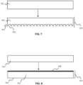
- an array of interconnected microchannels 506 is formed, e.g., drilled, into the plate throughout the surface of the plate to form the wick structure 505 of the evaporator 502, as shown in FIG. 7 .
- the dimensions of the micropillar/channels 506 can vary based on the heat load of the light engine of the LED system 310.
- the size of a channel 506 can vary from anything between 100 ⁇ m to 500 ⁇ m according to the filler ratio needed or used.
- the evaporator 502 is an15 implementation of the evaporator 304 illustrated in FIG. 3 .
- a condenser 504 of the thermal diode 501 is prepared.
- a heat conducting plate 503 is provided.
- the plate 503 can be, for example, a metal, preferably copper.
- any suitable heat conducting plate can be employed.
- the condenser height can vary from, for example, 5mm to 10mm in height.
- a hydrophobic layer 508 is deposited on the plate 503.
- the hydrophobic layer 508 can be, for example, graphene or a grafted polymer.
- the hydrophobic layer 508 can be a graphene monolayer.
- any suitable hydrophobic layer can be employed.
- the condenser 504 is an implementation of the condenser 302 illustrated in FIG. 3 .
- the evaporator 502 and the condenser 504 are conjoined.
- a gasket 512 is provided between the condenser 504 and the evaporator 502.
- the gasket 512 is an O-ring.
- the chamber 902 is at least partially filled with a fluid medium 910, and any non-condensable gases are removed.
- the medium 910 can be water
- the chamber 902 can be injected with water to fill the microchannel structure 506, where the gasket 512 is an16 insulating water-resistant gasket.
- any suitable liquid medium can be employed.
- the fluid medium 510 can be composed of liquid 910 and a gaseous form of the liquid 910.
- the medium 510 can be composed of both water and water vapor during operation of the lighting system 500 when heat is generated by the LEDs 312 of the LED system 310 and/or other components coupled to the thermal diode 501, such as, for example, the driver 316.
- the evaporator 502 and the condenser 504 can be compressed and the chamber 902 can be sealed, as illustrated in FIG. 10 .
- the evaporator and the condenser are compressed so that the condenser is spaced 1-500 ⁇ m from the evaporator.
- the condenser is spaced 200-400 ⁇ m from the evaporator, e.g. 250 ⁇ m.
- the LED system 310 is coupled to the droplet thermal diode 501, and at step 622, one or more electronic components can be coupled to the thermal diode 501 to form the lighting system 500 of FIG. 5 .
- the LED system 310 can be coupled to the evaporator 502 at step 620, while one or more electronic components can be coupled to the condenser 504 of thermal diode 501 at step 622.
- the driver 316 can be coupled to the condenser 504.
- any electronic component of the lighting system can be coupled to the condenser 504.
- the LED system 310 and the electronic component(s) are directly coupled, for example, by mechanical means, such as a screw or clip, to the evaporator 502 and condenser 504, respectively.
- the coupling here is direct, other couplings in which one or more heat conducting elements are disposed between the LED system 310 and the evaporator 502 and/or between the electronic component(s) and the condenser 504 can be employed.
- heat conductive glue can be used to couple the LED system 310 to the evaporator and/or to couple the electronic component(s) and the condenser 504.
- heat conductive wires or tracers can be used to couple the LED system 310 to the evaporator and/or to couple the electronic component(s) and the condenser 504.
- the diode 501 can be adapted to various heat loads by altering the filler ratio at step 614.
- the heat transfer capability of the diode 501 can be scaled to handle various heat loads input into the diode 501 by the LEDs 312 and/or by the electronic component(s), in this case a driver 316, on the opposing side of the diode 501.
- an empirical correlation can be determined for the specific application between liquid filler ratio and the heat load imposed by the heat sources 312 and/or 316.
- a liquid filler ratio can be empirically determined through repetition with various amounts of liquid filler and corresponding observation of the heat loads imposed by the heat sources 312 and/or 316 at each iteration. Accordingly, at step 614, the final amount of liquid medium 910 placed on the evaporator during filling can be tailored to the determined ratio, which in turn is empirically determined based on the heat load in the system 500 imposed by the heat sources 312 and/or 316.
- inventive embodiments are presented by way of example only and that, within the scope of the appended claims and equivalents thereto, inventive embodiments may be practiced otherwise than as specifically described and claimed.
- inventive embodiments of the present disclosure are directed to each individual feature, system, article, material, kit, and/or method described herein.
- a reference to "A and/or B", when used in conjunction with open-ended language such as “comprising” can refer, in one embodiment, to A only (optionally including elements other than B); in another embodiment, to B only (optionally including elements other than A); in yet another embodiment, to both A and B (optionally including other elements); etc.
- the phrase "at least one,” in reference to a list of one or more elements, should be understood to mean at least one element selected from any one or more of the elements in the list of elements, but not necessarily including at least one of each and every element specifically listed within the list of elements and not excluding any combinations of elements in the list of elements.
- This definition also allows that elements may optionally be present other than the elements specifically identified within the list of elements to which the phrase "at least one" refers, whether related or unrelated to those elements specifically identified.
- At least one of A and B can refer, in one embodiment, to at least one, optionally including more than one, A, with no B present (and optionally including elements other than B); in another embodiment, to at least one, optionally including more than one, B, with no A present (and optionally including elements other than A); in yet another embodiment, to at least one, optionally including more than one, A, and at least one, optionally including more than one, B (and optionally including other elements); etc.
Landscapes
- Engineering & Computer Science (AREA)
- General Engineering & Computer Science (AREA)
- Life Sciences & Earth Sciences (AREA)
- Sustainable Development (AREA)
- Physics & Mathematics (AREA)
- Thermal Sciences (AREA)
- Mechanical Engineering (AREA)
- Non-Portable Lighting Devices Or Systems Thereof (AREA)
Priority Applications (1)
| Application Number | Priority Date | Filing Date | Title |
|---|---|---|---|
| EP22198578.1A EP4345371A1 (fr) | 2022-09-29 | 2022-09-29 | Systèmes et procédés d'éclairage utilisant des diodes thermiques pour la gestion de la chaleur |
Applications Claiming Priority (1)
| Application Number | Priority Date | Filing Date | Title |
|---|---|---|---|
| EP22198578.1A EP4345371A1 (fr) | 2022-09-29 | 2022-09-29 | Systèmes et procédés d'éclairage utilisant des diodes thermiques pour la gestion de la chaleur |
Publications (1)
| Publication Number | Publication Date |
|---|---|
| EP4345371A1 true EP4345371A1 (fr) | 2024-04-03 |
Family
ID=84329847
Family Applications (1)
| Application Number | Title | Priority Date | Filing Date |
|---|---|---|---|
| EP22198578.1A Ceased EP4345371A1 (fr) | 2022-09-29 | 2022-09-29 | Systèmes et procédés d'éclairage utilisant des diodes thermiques pour la gestion de la chaleur |
Country Status (1)
| Country | Link |
|---|---|
| EP (1) | EP4345371A1 (fr) |
Citations (2)
| Publication number | Priority date | Publication date | Assignee | Title |
|---|---|---|---|---|
| KR101439954B1 (ko) * | 2014-04-24 | 2014-11-04 | (주)일광조명 | 엘이디 조명장치 |
| WO2021263114A2 (fr) * | 2020-06-25 | 2021-12-30 | Virginia Polytechnic Institute And State University | Diode thermique de type à gouttelette de pontage plane |
-
2022
- 2022-09-29 EP EP22198578.1A patent/EP4345371A1/fr not_active Ceased
Patent Citations (2)
| Publication number | Priority date | Publication date | Assignee | Title |
|---|---|---|---|---|
| KR101439954B1 (ko) * | 2014-04-24 | 2014-11-04 | (주)일광조명 | 엘이디 조명장치 |
| WO2021263114A2 (fr) * | 2020-06-25 | 2021-12-30 | Virginia Polytechnic Institute And State University | Diode thermique de type à gouttelette de pontage plane |
Non-Patent Citations (1)
| Title |
|---|
| EDALATPOUR MOJTABA ET AL: "Bridging-Droplet Thermal Diodes", ADVANCED FUNCTIONAL MATERIALS, vol. 30, no. 43, 18 August 2020 (2020-08-18), DE, pages 2004451, XP055903212, ISSN: 1616-301X, Retrieved from the Internet <URL:https://onlinelibrary.wiley.com/doi/full-xml/10.1002/adfm.202004451> DOI: 10.1002/adfm.202004451 * |
Similar Documents
| Publication | Publication Date | Title |
|---|---|---|
| US9488359B2 (en) | Passive phase change radiators for LED lamps and fixtures | |
| EP2718616B1 (fr) | Dispositif d'éclairage à semi-conducteur utilisant des caloducs dans un boîtier | |
| US8304970B2 (en) | Light unit with induced convection heat sink | |
| KR100998480B1 (ko) | 열전달/발산 모듈을 구비한 반도체 발광 장치 | |
| US8556448B2 (en) | Airfield lighting device | |
| KR102071341B1 (ko) | 색 조정가능 발광 조립체, 광원 및 조명 기구 | |
| US20110305025A1 (en) | Led-based lamps and thermal management systems therefor | |
| CN105179969A (zh) | Led灯泡及包含该led灯泡的灯具 | |
| US9163819B2 (en) | Light assembly with a heat dissipation layer | |
| TW201319460A (zh) | 對於遠距波長轉換具有改善熱傳導特性之波長轉換構件 | |
| WO2012067347A2 (fr) | Unité de refroidissement pour appareil d'éclairage à del, et appareil d'éclairage à del utilisant ladite unité de refroidissement | |
| TW201634869A (zh) | 具有塑膠殼體的戶外發光二極體(led)燈具 | |
| CN101281902B (zh) | 高功率发光二极管照明灯具与其散热模块 | |
| CN105706537B (zh) | 组件和制造组件的方法 | |
| CN101672460A (zh) | Led基板散热结构及包括该结构的led灯管 | |
| KR101270257B1 (ko) | 튜브형 엘이디 조명 램프용 히트 파이프 타입 히트싱크 및 이를 이용한 튜브형 엘이디 조명 램프 | |
| EP4345371A1 (fr) | Systèmes et procédés d'éclairage utilisant des diodes thermiques pour la gestion de la chaleur | |
| CN201589142U (zh) | 半导体光源工矿灯 | |
| CN101526202A (zh) | 发光二极管照明装置 | |
| TWI431737B (zh) | 發光二極體照明裝置及其水冷式散熱模組 | |
| Li et al. | Critical design issues of retrofit light-emitting diode (LED) light bulb | |
| KR101457601B1 (ko) | 조립방식의 엘이디 조명장치용 방열기구 | |
| KR101321581B1 (ko) | 발광 다이오드 조명 기기 | |
| CN113853499A (zh) | 包括基板和散热器结构的光源 | |
| CN205782085U (zh) | 一种led灯组件 |
Legal Events
| Date | Code | Title | Description |
|---|---|---|---|
| PUAI | Public reference made under article 153(3) epc to a published international application that has entered the european phase |
Free format text: ORIGINAL CODE: 0009012 |
|
| STAA | Information on the status of an ep patent application or granted ep patent |
Free format text: STATUS: THE APPLICATION HAS BEEN PUBLISHED |
|
| AK | Designated contracting states |
Kind code of ref document: A1 Designated state(s): AL AT BE BG CH CY CZ DE DK EE ES FI FR GB GR HR HU IE IS IT LI LT LU LV MC MK MT NL NO PL PT RO RS SE SI SK SM TR |
|
| STAA | Information on the status of an ep patent application or granted ep patent |
Free format text: STATUS: THE APPLICATION HAS BEEN REFUSED |
|
| 18R | Application refused |
Effective date: 20240627 |