EP4345491A1 - Capteur radar pour un véhicule et procédé d'intégration d'un capteur radar dans un véhicule - Google Patents
Capteur radar pour un véhicule et procédé d'intégration d'un capteur radar dans un véhicule Download PDFInfo
- Publication number
- EP4345491A1 EP4345491A1 EP22199026.0A EP22199026A EP4345491A1 EP 4345491 A1 EP4345491 A1 EP 4345491A1 EP 22199026 A EP22199026 A EP 22199026A EP 4345491 A1 EP4345491 A1 EP 4345491A1
- Authority
- EP
- European Patent Office
- Prior art keywords
- radar
- vehicle
- radar sensor
- interface unit
- waves
- Prior art date
- Legal status (The legal status is an assumption and is not a legal conclusion. Google has not performed a legal analysis and makes no representation as to the accuracy of the status listed.)
- Pending
Links
Images


Classifications
-
- G—PHYSICS
- G01—MEASURING; TESTING
- G01S—RADIO DIRECTION-FINDING; RADIO NAVIGATION; DETERMINING DISTANCE OR VELOCITY BY USE OF RADIO WAVES; LOCATING OR PRESENCE-DETECTING BY USE OF THE REFLECTION OR RERADIATION OF RADIO WAVES; ANALOGOUS ARRANGEMENTS USING OTHER WAVES
- G01S7/00—Details of systems according to groups G01S13/00, G01S15/00, G01S17/00
- G01S7/02—Details of systems according to groups G01S13/00, G01S15/00, G01S17/00 of systems according to group G01S13/00
- G01S7/03—Details of HF subsystems specially adapted therefor, e.g. common to transmitter and receiver
- G01S7/032—Constructional details for solid-state radar subsystems
-
- G—PHYSICS
- G01—MEASURING; TESTING
- G01S—RADIO DIRECTION-FINDING; RADIO NAVIGATION; DETERMINING DISTANCE OR VELOCITY BY USE OF RADIO WAVES; LOCATING OR PRESENCE-DETECTING BY USE OF THE REFLECTION OR RERADIATION OF RADIO WAVES; ANALOGOUS ARRANGEMENTS USING OTHER WAVES
- G01S13/00—Systems using the reflection or reradiation of radio waves, e.g. radar systems; Analogous systems using reflection or reradiation of waves whose nature or wavelength is irrelevant or unspecified
- G01S13/88—Radar or analogous systems specially adapted for specific applications
- G01S13/93—Radar or analogous systems specially adapted for specific applications for anti-collision purposes
- G01S13/931—Radar or analogous systems specially adapted for specific applications for anti-collision purposes of land vehicles
-
- G—PHYSICS
- G01—MEASURING; TESTING
- G01S—RADIO DIRECTION-FINDING; RADIO NAVIGATION; DETERMINING DISTANCE OR VELOCITY BY USE OF RADIO WAVES; LOCATING OR PRESENCE-DETECTING BY USE OF THE REFLECTION OR RERADIATION OF RADIO WAVES; ANALOGOUS ARRANGEMENTS USING OTHER WAVES
- G01S17/00—Systems using the reflection or reradiation of electromagnetic waves other than radio waves, e.g. lidar systems
- G01S17/88—Lidar systems specially adapted for specific applications
- G01S17/93—Lidar systems specially adapted for specific applications for anti-collision purposes
- G01S17/931—Lidar systems specially adapted for specific applications for anti-collision purposes of land vehicles
-
- G—PHYSICS
- G01—MEASURING; TESTING
- G01S—RADIO DIRECTION-FINDING; RADIO NAVIGATION; DETERMINING DISTANCE OR VELOCITY BY USE OF RADIO WAVES; LOCATING OR PRESENCE-DETECTING BY USE OF THE REFLECTION OR RERADIATION OF RADIO WAVES; ANALOGOUS ARRANGEMENTS USING OTHER WAVES
- G01S7/00—Details of systems according to groups G01S13/00, G01S15/00, G01S17/00
- G01S7/02—Details of systems according to groups G01S13/00, G01S15/00, G01S17/00 of systems according to group G01S13/00
- G01S7/027—Constructional details of housings, e.g. form, type, material or ruggedness
-
- G—PHYSICS
- G01—MEASURING; TESTING
- G01S—RADIO DIRECTION-FINDING; RADIO NAVIGATION; DETERMINING DISTANCE OR VELOCITY BY USE OF RADIO WAVES; LOCATING OR PRESENCE-DETECTING BY USE OF THE REFLECTION OR RERADIATION OF RADIO WAVES; ANALOGOUS ARRANGEMENTS USING OTHER WAVES
- G01S7/00—Details of systems according to groups G01S13/00, G01S15/00, G01S17/00
- G01S7/02—Details of systems according to groups G01S13/00, G01S15/00, G01S17/00 of systems according to group G01S13/00
- G01S7/03—Details of HF subsystems specially adapted therefor, e.g. common to transmitter and receiver
-
- G—PHYSICS
- G01—MEASURING; TESTING
- G01S—RADIO DIRECTION-FINDING; RADIO NAVIGATION; DETERMINING DISTANCE OR VELOCITY BY USE OF RADIO WAVES; LOCATING OR PRESENCE-DETECTING BY USE OF THE REFLECTION OR RERADIATION OF RADIO WAVES; ANALOGOUS ARRANGEMENTS USING OTHER WAVES
- G01S7/00—Details of systems according to groups G01S13/00, G01S15/00, G01S17/00
- G01S7/02—Details of systems according to groups G01S13/00, G01S15/00, G01S17/00 of systems according to group G01S13/00
- G01S7/40—Means for monitoring or calibrating
- G01S7/4004—Means for monitoring or calibrating of parts of a radar system
- G01S7/4026—Antenna boresight
-
- G—PHYSICS
- G01—MEASURING; TESTING
- G01S—RADIO DIRECTION-FINDING; RADIO NAVIGATION; DETERMINING DISTANCE OR VELOCITY BY USE OF RADIO WAVES; LOCATING OR PRESENCE-DETECTING BY USE OF THE REFLECTION OR RERADIATION OF RADIO WAVES; ANALOGOUS ARRANGEMENTS USING OTHER WAVES
- G01S7/00—Details of systems according to groups G01S13/00, G01S15/00, G01S17/00
- G01S7/48—Details of systems according to groups G01S13/00, G01S15/00, G01S17/00 of systems according to group G01S17/00
- G01S7/483—Details of pulse systems
- G01S7/486—Receivers
- G01S7/4861—Circuits for detection, sampling, integration or read-out
-
- H—ELECTRICITY
- H01—ELECTRIC ELEMENTS
- H01Q—ANTENNAS, i.e. RADIO AERIALS
- H01Q1/00—Details of, or arrangements associated with, antennas
- H01Q1/42—Housings not intimately mechanically associated with radiating elements, e.g. radome
- H01Q1/422—Housings not intimately mechanically associated with radiating elements, e.g. radome comprising two or more layers of dielectric material
-
- G—PHYSICS
- G01—MEASURING; TESTING
- G01S—RADIO DIRECTION-FINDING; RADIO NAVIGATION; DETERMINING DISTANCE OR VELOCITY BY USE OF RADIO WAVES; LOCATING OR PRESENCE-DETECTING BY USE OF THE REFLECTION OR RERADIATION OF RADIO WAVES; ANALOGOUS ARRANGEMENTS USING OTHER WAVES
- G01S13/00—Systems using the reflection or reradiation of radio waves, e.g. radar systems; Analogous systems using reflection or reradiation of waves whose nature or wavelength is irrelevant or unspecified
- G01S13/88—Radar or analogous systems specially adapted for specific applications
- G01S13/93—Radar or analogous systems specially adapted for specific applications for anti-collision purposes
- G01S13/931—Radar or analogous systems specially adapted for specific applications for anti-collision purposes of land vehicles
- G01S2013/9327—Sensor installation details
- G01S2013/93274—Sensor installation details on the side of the vehicles
-
- G—PHYSICS
- G01—MEASURING; TESTING
- G01S—RADIO DIRECTION-FINDING; RADIO NAVIGATION; DETERMINING DISTANCE OR VELOCITY BY USE OF RADIO WAVES; LOCATING OR PRESENCE-DETECTING BY USE OF THE REFLECTION OR RERADIATION OF RADIO WAVES; ANALOGOUS ARRANGEMENTS USING OTHER WAVES
- G01S13/00—Systems using the reflection or reradiation of radio waves, e.g. radar systems; Analogous systems using reflection or reradiation of waves whose nature or wavelength is irrelevant or unspecified
- G01S13/88—Radar or analogous systems specially adapted for specific applications
- G01S13/93—Radar or analogous systems specially adapted for specific applications for anti-collision purposes
- G01S13/931—Radar or analogous systems specially adapted for specific applications for anti-collision purposes of land vehicles
- G01S2013/9327—Sensor installation details
- G01S2013/93275—Sensor installation details in the bumper area
Definitions
- the present disclosure relates to a radar sensor for a vehicle and to a method for integrating a radar sensor in a vehicle.
- a radar sensor of such a system When integrating a radar system in a vehicle, a radar sensor of such a system is usually located behind plastic composite parts of the vehicle. Such plastic parts include a fascia of the vehicle, for example, if the radar sensor is to be located in a front part of the vehicle. As an alternative, a radar sensor may be implemented visibly in an opening or cutout of the vehicle body. For both cases, the number of positions is restricted at which the radar sensor can be installed in or at the vehicle.
- the impact of the fascia on the radar sensor may be evaluated by simulating transmitted and received radar waves in order to determine the best position for the radar sensor.
- the attenuation of the transmitted and received radar waves is high since the waves have usually to pass through a radome of the radar sensor and through the fascia. Therefore, a loss of 1 to 5 dB may occur, for example, such that the performance of the radar sensor is degraded significantly.
- the radar performance refers to the field of view and the maximum range available for the radar sensor and to the ability to perform angle finding.
- the radar sensor is implemented visibly in an opening or cutout of an outer surface of the vehicle, a degradation of the radar performance may be prevented.
- the number of positions for such an installation may be also strongly restricted due to further vehicle requirements.
- the body or outer shell of the vehicle mostly requires conformal structures which may also limit the number of installation positions being available for a radar sensor.
- the requirement of conformal structures may prevent providing an opening or cutout at desired installation positions of the radar sensor.
- the aesthetic appearance of the vehicle may be deteriorated by the opening or cutout being visible in the vehicle body.
- radar sensors are usually hidden behind plastic parts of the vehicle, which is accompanied by the attenuation problems as described before.
- the present disclosure provides a radar sensor, computer implemented method, a computer system and a non-transitory computer readable medium according to the independent claims. Embodiments are given in the subclaims, the description and the drawings.
- the present disclosure is directed at a radar sensor for a vehicle.
- the radar sensor comprises a radar transmit and receive unit configured to transmit radar waves to an external environment of the vehicle and to receive radar waves from the external environment of the vehicle, and an interface unit attached to the radar transmit and receive unit.
- One or more parameters of the interface unit e.g. design and/or material parameters, are adjusted to fit a predetermined installation position at the vehicle with respect to desired characteristics of the transmitted and received radar waves.
- the term "radar waves” generally refers to electromagnetic waves that are transmitted and received by the radar sensor.
- the radar transmit and receive unit may include a plurality of radar transmit elements for transmitting the radar waves and a plurality of radar receive elements for receiving radar waves which are reflected at objects in the external environment of the vehicle.
- the radar transmit and receive unit may further include suitable antennas for transmitting and receiving the radar waves in a range of wavelengths being suitable for automotive applications.
- the interface unit may be configured to perform an impedance matching for the radar transmit and receive unit, i.e. between radar transmit and receive antennas and an outer shell of the vehicle.
- the interface unit may be configured to perform a "pattern function" for the transmitted and received radar waves. That is, a shape, i.e. the geometry in three dimensions, and dielectric properties of the interface unit may be designed in such a manner that a desired pattern with respect to intensity and angle distribution of the transmitted and received radar waves may be achieved.
- the desired characteristics of the transmitted and received radar waves to which the interface unit is designed for may therefore include the impedance matching and the pattern function properties. Due to this, a field of view, a maximum range and a correction capability for proper angle finding may be achieved accordingly by the design of the interface unit.
- the design and/or material parameters of the interface unit may be adjusted to desired antenna radiation characteristics of the radar transmit and receive unit and to the angle finding performance over azimuth and elevation angles. Therefore, the performance of the radar sensor may be improved for the predetermined installation position at the vehicle due to the aforementioned properties of the interface unit.
- the interface unit Due to the design flexibility of the interface unit, additional positions are available for the integration of the radar sensor which are not available for the radar integration performed in the conventional manner, e.g. by placing the radar sensor behind a fascia, behind a bumper or visibly in an opening of a vehicle body.
- the radar sensor may be aesthetically integrated due to an adjustment of the interface unit regarding its shape, wherein an integration in metal and plastic vehicle parts may be feasible.
- conformal and smooth outer structures of the vehicle may be achieved in which the radar sensor may be optically invisible from outside the vehicle.
- the radar sensor may be easily replaced in case of a malfunction.
- the interface unit may replace a radome of the radar sensor and a portion of the fascia at the predetermined installation position.
- the interface unit may act as a radome and a fascia. Since the interface unit is attached to the radar transmit and receive unit, the usual distance between the radar sensor and the fascia is eliminated. Therefore, multiple reflections of the radar waves, e.g. at the fascia, may be avoided or at least strongly reduced.
- the radar sensor may be integrated more flexibly in the vehicle while the performance of the radar sensor is improved at the same time.
- the one or more design and/or material parameters of the interface unit may be configured to provide a desired radiation pattern for the transmitted and received radar waves. That is, the shape and the dielectric properties of the interface unit may be designed such that the desired radiation pattern is achieved for the transmitted and received radar waves.
- the radiation pattern may also be denoted as antenna radiation pattern since it is mostly provided by antennas of the radar transmit and receive unit.
- the interface unit may provide a further possibility for arranging the radiation pattern of the radar waves, i.e. in addition to an internal configuration of the radar transmit and receive unit, e.g. by an orientation and an alignment of the antennas.
- the desired radiation pattern may include a coincidence of phase patterns associated with at least two elements of the radar transmit and receive unit. That is, according to the desired radiation pattern it may be requested to design the interface unit in such a manner that the coincidence of the phase patterns may be achieved for at least two elements of the radar transmit and receive unit, e.g. for corresponding antennas. By this means, the angle finding performance of the radar sensor may remain or may be improved.
- the interface unit may include at least one layer, and a thickness and/or dielectric properties of each of the at least one layer may be adjusted to provide the desired radiation pattern for the transmitted and received radar waves.
- the thickness and the dielectric properties may therefore be the design and material parameters which are adjusted or tuned to the predetermined installation position at the vehicle with respect to desired characteristics of the transmitted and received radar waves.
- the dielectric properties which may be adjusted are the dielectric permittivity ⁇ r or the dielectric loss tan ⁇ of the at least one layer, or both.
- the interface unit may further include at least two layers, and each of these layers may have different dielectric properties, i.e. different from the dielectric properties of the other layers.
- the at least two layers may also include an interface layer which may be located between two other layers, and a shape, i.e. the geometrical design, and/or dielectric properties of the interface layer may be configured such that the desired radiation pattern for the transmitted and received radar waves may be provided.
- the shape or geometrical design of the interface layer may include at least one protrusion or at least one recess extending from or into one of the other two layers. Although three layers are considered in this embodiment, a greater number of layers may be provided including a respective interface layer between two other layers.
- the interface unit may include at least one cavity in order to provide the desired radiation pattern for the transmitted and received radar waves.
- the cavity may be filled with air or another material having other dielectric properties as the rest of the interface unit.
- a three-dimensional geometry, i.e. the spatial form or shape, of the interface unit may be adjusted to the desired installation position at the vehicle with respect to desired characteristics of the transmitted and received radar waves. This may be performed even in conformal outer shapes of the vehicle.
- an outer surface of the interface unit may be adjusted to an outer surface of the vehicle, e.g. of the vehicle body. For example, metal and/or plastic parts of the vehicle may be flush with the outer surface of the interface unit. Due to this spatial adjustment, the radar sensor may be optically invisible from outside the vehicle. Hence, the desired aesthetic appearance of the outer surface of the vehicle is ensured by such a spatial adjustment of the interface unit.
- the radar transmit and receive unit may include a printed circuit board including a plurality of molded antennas for transmitting and receiving radar waves, and the interface unit may be located adjacent to the printed circuit board.
- the molded antennas may be broadband antennas.
- the interface unit may be directly connected to the radar transmit and receive unit such that no gap or only a small gap is provided between the interface unit and the radar transmit and receive unit. Due to the small distance between the interface unit and the molded antennas, multiple reflections of the transmitted radar waves may be suppressed.
- the radar transmit and receive unit may further include a chip or device for providing the transmission signals and the receive signals of the radar sensor, and a further board configured as a holder for the chip or device and the printed circuit board and to include further electric and electronic elements for operating the radar sensor.
- the radar transmit and receive unit may have a modular structure which facilitates maintenance and repair of the radar sensor.
- the present disclosure is directed at a vehicle comprising at least one radar sensor as described above.
- a vehicle comprising at least one radar sensor as described above.
- the at least one radar sensor may be located in an opening at an outer surface of the vehicle. Hence, the outer surface of the interface unit may be adjusted to this outer surface of the vehicle in the area of the opening.
- the interface unit of the radar sensor may therefore replace a part of the fascia of the vehicle such that the radar sensor may be optically invisible when the vehicle is viewed from the outside.
- the at least one radar sensor may be located behind a bumper of the vehicle.
- the interface unit of the radar sensor may also be an interface between the bumper and molded antennas which may be provided within a printed circuit board of the radar transmit and receive unit.
- the shape of the interface unit e.g. its surface facing away from the radar transmit and receive unit, may be adapted to an inner surface of the bumper such that the interface unit is fully covered by the bumper.
- the vehicle may comprise at least one coating layer and at least one painting layer covering the interface unit.
- a primer layer may be provided on top of the interface unit, a paint layer may be applied on the primer layer, and a clear coat layer may be applied on the painting layer.
- the interface unit may be further adjusted to the respective spatial and dielectric characteristics of the at least one coating layer and of the at least one painting layer at the predetermined position of the radar sensor.
- the spatial and dielectric characteristics may include the respective thickness and the dielectric permittivity ⁇ r of each layer.
- a respective tolerance may be predefined in the design phase of the vehicle, and the interface unit may be designed and adjusted such that the desired characteristic of the transmitted and received radar waves are still achieved for the predefined tolerances defined with respect to the at least one coating layer and the at least one painting layer.
- the coating and painting layers may not only be provided for achieving a smooth and aesthetic appearance of the outer surface of the vehicle, but also for achieving the required dielectric properties in connection with the interface unit.
- the present disclosure is directed at a computer implemented method for integrating a radar sensor in a vehicle.
- the radar sensor includes a radar transmit and receive unit configured to transmit radar waves to an external environment of the vehicle and to receive radar waves from the external environment of the vehicle, and an interface unit being attached to the radar transmit and receive unit.
- a desired installation position of the radar sensor at the vehicle is determined, and one or more design and/or material parameters of the interface unit are adjusted to fit the desired installation position with respect to desired characteristics of the transmitted and received radar waves.
- the method performs the adjustment of the interface unit of the radar sensor to the installation position which is determined in a preceding method step. Therefore, the benefits, the advantages and the disclosure of the radar sensor and the vehicle as described above are also valid for the computer implemented method.
- Determining the desired installation position of the radar sensor may include the steps of receiving data associated with a geometrical shape of the vehicle, simulating the transmitted radar waves for a plurality of candidate positions at the vehicle based on the received data, and selecting one of the candidate positions as the desired installation position for which a deviation between a radiation pattern of the simulated transmitted radar waves and a desired radiation pattern is minimized. In other words, an optimization process is performed to find the best position for the radar sensor at the vehicle.
- the data associated with the geometrical shape of the vehicle may include CAD data of the vehicle which are generated during a design phase of the vehicle.
- the present disclosure is directed at a computer system, said computer system being configured to carry out several or all steps of the computer implemented method described herein.
- the computer system may comprise a processing unit, at least one memory unit and at least one non-transitory data storage.
- the non-transitory data storage and/or the memory unit may comprise a computer program for instructing the computer to perform several or all steps or aspects of the computer implemented method described herein.
- the present disclosure is directed at a non-transitory computer readable medium comprising instructions for carrying out several or all steps or aspects of the computer implemented method described herein.
- the computer readable medium may be configured as: an optical medium, such as a compact disc (CD) or a digital versatile disk (DVD); a magnetic medium, such as a hard disk drive (HDD); a solid-state drive (SSD); a read only memory (ROM), such as a flash memory; or the like.
- the computer readable medium may be configured as a data storage that is accessible via a data connection, such as an internet connection.
- the computer readable medium may, for example, be an online data repository or a cloud storage.
- the present disclosure is also directed at a computer program for instructing a computer to perform several or all steps or aspects of the computer implemented method described herein.
- Fig. 1 depicts a radar sensor 100 which is integrated in a vehicle.
- the radar sensor 100 includes a radar transmit and receive unit 110 and an interface unit 120 which is attached to the radar transmit and receive unit 110.
- the radar sensor 100 further includes a housing 130.
- the radar transmit and receive unit 110 includes a printed circuit board 111 which is provided with molded antennas in order to transmit radar waves through the interface unit 120 to an exterior environment of the vehicle and to receive radar waves from the external environment.
- the fixtures 141 extend through the printed circuit board 111, for example, for mounting the radar sensor at the portion 140 of the vehicle body.
- the radar transmit and receive unit 110 further includes a monolithic microwave integrated circuit (MMIC) 112 which generates transmit signals TX1, TX2, TX3 for transmitting radar waves via the molded antennas of the printed circuit board 111, and receive signals RX1, RX2, RX3, RX 4 from receiving radar waves which are detected by further molded antennas of the printed circuit board 111.
- MMIC monolithic microwave integrated circuit
- each pair of a transmit signal TX and a receive signal RX constitutes a radar channel such that a multiple-input multiple-output (MIMO) radar system having twelve channels is generated.
- MIMO multiple-input multiple-output
- the radar transmit and receive unit 110 includes a multilayer 113 which is configured to be a holder for the MMIC 112 and the printed circuit board 111, and to provide further electrical and electronic functions for operating the radar sensor 100.
- the interface unit 120 is positioned in a cutout or opening defined by the portions 140 of the vehicle body (see also the opening 143 in Fig. 3B ). As such, the interface unit 120 is adjusted regarding its shape or spatial form to a desired or specific position at the vehicle body at which the radar sensor 100 is to be integrated.
- the portions 140 of the vehicle body and the interface unit 120 are depicted as parts having a plane outer surface and without any internal structures, the portions 140 of the vehicle body and the interface unit 120 may include a curvature such that the curvature of the interface unit 120 is adjusted to a corresponding curvature of the portions 140 of the vehicle body. By this means, a smooth and conformal outer appearance of the vehicle body will occur.
- the portion 140 of the vehicle body and an outer surface of the interface unit 120 are covered by coating and painting layers 150 which include an outer transparent or clear coat layer 151, a paint layer 152 and a primer layer 153.
- coating and painting layers 150 include an outer transparent or clear coat layer 151, a paint layer 152 and a primer layer 153.
- the interface unit 120 replaces a radome and a part of the fascia which are usually provided with radar sensors integrated in a vehicle. Due to this, the radar sensor 100 is located close to the outer surface of the vehicle. In other words, the distance between the printed circuit board 111 including the molded antennas and the exterior of the vehicle is reduced due to the interface unit 120 in comparison to the conventional installation of radar systems within a vehicle. Therefore, multiple reflections of transmitted radar waves are suppressed.
- the interface unit 120 is further adjusted to desired characteristics of the transmitted and received radar waves.
- impedance matching is performed by the interface unit 120, i.e. by its dielectric properties.
- an internal structure of the interface unit may be used in order to design the radiation pattern of the radar waves transmitted by the radar sensor 100.
- an interface unit 120 is depicted which includes a single dielectric structure.
- the interface unit 120 is shown in Fig. 2A as having a rectangular form, the shape of this interface unit 120 having the single dielectric structure can be adjusted to a predetermined installation position at the vehicle such that a certain impedance and pattern characteristic is achieved, e.g. by selecting a suitable thickness of the interface unit 120.
- the interface unit 120 as shown in Fig. 2B has a multilayer structure including, in this specific example, three different layers 121, 122, 123.
- the layers 121, 122, 123 each have a different respective dielectric permittivity ⁇ r1 , ⁇ r2 and ⁇ r3 , respectively.
- the second layer 122 is arranged between the first layer 121 and the third layer. Therefore, the second layer 122 is also denoted as an interface layer 122.
- a boundary or transition 124 between the first layer 121 and the interface layer 122 is designed such that features, in this case protrusions 125, are part of the interface layer 122 and extend into the first layer 121.
- the protrusions 125 have different length or extensions, e.g. L1 and L2, along the interface layer 122.
- the design of the transition 124 between the first layer 121 and second layer 122 e.g. regarding the geometrical shape and the change of dielectric permittivity, and the design of a similar transition between the second layer 122 and the third layer 123 are made such that the radar waves are matched between the first layer 121 and the second layer 122 as well as between the second layer 122 and third layer 123.
- the pattern of the transmitted and received radar waves is matched and modified by the configuration of the layers 121, 122, 123, in other words throughout the interface unit 120, e.g. regarding thickness and dielectric permittivity, and by the shape of the interface layer 122 between the first and third layers 121, 123.
- the pattern of the transmitted radar waves can be adjusted to a desired radiation pattern for the specific installation position of the radar sensor 100.
- three layers 121, 122, 123 are provided in this specific example as shown in Fig. 2B , a greater number of layers may be provided including a respective interface layer 122 between respective pairs of layers.
- Fig. 2C depicts an interface unit 120 comprising an outer layer 126 which surrounds a cavity 127 which is filled with air for the present example.
- the pattern characteristic of the transmitted and received radar waves can also be designed in a suitable manner.
- the spatial distribution of the dielectric permittivity may be designed in such a manner that an impedance matching is performed and desired patterns of the transmitted and received radar waves is achieved.
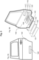
- Fig. 3 depicts an example for integrating the radar sensor 100 as shown in Fig. 1 in a vehicle door 142.
- Fig. 3A shows a plan view of the vehicle door 142 which includes the interface unit 120 at a position within a lower part of the vehicle door 142.
- Fig. 3B depicts an exploded view of the radar sensor 100 and of the coating and painting layers 151, 152, 153 at the vehicle door 142.
- the interface unit 120 is positioned in an opening 143 of the vehicle door 142 and attached to the radar transmit and receive unit 110 including the printed circuit board 111, the monolithic microwave integrated circuit (MMIC) 112 and the multilayer 113.
- the primer layer 153, the paint layer 152 and the transparent clear coat layer 151 are applied. Therefore, the radar sensor 100 is invisible from the outer side of the vehicle. Nevertheless, the interface unit 120 is shown at a specific position in Fig. 3A in order to illustrate a predetermined or desired installation position for the radar sensor 100 in form of the opening 143.
- the radar sensor 100 is not installed behind plastic components of the vehicle in the example as shown in Fig. 3 , but it is integrated in a metallic part of the vehicle door 142. Hence, the flexibility for integrating the radar sensor 100 at desired positions within the vehicle is improved by configuring the interface unit 120 in a suitable manner.
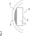
- Fig. 4 depicts another example for integrating the radar sensor 100 as shown in Fig. 1 in a vehicle.
- the radar sensor 100 is located behind a bumper 144 of the vehicle.
- the radar sensor 100 includes the radar transmit and receive unit 110 which is installed within the housing 130, and the interface unit 120 which is located between the radar transmit and receive unit 110 and the bumper 144.
- the interface unit 120 is also an interface between the bumper 144 and the molded antennas which are provided within the printed circuit board 111 (see Fig. 1 ).
- the shape of the interface unit 120 i.e. its outer surface facing away from the radar transmit and receive unit 110, is adapted to an inner surface of the bumper 144 such that the interface unit 120 is fully covered by the bumper 144.
- interface unit 120 For installing the radar sensor 100 behind the bumper 144 as shown Fig. 4 , fastening elements similar to the fixtures 141 (see Fig. 1 ) and/or adhesive layers are required.
- the internal properties of interface unit 120 as shown Fig. 4 e.g. the dielectric properties of one or more layers of the interface unit 120, are also designed to achieve the desired characteristics of the transmitted and received radar waves like a desired radiation pattern, i.e. in a similar manner as described above in context of Fig. 2 .
- the impact of the interface unit 120 on the transmitted and received radar waves can be simulated and corrected, if required, by a suitable software algorithm.
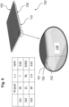
- Fig. 5 depicts a further embodiment of the radar sensor 100 which includes the radar transmit and receive unit 110 as shown in Fig. 1 , and a radome 128 which is located on top of the radar transmit and receive unit 110. That is, the radome 128 constitutes the interface unit 120 being attached to the radar transmit and receive unit 110.
- a conventional radome 128 may be modified in order to provide the properties of the interface unit 120 as described above.
- the radome 128 is covered by the coating and painting layers 150. As depicted in the enlarged section in the lower part of Fig. 4 , the primer layer 153, the paint layer 152 and the clear coat layer 151 are applied on top of the radome 128.
- the table of Fig. 4 provides a specific example for the thickness th in ⁇ m, the dielectric permittivity ⁇ r and the loss factor tan ⁇ for each of the three layers 151, 152, 153.
- the properties of the layers 151, 152, 153 may be defined as shown in the table of Fig. 4 , for example, and the internal structure of the radome 128 and/or the interface unit 120 as shown in Fig. 2 are provided thereafter in order to achieve desired characteristics of the transmitted and received radar waves of the radar sensor 100.
- the properties of the layers 151, 152, 153 as shown in the table of Fig. 4 may be associated with specific tolerances which are related to the specific installation position at the vehicle. Therefore, the interface unit 120 has to be designed, e.g. regarding its internal structure, such that the desired characteristics of the transmitted and received radar waves can be achieved with respect to the predefined tolerances.
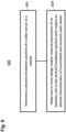
- Fig. 6 shows a flow diagram 600 illustrating a method for integrating a radar sensor in a vehicle according to various embodiments, wherein the radar sensor may include a radar transmit and receive unit configured to transmit radar waves to an external environment of the vehicle and to receive radar waves from the external environment of the vehicle, and an interface unit being attached to the radar transmit and receive unit.
- a desired installation position of the radar sensor is determined at the vehicle.
- one or more design and/or material parameters of the interface unit is adjusted to fit the desired installation position with respect to desired characteristics of the transmitted and received radar waves.
- determining the desired installation position of the radar sensor may include receiving data associated with a geometrical shape of the vehicle, simulating the transmitted radar waves for a plurality of candidate positions at the vehicle based on the received data, and selecting one of the candidate positions as the desired installation position for which a deviation between a radiation pattern of the simulated transmitted radar waves and a desired radiation pattern is minimized.
- a radar sensor for a vehicle may comprise a radar transmit and receive unit configured to transmit radar waves to an external environment of the vehicle and to receive radar waves from the external environment of the vehicle, and an interface unit attached to the radar transmit and receive unit, wherein one or more design and/or material parameters of the interface unit may be adjusted to fit a predetermined installation position at the vehicle with respect to desired characteristics of the transmitted and received radar waves.
- the design and/or material parameters of the interface unit may be configured to provide a desired radiation pattern for the transmitted and received radar waves.
- the desired radiation pattern may include a coincidence of phase patterns associated with at least two elements of the radar transmit and receive unit.
- the interface unit may include at least one layer, and a thickness and/or dielectric properties of each of the at least one layer may be adjusted to provide the desired radiation pattern for the transmitted and received radar waves.
- the interface unit may include at least two layers, each of the layers having different dielectric properties.
- the at least two layers may include an interface layer which may be located between two other layers, and a shape and/or dielectric properties of the interface layer may be configured to provide the desired radiation pattern for the transmitted and received radar waves.
- the interface unit may include at least one cavity in order to provide the desired radiation pattern for the transmitted and received radar waves.
- a shape of the interface unit may be adjusted to the desired installation position at the vehicle with respect to desired characteristics of the transmitted and received radar waves.
- the radar transmit and receive unit may include a printed circuit board including a plurality of molded antennas for transmitting and receiving radar waves, and the interface unit may be located adjacent to the printed circuit board.
- a vehicle may comprise at least one radar sensor as described above.
- the at least one radar sensor may be located in an opening at an outer surface of the vehicle.
- the at least one radar sensor may be located behind a bumper of the vehicle.
- the vehicle may comprise at least one coating layer and at least one painting layer covering the interface unit, and the interface unit may be further adjusted to respective spatial and dielectric characteristics of the at least one coating layer and of the at least one painting layer at the predetermined position of the radar sensor.
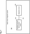
- Fig. 7 shows a radar sensor integration system 700 according to various embodiments.
- the radar sensor integration system 700 may include an installation position determination circuit 702 and an adjustment circuit 704.
- the installation position determination circuit 702 may be configured to determine a desired installation position of the radar sensor at the vehicle.
- the adjustment circuit 704 may be configured to adjust the interface unit to fit the desired installation position with respect to desired characteristics of the transmitted and received radar waves.
- the installation position determination circuit 702 and the adjustment circuit 704 may be coupled to each other, e.g. via an electrical connection 705, such as e.g. a cable or a computer bus or via any other suitable electrical connection to exchange electrical signals.
- an electrical connection 705 such as e.g. a cable or a computer bus or via any other suitable electrical connection to exchange electrical signals.
- a “circuit” may be understood as any kind of a logic implementing entity, which may be special purpose circuitry or a processor executing a program stored in a memory, firmware, or any combination thereof.
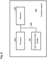
- Fig. 8 shows a computer system 800 with a plurality of computer hardware components configured to carry out steps of a computer implemented method for integrating a radar sensor in a vehicle according to various embodiments.
- the computer system 800 may include a processor 802, a memory 804, and a non-transitory data storage 806.
- the processor 802 may carry out instructions provided in the memory 804.
- the non-transitory data storage 806 may store a computer program, including the instructions that may be transferred to the memory 804 and then executed by the processor 802.
- the processor 802, the memory 804, and the non-transitory data storage 806 may be coupled with each other, e.g. via an electrical connection 808, such as e.g. a cable or a computer bus or via any other suitable electrical connection to exchange electrical signals.
- an electrical connection 808 such as e.g. a cable or a computer bus or via any other suitable electrical connection to exchange electrical signals.
- the processor 802, the memory 804 and the non-transitory data storage 806 may represent the installation position determination circuit 702 and the adjustment circuit 704 as described above.
- Coupled or “connection” are intended to include a direct “coupling” (for example via a physical link) or direct “connection” as well as an indirect “coupling” or indirect “connection” (for example via a logical link), respectively.
Landscapes
- Engineering & Computer Science (AREA)
- Radar, Positioning & Navigation (AREA)
- Remote Sensing (AREA)
- Physics & Mathematics (AREA)
- Computer Networks & Wireless Communication (AREA)
- General Physics & Mathematics (AREA)
- Electromagnetism (AREA)
- Radar Systems Or Details Thereof (AREA)
Priority Applications (3)
| Application Number | Priority Date | Filing Date | Title |
|---|---|---|---|
| EP22199026.0A EP4345491A1 (fr) | 2022-09-30 | 2022-09-30 | Capteur radar pour un véhicule et procédé d'intégration d'un capteur radar dans un véhicule |
| CN202311258413.5A CN117930280A (zh) | 2022-09-30 | 2023-09-27 | 用于车辆的雷达传感器和在车辆中集成雷达传感器的方法 |
| US18/374,861 US12591036B2 (en) | 2022-09-30 | 2023-09-29 | Radar sensor for a vehicle and method for integrating a radar sensor in a vehicle |
Applications Claiming Priority (1)
| Application Number | Priority Date | Filing Date | Title |
|---|---|---|---|
| EP22199026.0A EP4345491A1 (fr) | 2022-09-30 | 2022-09-30 | Capteur radar pour un véhicule et procédé d'intégration d'un capteur radar dans un véhicule |
Publications (1)
| Publication Number | Publication Date |
|---|---|
| EP4345491A1 true EP4345491A1 (fr) | 2024-04-03 |
Family
ID=83508979
Family Applications (1)
| Application Number | Title | Priority Date | Filing Date |
|---|---|---|---|
| EP22199026.0A Pending EP4345491A1 (fr) | 2022-09-30 | 2022-09-30 | Capteur radar pour un véhicule et procédé d'intégration d'un capteur radar dans un véhicule |
Country Status (3)
| Country | Link |
|---|---|
| US (1) | US12591036B2 (fr) |
| EP (1) | EP4345491A1 (fr) |
| CN (1) | CN117930280A (fr) |
Citations (2)
| Publication number | Priority date | Publication date | Assignee | Title |
|---|---|---|---|---|
| EP3758143A1 (fr) * | 2019-06-28 | 2020-12-30 | Aptiv Technologies Limited | Procédé de simulation d'une antenne |
| US20220013885A1 (en) * | 2021-09-23 | 2022-01-13 | Tae Young Yang | Radar antenna for vehicle bumper fascia |
Family Cites Families (40)
| Publication number | Priority date | Publication date | Assignee | Title |
|---|---|---|---|---|
| DE10207437A1 (de) * | 2002-02-22 | 2003-09-11 | Bosch Gmbh Robert | Radarsensor für Kraftfahrzeuge |
| JP4881984B2 (ja) * | 2009-08-28 | 2012-02-22 | 株式会社ファルテック | レドームの製造方法 |
| JP5494567B2 (ja) * | 2011-05-17 | 2014-05-14 | 株式会社デンソー | レーダ装置、検査システム、及び検査方法 |
| US9349234B2 (en) * | 2012-03-14 | 2016-05-24 | Autoconnect Holdings Llc | Vehicle to vehicle social and business communications |
| US20140091969A1 (en) * | 2012-10-02 | 2014-04-03 | Delphi Technologies, Inc. | Radome for a radar sensor assembly |
| DE102013221055A1 (de) * | 2013-10-17 | 2015-04-23 | Robert Bosch Gmbh | Kombination aus Radarsensor und Verkleidungsteil für ein Kraftfahrzeug |
| US9653796B2 (en) * | 2013-12-16 | 2017-05-16 | Valeo Radar Systems, Inc. | Structure and technique for antenna decoupling in a vehicle mounted sensor |
| DE102014211446A1 (de) * | 2014-06-16 | 2015-12-17 | Robert Bosch Gmbh | Haltevorrichtung für Nahbereichsradarsensoren |
| CN106662638B (zh) * | 2014-08-15 | 2019-06-25 | 罗伯特·博世有限公司 | 汽车雷达对准 |
| JP6363528B2 (ja) * | 2015-02-09 | 2018-07-25 | 株式会社デンソー | レーダ装置搭載構造 |
| US10328853B2 (en) * | 2017-01-16 | 2019-06-25 | Nio Usa, Inc. | Method and system for providing an escape route from a vehicle |
| US10399445B2 (en) * | 2017-01-16 | 2019-09-03 | Nio Usa, Inc. | Method and system for ejecting a charging handle from a vehicle |
| US10471829B2 (en) * | 2017-01-16 | 2019-11-12 | Nio Usa, Inc. | Self-destruct zone and autonomous vehicle navigation |
| US11151447B1 (en) * | 2017-03-13 | 2021-10-19 | Zoox, Inc. | Network training process for hardware definition |
| KR102335353B1 (ko) * | 2017-08-17 | 2021-12-03 | 현대자동차 주식회사 | 차량 레이더 검사 시스템 및 그 방법 |
| DE102018200396A1 (de) * | 2018-01-11 | 2019-07-11 | Robert Bosch Gmbh | Radarsystem mit mindestens einer verschlüsselbaren Datenleitung |
| DE102018200391A1 (de) * | 2018-01-11 | 2019-07-11 | Robert Bosch Gmbh | Radarsystem mit einer zentral angeordneten Analyseeinheit |
| DE102018200395A1 (de) * | 2018-01-11 | 2019-07-11 | Robert Bosch Gmbh | Radarsystem mit in einer zentralen Steuereinheit integriertem Taktgeber |
| DE102018200394A1 (de) * | 2018-01-11 | 2019-07-11 | Robert Bosch Gmbh | Radarsystem mit in einem Radarsensorkopf integrierter Analyseeinheit |
| DE102018202299A1 (de) * | 2018-02-15 | 2019-08-22 | Robert Bosch Gmbh | Antennenanordnung für einen Radarsensor |
| DE102018203941A1 (de) * | 2018-03-15 | 2019-09-19 | Robert Bosch Gmbh | Automatisches Kalibrieren eines Fahrzeug-Radarsensors |
| WO2019182974A2 (fr) * | 2018-03-21 | 2019-09-26 | Nvidia Corporation | Estimation de profondeur stéréo à l'aide de réseaux neuronaux profonds |
| JP7008216B2 (ja) * | 2018-03-28 | 2022-01-25 | パナソニックIpマネジメント株式会社 | レーダ装置 |
| DE102018207716A1 (de) * | 2018-05-17 | 2019-11-21 | Robert Bosch Gmbh | Radarsensorsystem und Verfahren zum Herstellen eines Radarsensorsystems |
| KR102487201B1 (ko) * | 2018-08-24 | 2023-01-10 | 현대자동차 주식회사 | 레이더 센서 각도 에이밍 시스템 및 그 방법 |
| EP3862785A4 (fr) * | 2018-10-05 | 2022-07-06 | Kyocera Corporation | Dispositif électronique, procédé de commande de dispositif électronique et programme de commande de dispositif électronique |
| KR102660413B1 (ko) * | 2018-10-08 | 2024-04-24 | 주식회사 에이치엘클레무브 | 레이더 장치 및 이를 포함하는 레이더 센싱 장치 |
| DE102020001515A1 (de) * | 2019-03-12 | 2020-09-17 | Semiconductor Components Industries, Llc | Hochauflösendes mimo-radar-system |
| US11340354B2 (en) * | 2019-06-26 | 2022-05-24 | Nio Usa, Inc. | Methods to improve location/localization accuracy in autonomous machines with GNSS, LIDAR, RADAR, camera, and visual sensors |
| JP7131506B2 (ja) | 2019-08-13 | 2022-09-06 | 豊田合成株式会社 | 車載センサカバー |
| WO2021070762A1 (fr) * | 2019-10-10 | 2021-04-15 | 京セラ株式会社 | Appareil électronique, procédé de commande et programme de commande d'appareil électronique |
| KR102599558B1 (ko) * | 2019-10-24 | 2023-11-08 | 현대모비스 주식회사 | 자동차용 센서 통합 모듈 |
| US11378681B2 (en) * | 2019-10-30 | 2022-07-05 | Nxp Usa, Inc. | Systems and methods for automotive synthetic aperture radar |
| KR102139172B1 (ko) * | 2020-01-06 | 2020-07-29 | 주식회사 모라이 | 가상환경에서의 자율주행차량 시뮬레이션 방법 |
| CN111324945B (zh) * | 2020-01-20 | 2023-09-26 | 阿波罗智能技术(北京)有限公司 | 传感器方案确定方法、装置、设备及存储介质 |
| US11113584B2 (en) * | 2020-02-04 | 2021-09-07 | Nio Usa, Inc. | Single frame 4D detection using deep fusion of camera image, imaging RADAR and LiDAR point cloud |
| FR3111195A1 (fr) * | 2020-06-09 | 2021-12-10 | Valeo Vision | Système de détection radar d’un véhicule |
| FR3116908B1 (fr) * | 2020-12-01 | 2022-12-09 | Valeo Vision | Ensemble de véhicule comprenant un capteur radar et un module lumineux de signalisation |
| FR3127817B1 (fr) * | 2021-10-01 | 2025-02-14 | Valeo Vision | Ensemble de véhicule comprenant un capteur radar et un agencement de couches |
| US12326497B2 (en) * | 2021-11-24 | 2025-06-10 | Sony Group Corporation | Circuitry and method |
-
2022
- 2022-09-30 EP EP22199026.0A patent/EP4345491A1/fr active Pending
-
2023
- 2023-09-27 CN CN202311258413.5A patent/CN117930280A/zh active Pending
- 2023-09-29 US US18/374,861 patent/US12591036B2/en active Active
Patent Citations (2)
| Publication number | Priority date | Publication date | Assignee | Title |
|---|---|---|---|---|
| EP3758143A1 (fr) * | 2019-06-28 | 2020-12-30 | Aptiv Technologies Limited | Procédé de simulation d'une antenne |
| US20220013885A1 (en) * | 2021-09-23 | 2022-01-13 | Tae Young Yang | Radar antenna for vehicle bumper fascia |
Also Published As
| Publication number | Publication date |
|---|---|
| US20240111018A1 (en) | 2024-04-04 |
| CN117930280A (zh) | 2024-04-26 |
| US12591036B2 (en) | 2026-03-31 |
Similar Documents
| Publication | Publication Date | Title |
|---|---|---|
| US9653796B2 (en) | Structure and technique for antenna decoupling in a vehicle mounted sensor | |
| US20190165484A1 (en) | Radar device | |
| JP6938210B2 (ja) | 低コストで軽量な機上気象レーダ用の集積アンテナ | |
| US20190165483A1 (en) | Radar device | |
| US20230101080A1 (en) | Electronic device including antenna | |
| US20140313069A1 (en) | Compound Circuit Board and Radar Device | |
| US12009577B2 (en) | Electronic device including an antenna | |
| CN109839629A (zh) | 雷达装置 | |
| CN112751186A (zh) | 用于机动车的雷达传感器的雷达天线罩和机动车 | |
| EP4345491A1 (fr) | Capteur radar pour un véhicule et procédé d'intégration d'un capteur radar dans un véhicule | |
| JP7244243B2 (ja) | アンテナ装置 | |
| CN110880639B (zh) | 天线装置和雷达装置 | |
| JP2010091301A (ja) | レーダ装置 | |
| WO2020200476A1 (fr) | Système d'antenne multibande et procédé pour fournir un tel système | |
| US20230341512A1 (en) | Mounting bracket for a radar sensor | |
| EP4449554A1 (fr) | Agencement de dispositif radar pour un véhicule et procédé pour produire un agencement de dispositif radar pour un véhicule | |
| JP7122649B2 (ja) | レーダ装置 | |
| US20190386395A1 (en) | Antenna device and radio device | |
| Garcia-Tejero et al. | Integrated waveguide-in-radome antenna for V-band in-cabin automotive radar applications | |
| TWI886732B (zh) | 超廣角雷達系統 | |
| US12562492B2 (en) | Horn antenna device | |
| CN112117537B (zh) | 一种天线系统及其介质天线制备方法 | |
| EP4628924A1 (fr) | Radar derrière une plaque d'immatriculation | |
| KR102252951B1 (ko) | 광각 레이돔 | |
| CN119864640A (zh) | 一种天线结构、探测装置及终端设备 |
Legal Events
| Date | Code | Title | Description |
|---|---|---|---|
| PUAI | Public reference made under article 153(3) epc to a published international application that has entered the european phase |
Free format text: ORIGINAL CODE: 0009012 |
|
| STAA | Information on the status of an ep patent application or granted ep patent |
Free format text: STATUS: THE APPLICATION HAS BEEN PUBLISHED |
|
| AK | Designated contracting states |
Kind code of ref document: A1 Designated state(s): AL AT BE BG CH CY CZ DE DK EE ES FI FR GB GR HR HU IE IS IT LI LT LU LV MC MK MT NL NO PL PT RO RS SE SI SK SM TR |
|
| RAP1 | Party data changed (applicant data changed or rights of an application transferred) |
Owner name: APTIV TECHNOLOGIES AG |
|
| RAP3 | Party data changed (applicant data changed or rights of an application transferred) |
Owner name: APTIV TECHNOLOGIES AG |
|
| STAA | Information on the status of an ep patent application or granted ep patent |
Free format text: STATUS: REQUEST FOR EXAMINATION WAS MADE |
|
| 17P | Request for examination filed |
Effective date: 20241001 |
|
| RBV | Designated contracting states (corrected) |
Designated state(s): AL AT BE BG CH CY CZ DE DK EE ES FI FR GB GR HR HU IE IS IT LI LT LU LV MC MK MT NL NO PL PT RO RS SE SI SK SM TR |
|
| STAA | Information on the status of an ep patent application or granted ep patent |
Free format text: STATUS: EXAMINATION IS IN PROGRESS |