EP4346342A1 - Anzeigegerät - Google Patents
Anzeigegerät Download PDFInfo
- Publication number
- EP4346342A1 EP4346342A1 EP22901503.7A EP22901503A EP4346342A1 EP 4346342 A1 EP4346342 A1 EP 4346342A1 EP 22901503 A EP22901503 A EP 22901503A EP 4346342 A1 EP4346342 A1 EP 4346342A1
- Authority
- EP
- European Patent Office
- Prior art keywords
- support frame
- panel holder
- panel
- wire
- display apparatus
- Prior art date
- Legal status (The legal status is an assumption and is not a legal conclusion. Google has not performed a legal analysis and makes no representation as to the accuracy of the status listed.)
- Pending
Links
Images















Classifications
-
- G—PHYSICS
- G06—COMPUTING OR CALCULATING; COUNTING
- G06F—ELECTRIC DIGITAL DATA PROCESSING
- G06F1/00—Details not covered by groups G06F3/00 - G06F13/00 and G06F21/00
- G06F1/16—Constructional details or arrangements
- G06F1/1601—Constructional details related to the housing of computer displays, e.g. of CRT monitors, of flat displays
- G06F1/1607—Arrangements to support accessories mechanically attached to the display housing
-
- H—ELECTRICITY
- H05—ELECTRIC TECHNIQUES NOT OTHERWISE PROVIDED FOR
- H05K—PRINTED CIRCUITS; CASINGS OR CONSTRUCTIONAL DETAILS OF ELECTRIC APPARATUS; MANUFACTURE OF ASSEMBLAGES OF ELECTRICAL COMPONENTS
- H05K5/00—Casings, cabinets or drawers for electric apparatus
- H05K5/0017—Casings, cabinets or drawers for electric apparatus with operator interface units
- H05K5/0018—Casings, cabinets or drawers for electric apparatus with operator interface units having an electronic display
-
- G—PHYSICS
- G06—COMPUTING OR CALCULATING; COUNTING
- G06F—ELECTRIC DIGITAL DATA PROCESSING
- G06F1/00—Details not covered by groups G06F3/00 - G06F13/00 and G06F21/00
- G06F1/16—Constructional details or arrangements
- G06F1/20—Cooling means
-
- G—PHYSICS
- G06—COMPUTING OR CALCULATING; COUNTING
- G06F—ELECTRIC DIGITAL DATA PROCESSING
- G06F1/00—Details not covered by groups G06F3/00 - G06F13/00 and G06F21/00
- G06F1/16—Constructional details or arrangements
- G06F1/1601—Constructional details related to the housing of computer displays, e.g. of CRT monitors, of flat displays
-
- G—PHYSICS
- G09—EDUCATION; CRYPTOGRAPHY; DISPLAY; ADVERTISING; SEALS
- G09F—DISPLAYING; ADVERTISING; SIGNS; LABELS OR NAME-PLATES; SEALS
- G09F9/00—Indicating arrangements for variable information in which the information is built-up on a support by selection or combination of individual elements
- G09F9/30—Indicating arrangements for variable information in which the information is built-up on a support by selection or combination of individual elements in which the desired character or characters are formed by combining individual elements
-
- G—PHYSICS
- G09—EDUCATION; CRYPTOGRAPHY; DISPLAY; ADVERTISING; SEALS
- G09F—DISPLAYING; ADVERTISING; SIGNS; LABELS OR NAME-PLATES; SEALS
- G09F9/00—Indicating arrangements for variable information in which the information is built-up on a support by selection or combination of individual elements
- G09F9/30—Indicating arrangements for variable information in which the information is built-up on a support by selection or combination of individual elements in which the desired character or characters are formed by combining individual elements
- G09F9/301—Indicating arrangements for variable information in which the information is built-up on a support by selection or combination of individual elements in which the desired character or characters are formed by combining individual elements flexible foldable or roll-able electronic displays, e.g. thin LCD, OLED
-
- H—ELECTRICITY
- H05—ELECTRIC TECHNIQUES NOT OTHERWISE PROVIDED FOR
- H05K—PRINTED CIRCUITS; CASINGS OR CONSTRUCTIONAL DETAILS OF ELECTRIC APPARATUS; MANUFACTURE OF ASSEMBLAGES OF ELECTRICAL COMPONENTS
- H05K5/00—Casings, cabinets or drawers for electric apparatus
-
- H—ELECTRICITY
- H05—ELECTRIC TECHNIQUES NOT OTHERWISE PROVIDED FOR
- H05K—PRINTED CIRCUITS; CASINGS OR CONSTRUCTIONAL DETAILS OF ELECTRIC APPARATUS; MANUFACTURE OF ASSEMBLAGES OF ELECTRICAL COMPONENTS
- H05K5/00—Casings, cabinets or drawers for electric apparatus
- H05K5/02—Details
- H05K5/03—Covers
-
- H—ELECTRICITY
- H05—ELECTRIC TECHNIQUES NOT OTHERWISE PROVIDED FOR
- H05K—PRINTED CIRCUITS; CASINGS OR CONSTRUCTIONAL DETAILS OF ELECTRIC APPARATUS; MANUFACTURE OF ASSEMBLAGES OF ELECTRICAL COMPONENTS
- H05K7/00—Constructional details common to different types of electric apparatus
- H05K7/20—Modifications to facilitate cooling, ventilating, or heating
-
- H—ELECTRICITY
- H05—ELECTRIC TECHNIQUES NOT OTHERWISE PROVIDED FOR
- H05K—PRINTED CIRCUITS; CASINGS OR CONSTRUCTIONAL DETAILS OF ELECTRIC APPARATUS; MANUFACTURE OF ASSEMBLAGES OF ELECTRICAL COMPONENTS
- H05K7/00—Constructional details common to different types of electric apparatus
- H05K7/20—Modifications to facilitate cooling, ventilating, or heating
- H05K7/20954—Modifications to facilitate cooling, ventilating, or heating for display panels
- H05K7/20963—Heat transfer by conduction from internal heat source to heat radiating structure
-
- G—PHYSICS
- G06—COMPUTING OR CALCULATING; COUNTING
- G06F—ELECTRIC DIGITAL DATA PROCESSING
- G06F2200/00—Indexing scheme relating to G06F1/04 - G06F1/32
- G06F2200/16—Indexing scheme relating to G06F1/16 - G06F1/18
- G06F2200/161—Indexing scheme relating to constructional details of the monitor
- G06F2200/1612—Flat panel monitor
Definitions
- the disclosure relates to a display apparatus including a display panel that may be disassembled and replaced without damage.
- a display apparatus converts acquired or stored electrical information into visual information and displays the visual information to a user, and such a display apparatus is used in various fields, such as homes and businesses.
- the display apparatus may be classified into a light emitting type display apparatus including a display panel that emits light by itself, such as an organic light emitting diode (OLED), and a light receiving type display apparatus including a display panel that cannot emit light by itself and needs to be supplied with light from a backlight unit, such as a liquid crystal display (LCD) panel.
- a light emitting type display apparatus including a display panel that emits light by itself, such as an organic light emitting diode (OLED)
- a light receiving type display apparatus including a display panel that cannot emit light by itself and needs to be supplied with light from a backlight unit, such as a liquid crystal display (LCD) panel.
- LCD liquid crystal display
- the display apparatus is formed to be thin by not including a backlight unit. Due to such a thin structure, in the display apparatus including a self-emissive display panel, disassembling and replacing of the display panel may not be possible.
- a display apparatus including a display panel that is allowed to be disassembled and replaced without damage.
- a display apparatus having an ultra-slim appearance by reducing the size of a rear cover, which is the thickest part of the display apparatus.
- a display apparatus allowing a display panel, of which a rear surface is coupled to a substrate, to be detachably coupled to a rear chassis.
- a display apparatus includes: a display panel; a rear chassis covering a rear surface of the display panel; a support frame coupled to the rear chassis; a panel holder provided on the rear surface of the display panel to face the support frame, the panel holder being configured to be coupled to the support frame to attach the display panel to the rear chassis; and a wire configured to: couple the panel holder to the support frame based on the wire being coupled to the panel holder and the support frame, and release the coupling between the panel holder and the support frame based on the wire being separated from the panel holder and the support frame.
- the rear chassis may have a chassis hole formed therein and through which the wire passes.
- the wire may be drawn out of the rear chassis through the chassis hole from a rear side of the rear chassis to be separated from the panel holder and the support frame.
- the display apparatus may further include a rear cover coupled to the rear side of the rear chassis to cover a first portion of the rear chassis.
- the chassis hole is provided in the portion of the rear chassis covered by the rear cover.
- a first end of the rear cover and a first end of the rear chassis may be spaced apart from each other by a first distance.
- a second end of the rear cover and a second end of the rear chassis may be spaced apart from each other by the first distance.
- a remaining portion of the rear chassis, other than the first portion of the rear chassis, may form a rear external appearance of the display apparatus.
- the display apparatus may further include a substrate configured to transmit a signal to drive the display panel and coupled to the rear surface of the display panel.
- the display apparatus may further include a film cable configured to connect the display panel to the substrate.
- the panel holder may be attached to the rear surface of the display panel by an adhesive member provided on a lateral side of the film cable.
- a first portion of the wire may be supported by the panel holder, and a second portion of the wire spaced apart from the first portion may be supported by the support frame to couple the panel holder and the support frame with each other.
- the panel holder and the support frame may be restrained by a tension of the wire to restrict the panel holder and the support frame from moving away from each other in a first direction.
- the wire may be separated from the panel holder and the support frame by moving in a second direction intersecting the first direction.
- the panel holder While the wire is separated from the panel holder and the support frame, the panel holder may be moved a distance in a third direction intersecting the first direction and the second direction and then separated from the support frame in the first direction.
- the panel holder may include: a first panel holder provided adjacent to a lower end and a first side end of the display panel; and a second panel holder provided adjacent to the lower end and a second side end of the display panel.
- the support frame may include: a first support frame provided adjacent to a lower end and a first side end of the rear chassis to correspond to the first panel holder; and a second support frame provided adjacent to the lower end and a second side end of the rear chassis to correspond to the second panel holder.
- the display panel may include: a light-emissive panel configured to emit light and display an image; and a heat dissipation sheet attached to a rear surface of the light-emissive panel and configured to dissipate heat.
- the heat dissipation sheet may include at least one of graphite, aluminum or copper.
- the heat dissipation sheet may be configured to be detachable from the rear chassis.
- a display apparatus includes: a display panel; a substrate configured to send a signal to drive the display panel and coupled to a rear surface of the display panel; a rear chassis provided to cover the rear surface of the display panel; a support frame coupled to an inner surface of the rear chassis; and a panel holder coupled to the rear surface of the display panel to face the support frame, the panel detachably coupled to the support frame, wherein the panel holder is coupled to the support frame by sliding with respect to the support frame in a first direction, and is separable from the support frame by sliding with respect to the support frame in a second direction opposite to the first direction.
- the panel holder While the panel holder slides with respect to the support frame in the second direction, the panel holder may be separable from the support frame by moving in a third direction crossing g the first direction and the second direction.
- the panel holder may include a coupling protrusion protruding toward the support frame.
- the coupling protrusion may include a head portion having a first area, a connecting portion having a second area smaller than the first area, and connecting the head portion to the panel holder.
- the support frame may include a first hole having an area larger than the first area to allow the head portion to pass therethrough, and a second hole having an area larger than the second area and smaller than the first area to allow the connecting portion to pass therethrough.
- the first hole and the second hole may be consecutively arranged in the first direction.
- the display apparatus may further include a rear cover coupled to the rear side of the rear chassis to cover a portion of the rear chassis and forming a portion of a rear exterior of the display apparatus.
- the remaining portion of the rear chassis may form the remaining portion of the rear exterior of the display apparatus.
- a display apparatus including a display panel that is allowed to be disassembled and replaced without damage can be provided.
- a display apparatus having an ultra-slim appearance can be provided by reducing the size of a rear cover, which is the thickest part of the display apparatus.
- a display apparatus allowing a display panel, of which a rear surface is coupled to a substrate, to be detachably coupled to a rear chassis can be provided.
- first means “first,” “second,” etc.
- the elements are not limited by the terms, and the terms are only used to distinguish one element from another.
- a first element could be termed a second element, and similarly, a second element could be termed a first element without departing from the scope of the disclosure.
- the term "and/or” includes combinations of one or all of a plurality of associated listed items.
- FIG. 1 is a front perspective view illustrating a display apparatus according to an embodiment.
- a display apparatus 1 is a device capable of processing an image signal received from the outside and visually displaying a processed image.
- the following description will be made in relation that the display apparatus 1 is a television (TV), but the disclosure is not limited thereto.
- the display apparatus 1 may be implemented in various forms, such as a monitor, a portable multimedia device, a portable communication device, etc., as long as it can visually display an image.
- the display apparatus 1 may be a large format display (LFD) installed outdoors, such as on the roof of a building or at a bus stop.
- LFD large format display
- the outdoors is not limited to an open-air area as long as it is a place where the display apparatus 1 according to an embodiment may be installed and a large number of people may enter and exit, such as a subway station, a shopping mall, a movie theater, a company, or a store.
- the display apparatus 1 may receive content including video signals and audio signals from various content sources, and output video and audio corresponding to the video signal and the audio signals.
- the display apparatus 1 may receive content data through a broadcast reception antenna or a wired cable, receive content data from a content reproduction device, or receive content data from a content providing server of a content provider.
- FIG. 2 is a rear perspective view illustrating a display apparatus according to an embodiment.
- the rear external appearance of the display apparatus 1 may be formed by a rear chassis 40 and a rear cover 50.
- the rear cover 50 may be coupled to a rear side of the rear chassis 40.
- the rear cover 50 may be coupled to a lower central portion of the rear chassis 40, at the rear side of the rear chassis 40.
- the rear cover 50 may be provided to cover a portion of the rear chassis 40.
- the remaining portion of the rear chassis 40 not covered by the rear cover 50 may provide a thickness thinner than that of the portion.
- the thickest part of the display apparatus 1 may be a part in which the rear cover 50 is provided. In proportion to the increasing area of the rear cover 50, the thick part of the display apparatus 1 is subject to increase. Accordingly, as the area of the rear cover 50 is smaller, the user may feel that the overall thickness of the display apparatus 1 is thinner. According to the aspect of the disclosure, an ultra-slim appearance of the display apparatus 1 may be realized by minimizing the area of the rear cover 50.
- one end of the rear cover 50 and one end of the rear chassis 40 may be spaced apart from each other by a predetermined distance.
- the other end of the rear cover 50 and the other end of the rear chassis 40 may be spaced apart from each other by the predetermined distance.
- the left end of the rear cover 50 and the left end of the rear chassis 40 may be spaced apart from each other by a first distance
- the right end of the rear cover 50 and the right end of the rear chassis 40 may be spaced apart from each other by the first distance.
- the left end of the rear cover 50 and the left end of the rear chassis 40 may be spaced apart from each other by a first distance
- the right end of the rear cover 50 and the right end of the rear chassis 40 may be spaced apart from each other by a second distance different from the first distance
- FIG. 3 is a front exploded perspective view illustrating a display apparatus according to an embodiment.
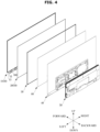
- FIG. 4 is a rear exploded perspective view illustrating a display apparatus according to an embodiment.
- the display apparatus 1 may include a display panel 10, a front chassis 30 extending along the circumference of the display panel 10 and provided to cover the side surface of the display panel 10, a rear chassis 40 provided to cover the rear surface of the display panel 10, and a rear cover 50 provided to cover a portion of the rear surface of the rear chassis 40.
- the display apparatus 1 may further include an inner plate 60 coupled to the front of the rear chassis 40 and provided to reinforce the strength of the rear chassis 40 and dissipate heat generated from the display panel 10.
- the display panel 10 may include a light-emissive panel 11 configured to emit light by itself to display an image and a heat dissipation sheet 20 attached to a rear surface of the light-emissive panel 11 and provided to emit heat.
- the heat dissipation sheet 20 may be provided in a size corresponding to that of the light-emissive panel 11, and may be attached to the rear surface of the light-emissive panel 11 by an adhesive member, such as an adhesive or double-sided tape.
- the light-emissive panel 11 may be configured to display an image using an organic light emitting device (OLED).
- OLED organic light emitting device
- the light-emissive panel 11, which does not include a backlight unit at the rear side thereof, may have a smaller thickness than a light-receiving panel.
- a film cable 12 may be provided at a lower end of the light-emissive panel 11.
- the film cable 12 may be coupled to the light-emissive panel 11 in the form of a Chip On Film (COF).
- COF Chip On Film
- the film cable 12 may be formed of a flexible material to enable bending.
- One end of the film cable 12 may be connected to the lower end of the light-emissive panel 11, and the other end of the film cable 12 may be bent to be provided adjacent to the rear surface of the heat dissipation sheet 20.
- a substrate 13 may be provided at the other end of the film cable 12.
- the substrate 13 may be configured to send a signal to drive the light-emissive panel 11.
- the substrate 13 may be coupled to the rear surface of the heat dissipation sheet 20.
- the substrate 13 may be attached to the rear surface of the heat dissipation sheet 20 by an adhesive member, such as an adhesive or double-sided tape.
- the number of the substrates 13 may vary according to the size of the light-emissive panel 11. As the size of the light-emissive panel 11 increases, the number of the substrates 13 may increase.
- the display apparatus 1 may include a connecting cable 13 provided to connect two substrates 13 adjacent to each other. According to an embodiment, the display apparatus 1 may include four substrates 13, a connecting cable 13 connecting two of the four substrates 13, and a connecting cable 13 connecting the remaining two substrates 13.
- the heat dissipation sheet 20 may be attached to the rear surface of the light-emissive panel 11 to dissipate heat.
- the heat dissipation sheet 20 may increase a contact area with the light-emissive panel 11 to effectively absorb heat from the light-emissive panel 11.
- the heat dissipation sheet 20 and the light-emissive panel 11 may be coupled to each other by an adhesive member.
- the heat dissipation sheet 20 may include at least one of graphite, aluminum, or copper. Preferably, the heat dissipation sheet 20 may include graphite.
- the heat dissipation sheet 20 may be provided to be detachable from the rear chassis 40.
- the heat dissipation sheet 20 may not be coupled to the rear chassis 40. Accordingly, the heat dissipation sheet 20 may be separated from the rear chassis 40 without any limitation.
- the front chassis 30 may be provided to cover the side surface of the display panel 10.
- the front chassis 30 may be formed to extend along the circumference of the display panel 10. Accordingly, the front chassis 30 may be provided in a substantially square ring shape.
- the rear chassis 40 may be provided to have a size corresponding to that of the display panel 10.
- the rear chassis 40 may be provided to cover the rear surface of the display panel 10. As described above, the rear chassis 40 may form a rear external appearance of the display apparatus 1 together with the rear cover 50.
- the inner plate 60 may have a size corresponding to that of the rear chassis 40 and may be coupled to the front surface of the rear chassis 40.
- the inner plate 60 may be provided to be coupled to the rear chassis 40 to reinforce rigidity of the rear chassis 40 and dissipate heat generated from the display panel 10.
- the rear cover 50 may be provided to cover a portion of the rear surface of the rear chassis 40.
- the rear cover 50 may be coupled to the rear surface of the rear chassis 40 to form an inner space.
- a T-con board (a timing controller), a main board, a power supply, etc. may be provided.
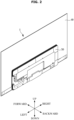
- FIG. 5 is a rear view illustrating a display apparatus according to an embodiment with a rear cover removed.
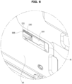
- FIG. 6 is an enlarged view of portion A of FIG. 5 , seen from a different angle.
- FIG. 7 is a view illustrating a state of FIG. 6 , with a wire separated.
- a user may easily withdraw a wire 130 without a separate member.
- the wire 130 is a component that couples a panel holder 100 to a support frame 110 to be described below, and as the wire 130 is drawn out, the coupling between the panel holder 100 and the support frame 110 may be released.
- a chassis hole 41 may be exposed to the outside.
- the rear chassis 40 may include the chassis hole 41 through which the wire 130 passes.
- the chassis hole 41 may be covered by the rear cover 50.
- the chassis hole 41 may be provided in an area of the rear chassis 40 covered by the rear cover 50.
- the wire 130 may be provided to be accessible from the rear side of the rear chassis 40. At least a portion of the wire 130 may be exposed to the outside through the chassis hole 41 of the rear chassis 40.
- the user may separate the wire 130 from the display apparatus 1 to release the coupling between the display panel 10 and the rear chassis 40.
- the wire 130 may be drawn out to the rear of the rear chassis 40 through the chassis hole 41.
- the wire 130 may be moved to a lateral side to be drawn out of the display apparatus 1.
- the wire 130 may be drawn out of the rear chassis 40 by passing through the chassis hole 41.
- a bent end 131 of the wire 130 may be inserted into a wire hole 108 of the panel holder 100. After the bent end 131 of the wire 130 is drawn out from the wire hole 108, the wire 130 may be pulled to a lateral side to be drawn out of the display apparatus 1. As the wire 130 is drawn out of the display apparatus 1, the coupling between the panel holder 100 and the support frame 110 may be released.
- the panel holder 100 and the support frame 110 coupled by the wire 130 may be provided on each side of the rear surface of the display panel 10.
- a bottom frame 70 may be provided between a pair of panel holders 100 and a pair of support frames 110.
- the bottom frame 70 may be provided at a central lower portion of the rear chassis 40.
- the bottom frame 70 may be provided with a fastening hole 71 which a fastening member, such as a screw, passes through. Since the fastening hole 71 of the bottom frame 70 is covered by the rear cover 50, the lower end of the display panel 10 may be coupled to the lower end of the rear chassis 40 using a fastening member, such as a screw, as in the related art.
- the rear chassis 40 forms the rear external appearance of the display apparatus 1.
- a fastening hole or the like may not be provided in the rear chassis 40 exposed to the outside.
- both side ends of the rear chassis 40 are detachably coupled to both side ends of the display panel 10 corresponding thereto without including a fastening hole. More specifically, as the panel holder 100 coupled to the rear surface of the display panel 10 and the support frame 110 coupled to the front surface of the rear chassis 40 are coupled to and released from each other, the display panel 10 may be coupled to or detached from the rear chassis 40.
- FIG. 8 is a view illustrating a display panel and a rear chassis separated from a display apparatus according to an embodiment.
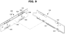
- FIG. 9 is a view separately illustrating a panel holder and a support frame of a display apparatus according to an embodiment.
- FIG. 10 is a view illustrating a panel holder and a wire coupled to the panel holder in a display apparatus according to an embodiment.
- FIG. 11 is a view illustrating a panel holder and a support frame coupled by a wire in a display apparatus according to an embodiment.
- FIG. 12 is a front view illustrating a panel holder and a support frame coupled by a wire
- the panel holder 100 may be coupled to the rear surface of the display panel 10. More specifically, the panel holder 100 may be attached to the rear surface of the display panel 10 by an adhesive member 107 provided between film cables 12 adjacent to each other.
- the adhesive member 107 may be provided on the lateral side of the film cable 12.
- the adhesive member 107 may include an adhesive and a double-sided tape.
- the type of the adhesive member 107 is not limited and may be any configuration capable of attaching the panel holder 100 to the rear surface of the display panel 10.
- the panel holder 100 may be provided adjacent to the lower end of the display panel 10.
- the panel holders 100 may be provided as a pair and provided on one side and the other side of the display panel 10, respectively.
- the support frame 110 may be coupled to the front surface of the rear chassis 40 to correspond to the panel holder 100.
- the support frame 110 may be provided adjacent to the lower end of the rear chassis 40.
- the support frame 110 may be provided as a pair and provided on one side and the other side of the rear chassis 40, respectively.
- the wire 130 may be coupled to the panel holder 100.
- the wire 130 may be coupled to the panel holder 100 by traversing the panel holder 100 sideways.
- the wire 130 may pass through a second hole 104 of the panel holder 100 to be accommodated in a wire accommodating groove 103 so that the wire 130 is coupled to the panel holder 100.
- the bent end 131 of the wire 130 may be inserted into the wire hole 108 of the panel holder 100 so that the position of the wire 130 is fixed. By the bent end 131 of the wire 130 being inserted into the wire hole 108, the wire 130 may maintain a state of being coupled to the panel holder 100.
- the panel holder 100 includes a plate-shaped holder body 101, and a first hole 102, a second hole 104, and a third hole 105 formed to pass through the holder body 101.
- the panel holder 100 may include the wire accommodating groove 103 provided to accommodate the wire 130 and a protrusion support 106 provided to come in contact with a second protrusion 113 of the support frame 110.
- the panel holder 100 may include the wire hole 108 in to which the bent end of the wire 130 is inserted.
- the support frame 110 may include a plate-shaped frame body 111, a first protrusion 112 protruding from the frame body 111 toward the panel holder 100, and a second protrusion 113 spaced downward from the first protrusion 112.
- the first protrusion 112 may be provided to be inserted into the first hole 102 of the panel holder 100, and come in contact with a first portion of the wire 130 to support the first portion.
- the second protrusion 113 may be provided to be inserted into the third hole 105 of the panel holder 100 to engage with the protrusion support 106 of the panel holder 100. As the second protrusion 113 and the protrusion support 106 are engaged with each other, the panel holder 100 may not be separated from the support frame 110 in the forward direction.
- the panel holder 100 and the support frame 110 may be coupled to each other by the wire 130.
- the panel holder 100 may be restricted from moving forward of the support frame 110.
- the panel holder 100 may be separable from the support frame 110 in the forward direction.
- the wire 130 may be coupled to the panel holder 100 and the support frame 110. In other words, the wire 130 may be positioned between the panel holder 100 and the support frame 110.
- the wire 130 When the wire 130 is coupled to the panel holder 100 and the support frame 110, upward movement of the panel holder 100 with respect to the support frame 110 may be restricted.
- the panel holder 100 and the support frame 110 may be fixed without being moved in the front-rear direction.
- the first portion of the wire 130 may be supported by the first protrusion 112 of the support frame 110, and the second portion of the wire 130 may be accommodated in the wire accommodating groove 103.
- the second portion of the wire 130 may be supported by one surface of the panel holder 100 forming the wire accommodating groove 103.
- the second portion of the wire 130 may indicate a pair of points provided on both sides of the first portion of the wire 130.
- the first protrusion 112 supporting the first portion of the wire 130 may be spaced apart from the wire accommodating groove 103 supporting the second portion of the wire 130 in the front-rear direction.
- the wire 130 may be bent.
- the panel holder 100 may be coupled to the support frame 110 by the tension of the wire 130 without a gap in the front-rear direction.
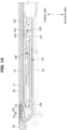
- FIG. 13 is a cross-sectional view taken along line B-B of FIG. 11 , which shows a display panel and a rear chassis.
- the panel holder 100 may be coupled to the support frame 110 without a gap in the front-rear direction as described above. Since the panel holder 100 is coupled to the display panel 10 and the support frame 110 is coupled to the rear chassis 40, the coupling of the panel holder 100 to the support frame 110 allows the display panel 10 to be coupled to the rear chassis 40.
- FIG. 14 is a view illustrating a state before a panel holder and a wire coupled to the panel holder are coupled to a support frame.
- FIG. 15 is a view illustrating a process in which a panel holder and a wire coupled to the panel holder are coupled to a support frame.
- FIG. 16 is a view illustrating a state after a panel holder and a wire coupled to the panel holder are coupled to a support frame.
- the display panel 10 when the panel holder 100 is coupled to the support frame 110, the display panel 10 may not be coupled to the panel holder 100. According to an embodiment, after the panel holder 100 is coupled to the support frame 110, the display panel 10 may be coupled to the panel holder 100.
- the wire 130 may be coupled to the panel holder 100 first. With the wire 130 coupled to the panel holder 100, the panel holder 100 may be coupled to the support frame 110.
- the panel holder 100 may be moved for the first portion of the wire 130 to be positioned below the first protrusion 112.
- the first portion of the wire 130 may be positioned below the first protrusion 112.
- the panel holder 100 may be rotated by a predetermined angle using the wire 130 as a rotation axis.
- the protrusion support 106 may be positioned below the second protrusion 113.
- the wire 130 is bent, and tension of the wire 130 may be applied to move the panel holder 100 downward with respect to the support frame 110.
- the panel holder 100 may be moved downward with respect to the support frame 110 by the tension of the wire 130.
- the second protrusion 113 and the protrusion support 106 may be engaged with each other.
- the panel holder 100 may not be separated from the support frame 110.
- the panel holder 100 may not be moved upwards of the support frame 110 due to the tension of the wire 130. Accordingly, the panel holder 100 and the support frame 110 may be maintained in a coupled state.
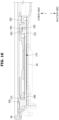
- FIG. 17 is a cross-sectional view taken along line C-C of FIG. 11 with a wire removed, which shows a display panel and a rear chassis.
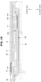
- FIG. 18 is a view illustrating a state of FIG. 17 with a panel holder moved upward with respect to a support frame.
- FIG. 19 is a view illustrating a state after a panel holder is separated from a support frame to the front.
- the panel holder 100 may be separated from the support frame 110 without a separate member.
- the display panel 10 may be separated from the rear chassis 40.
- the wire 130 may be drawn out of the display apparatus 1 through the chassis hole 41 from the rear side of the rear chassis 40.
- the display panel 10 and the substrate 13 attached to the display panel 10 may be separated from the rear chassis 40 without damage to the display panel 10.
- adhesive members may be provided on the upper surface and both side surfaces of the display panel 10 to couple the upper surface and both side surfaces of the display panel 10 to the rear chassis 40.
- the type of the adhesive member is not limited, but may be, for example, a double-sided tape.
- the display panel 10 When the adhesive members provided on the upper surface and both side surfaces of the display panel 10 are separated, and then the panel holder 100 provided on the lower surface of the display panel 10 is separated from the support frame 110, the display panel 10 may be separated from the rear chassis 40 without damaging the display panel 10.
- the couplings on the four sides of the display panel 10 are removed, since the rear surface of the heat dissipation sheet 20 and the front surface of the rear chassis 40 are separable from each other as described above, the display panel 1 may be separable from the rear chassis 40 in the forward direction. Accordingly, it is possible to disassemble and replace the display panel 10 including the light-emissive panel 11.
- FIG. 20 is a view illustrating a display panel and a rear chassis separated from a display apparatus according to an embodiment.
- FIG. 21 is a view separately illustrating a panel holder and a support frame in a display apparatus according to an embodiment.
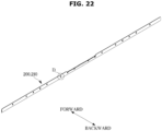
- FIG. 22 is a view illustrating a state in which a panel holder and a support frame shown in FIG. 21 are coupled to each other.
- a panel holder 200 and a support frame 210 may be coupled to and separated from each other by sliding movement without a wire or a separate member.
- the panel holder 200 may be coupled to the support frame 210 by slidably moving with respect to the support frame 210 in the first direction. Conversely, the panel holder 200 may be separated from the support frame 210 by slidably moving with respect to the support frame 210 in the second direction opposite to the first direction.
- the first direction may refer to the downward direction
- the second direction may refer to the upward direction.
- the panel holder 200 may be coupled to the lower end of the rear surface of the display panel 10.
- the support frame 210 may be coupled to the lower end of the front surface of the rear chassis 40. By moving the display panel 10 upward with respect to the rear chassis 40, the display panel 10 may be separated from the rear chassis 40 in the forward direction.
- FIG. 23 is an enlarged view of portion D of FIG. 22 , showing a state in which a panel holder and a support frame are coupled to each other.
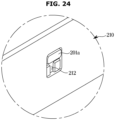
- FIG. 24 is an enlarged view of portion D of FIG. 22 , showing a state in which a panel holder and a support frame are in a state of being separable from each other.
- FIG. 25 is a cross-sectional perspective view of FIG. 23 .
- FIG. 26 is a cross-sectional perspective view of FIG. 24 .
- the panel holder 200 may include coupling protrusions 201 protruding toward the support frame 210.
- the coupling protrusions 201 include a head portion 201A having a first area and a connecting portion 201B having a second area smaller than the first area and connecting the head portion 201 to the panel holder 200.
- the support frame 210 may include a first hole 211 having an area larger than the first area so that the head portion 201A of the panel holder 200 may pass through the first hole 211, and a second hole 212 having an area smaller than the first area and larger than the second area.
- the first hole 211 and the second hole 212 may be consecutively arranged in the vertical direction.
- the head portion 201A of the coupling protrusions 201 may be inserted into the first hole 211.
- the head portion 201A inserted into the first hole 211 may slide downward.
- the connecting portion 201B is inserted into the second hole 212, and because the head portion 201A does not pass through the second hole 212, the panel holder 200 and the support frame 210 may be coupled to each other.
Landscapes
- Engineering & Computer Science (AREA)
- Theoretical Computer Science (AREA)
- Physics & Mathematics (AREA)
- Microelectronics & Electronic Packaging (AREA)
- General Engineering & Computer Science (AREA)
- General Physics & Mathematics (AREA)
- Human Computer Interaction (AREA)
- Thermal Sciences (AREA)
- Computer Hardware Design (AREA)
- Devices For Indicating Variable Information By Combining Individual Elements (AREA)
Applications Claiming Priority (2)
| Application Number | Priority Date | Filing Date | Title |
|---|---|---|---|
| KR1020210168000A KR20230080642A (ko) | 2021-11-30 | 2021-11-30 | 디스플레이 장치 |
| PCT/KR2022/012327 WO2023101143A1 (ko) | 2021-11-30 | 2022-08-18 | 디스플레이 장치 |
Publications (2)
| Publication Number | Publication Date |
|---|---|
| EP4346342A1 true EP4346342A1 (de) | 2024-04-03 |
| EP4346342A4 EP4346342A4 (de) | 2024-12-25 |
Family
ID=86499917
Family Applications (1)
| Application Number | Title | Priority Date | Filing Date |
|---|---|---|---|
| EP22901503.7A Pending EP4346342A4 (de) | 2021-11-30 | 2022-08-18 | Anzeigegerät |
Country Status (3)
| Country | Link |
|---|---|
| US (2) | US12265419B2 (de) |
| EP (1) | EP4346342A4 (de) |
| CN (1) | CN117769893A (de) |
Families Citing this family (7)
| Publication number | Priority date | Publication date | Assignee | Title |
|---|---|---|---|---|
| USD1052551S1 (en) * | 2021-10-15 | 2024-11-26 | Samsung Electronics Co., Ltd. | Television receiver |
| USD1035601S1 (en) * | 2021-12-16 | 2024-07-16 | Samsung Electronics Co., Ltd. | Television receiver |
| USD1080569S1 (en) * | 2022-01-04 | 2025-06-24 | Samsung Electronics Co., Ltd. | Television |
| USD1085034S1 (en) * | 2022-01-04 | 2025-07-22 | Samsung Electronics Co., Ltd. | Television |
| USD1085032S1 (en) * | 2022-01-04 | 2025-07-22 | Samsung Electronics Co., Ltd. | Television |
| USD1085033S1 (en) * | 2022-01-04 | 2025-07-22 | Samsung Electronics Co., Ltd. | Television |
| USD1076842S1 (en) * | 2022-01-04 | 2025-05-27 | Samsung Electronics Co., Ltd. | Television |
Family Cites Families (20)
| Publication number | Priority date | Publication date | Assignee | Title |
|---|---|---|---|---|
| JP2003288028A (ja) | 2001-12-25 | 2003-10-10 | Canon Inc | 画像表示装置の分解方法、画像表示装置の製造方法、支持体の製造方法、画像表示部の製造方法、加工材料の製造方法、および画像表示装置 |
| US7931771B2 (en) | 2003-04-02 | 2011-04-26 | Panasonic Corporation | Method of manufacturing plasma display device |
| KR20060080721A (ko) * | 2005-01-06 | 2006-07-11 | 삼성에스디아이 주식회사 | 플라즈마 디스플레이 모듈 |
| JP4431615B2 (ja) | 2005-07-11 | 2010-03-17 | 日立プラズマディスプレイ株式会社 | 平面表示装置 |
| JP2007079098A (ja) | 2005-09-14 | 2007-03-29 | Matsushita Electric Ind Co Ltd | プラズマディスプレイ装置 |
| EP1895386A1 (de) * | 2006-08-31 | 2008-03-05 | TCL Thomson Electronics Europe SAS | Flachbildschirmanordnung |
| KR20070073971A (ko) | 2007-06-07 | 2007-07-10 | 후지츠 히다찌 플라즈마 디스플레이 리미티드 | 평면 표시 장치 |
| JP2009162869A (ja) | 2007-12-28 | 2009-07-23 | Hitachi Ltd | プラズマディスプレイパネルモジュール及びプラズマディスプレイ装置 |
| CN201368949Y (zh) * | 2008-08-26 | 2009-12-23 | 深圳Tcl新技术有限公司 | 平板显示屏装配结构 |
| JP5166613B1 (ja) | 2012-01-31 | 2013-03-21 | シャープ株式会社 | 表示装置、及びテレビジョン受信機 |
| US20140036162A1 (en) * | 2012-07-31 | 2014-02-06 | Kabushiki Kaisha Toshiba | Television receiver and electronic device |
| JP5827189B2 (ja) | 2012-08-10 | 2015-12-02 | 株式会社デジタル | 表示装置 |
| KR20150012982A (ko) * | 2013-07-25 | 2015-02-04 | 삼성전자주식회사 | 디스플레이장치 및 그 제어방법 |
| CN104464530B (zh) | 2014-11-18 | 2017-08-25 | 深圳市华星光电技术有限公司 | 曲面型显示装置 |
| KR102131661B1 (ko) * | 2015-12-04 | 2020-07-08 | 삼성전자주식회사 | 디스플레이 장치 |
| KR102391216B1 (ko) * | 2017-10-30 | 2022-04-27 | 엘지디스플레이 주식회사 | 디스플레이 장치 |
| KR101947693B1 (ko) * | 2018-04-13 | 2019-05-02 | 엘지전자 주식회사 | 디스플레이 장치 및 이를 포함하는 디스플레이 장치 분리 시스템 |
| KR102730876B1 (ko) | 2019-06-04 | 2024-11-18 | 삼성전자주식회사 | 디스플레이 장치 |
| KR102793978B1 (ko) | 2019-08-08 | 2025-04-14 | 삼성전자주식회사 | 디스플레이 모듈, 디스플레이 패널, 및 디스플레이 장치 |
| KR102778627B1 (ko) | 2019-09-09 | 2025-03-07 | 엘지디스플레이 주식회사 | 표시장치 |
-
2022
- 2022-08-18 EP EP22901503.7A patent/EP4346342A4/de active Pending
- 2022-08-18 CN CN202280051707.8A patent/CN117769893A/zh active Pending
- 2022-08-24 US US17/894,702 patent/US12265419B2/en active Active
-
2025
- 2025-02-26 US US19/063,644 patent/US20250199569A1/en active Pending
Also Published As
| Publication number | Publication date |
|---|---|
| US20230168712A1 (en) | 2023-06-01 |
| EP4346342A4 (de) | 2024-12-25 |
| CN117769893A (zh) | 2024-03-26 |
| US12265419B2 (en) | 2025-04-01 |
| US20250199569A1 (en) | 2025-06-19 |
Similar Documents
| Publication | Publication Date | Title |
|---|---|---|
| US12265419B2 (en) | Display apparatus | |
| EP4422373B1 (de) | Anzeigevorrichtung | |
| KR102116932B1 (ko) | 인쇄회로기판 장착 구조 및 이를 포함하는 디스플레이 장치 | |
| US9804429B2 (en) | Display apparatus | |
| KR102959447B1 (ko) | 디스플레이 장치 | |
| US11687122B2 (en) | Display device | |
| US20250093692A1 (en) | Display device | |
| KR20230080642A (ko) | 디스플레이 장치 | |
| US20240244777A1 (en) | Display apparatus | |
| KR101947693B1 (ko) | 디스플레이 장치 및 이를 포함하는 디스플레이 장치 분리 시스템 | |
| US11092831B2 (en) | Image display apparatus | |
| EP3343276B1 (de) | Anzeigegerät | |
| CN115561928B (zh) | 一种面框、背板和大屏显示设备 | |
| US20250264187A1 (en) | Stand for display apparatus and display apparatus including same | |
| US20240306325A1 (en) | Display apparatus | |
| KR20240138425A (ko) | 디스플레이 장치 | |
| KR20250125224A (ko) | 디스플레이 장치 | |
| CN216052510U (zh) | 显示装置 | |
| KR20260045994A (ko) | 디스플레이 장치 | |
| CN214427736U (zh) | 投影幕组件及投影设备 | |
| KR20230080727A (ko) | 디스플레이 장치 및 그 제조방법 | |
| KR101557110B1 (ko) | 하우징, 이를 포함하는 디스플레이 장치, 테이핑 부재 및 이를 이용하는 하우징 체결 방법 | |
| KR100710331B1 (ko) | 영상표시장치 | |
| KR20260061981A (ko) | 디스플레이 장치 | |
| CN120202372A (zh) | 支架和显示设备 |
Legal Events
| Date | Code | Title | Description |
|---|---|---|---|
| STAA | Information on the status of an ep patent application or granted ep patent |
Free format text: STATUS: THE INTERNATIONAL PUBLICATION HAS BEEN MADE |
|
| PUAI | Public reference made under article 153(3) epc to a published international application that has entered the european phase |
Free format text: ORIGINAL CODE: 0009012 |
|
| STAA | Information on the status of an ep patent application or granted ep patent |
Free format text: STATUS: REQUEST FOR EXAMINATION WAS MADE |
|
| 17P | Request for examination filed |
Effective date: 20231227 |
|
| AK | Designated contracting states |
Kind code of ref document: A1 Designated state(s): AL AT BE BG CH CY CZ DE DK EE ES FI FR GB GR HR HU IE IS IT LI LT LU LV MC MK MT NL NO PL PT RO RS SE SI SK SM TR |
|
| REG | Reference to a national code |
Ref country code: DE Ref legal event code: R079 Free format text: PREVIOUS MAIN CLASS: H05K0005000000 Ipc: G06F0001160000 |
|
| A4 | Supplementary search report drawn up and despatched |
Effective date: 20241127 |
|
| RIC1 | Information provided on ipc code assigned before grant |
Ipc: G09F 9/30 20060101ALI20241121BHEP Ipc: H05K 7/20 20060101ALI20241121BHEP Ipc: H05K 5/03 20060101ALI20241121BHEP Ipc: H05K 5/00 20060101ALI20241121BHEP Ipc: G06F 1/20 20060101ALI20241121BHEP Ipc: G06F 1/16 20060101AFI20241121BHEP |
|
| DAV | Request for validation of the european patent (deleted) | ||
| DAX | Request for extension of the european patent (deleted) |