EP4346475B1 - Appareil et procédé de fabrication de vêtements d'isolation fermés dans le dos à pièces multiples - Google Patents
Appareil et procédé de fabrication de vêtements d'isolation fermés dans le dos à pièces multiples Download PDFInfo
- Publication number
- EP4346475B1 EP4346475B1 EP22732762.4A EP22732762A EP4346475B1 EP 4346475 B1 EP4346475 B1 EP 4346475B1 EP 22732762 A EP22732762 A EP 22732762A EP 4346475 B1 EP4346475 B1 EP 4346475B1
- Authority
- EP
- European Patent Office
- Prior art keywords
- web
- continuous
- torso
- shoulder
- unit
- Prior art date
- Legal status (The legal status is an assumption and is not a legal conclusion. Google has not performed a legal analysis and makes no representation as to the accuracy of the status listed.)
- Active
Links
Images


Classifications
-
- A—HUMAN NECESSITIES
- A41—WEARING APPAREL
- A41D—OUTERWEAR; PROTECTIVE GARMENTS; ACCESSORIES
- A41D13/00—Professional, industrial or sporting protective garments, e.g. surgeons' gowns or garments protecting against blows or punches
- A41D13/12—Surgeons' or patients' gowns or dresses
- A41D13/1209—Surgeons' gowns or dresses
-
- A—HUMAN NECESSITIES
- A41—WEARING APPAREL
- A41D—OUTERWEAR; PROTECTIVE GARMENTS; ACCESSORIES
- A41D13/00—Professional, industrial or sporting protective garments, e.g. surgeons' gowns or garments protecting against blows or punches
- A41D13/12—Surgeons' or patients' gowns or dresses
- A41D13/1236—Patients' garments
- A41D13/1245—Patients' garments for the upper part of the body
-
- A—HUMAN NECESSITIES
- A41—WEARING APPAREL
- A41H—APPLIANCES OR METHODS FOR MAKING CLOTHES, e.g. FOR DRESS-MAKING OR FOR TAILORING, NOT OTHERWISE PROVIDED FOR
- A41H42/00—Multi-step production lines for making clothes
-
- A—HUMAN NECESSITIES
- A41—WEARING APPAREL
- A41D—OUTERWEAR; PROTECTIVE GARMENTS; ACCESSORIES
- A41D2300/00—Details of garments
- A41D2300/30—Closures
- A41D2300/328—Closures using adhesive
Definitions
- Embodiments of the present invention relate to isolation garments and, more particularly, to multi-piece closed-back/tube-style isolation garments.
- Isolation garments are useful in protecting the individuals wearing them from hostile environments. For example, hospital staff, patients, and visitors may wear isolation garments to avoid exposure to blood, other body fluids, and infectious materials or to protect patients, especially those with weakened immune systems, from infection. Also, individuals working in industrial facilities may wear isolation garments to prevent contact with hazardous chemicals. However, isolation garments may be worn in other conditions as well, especially in light of requirements imposed by some jurisdictions to prevent exposure to coronavirus disease 2019 (COVID-19). As an example, hair dressers or barbers may be required to wear isolation garments during their appointments.
- COVID-19 coronavirus disease 2019
- an automated system combines material webs to construct a portion of an isolation gown.
- the product produced by the automated system does not include sleeves and is not folded.
- the isolation garment is finished by hand, with sleeves being sown onto the initial product and then folded for packaging. This method results in a slow production speed and involves a high level of manual labor input.
- Another method involves producing isolation garments using a sequential or noncontinuous operation. That is, cutting the material webs, combining the webs, and folding of the webs are all performed at different stations. Therefore, the isolation garments must be constantly transferred between the stations in their various stages of production. Further, the combining of the webs and the folding and packaging of the resulting isolation garment is performed by hand. As such, this method is also slow and requires much manual labor.
- Still another method that involves a high degree of manual input is one in which an individual cuts the shape of an isolation garment out of one material web or out a stack of material webs. The rest of the material web is discarded as scrap. Thereafter, the material webs are bonded, folded, and packaged manually. The end result is a plurality of isolation garments produced by a slow, manual method that produces a large amount of wasted raw material.
- FR2171386 (A1 ) discloses an article for clothing particularly a blouse, dress or shirt for limited use, which is made from foldable sheet material, e.g.
- paper consists of (a) an upper part comprising the shoulders, sleeves and neck opening and formed by folding the sheet material, aligning the edges with each other and fixing these edges to close the sleeve, and (b) a lower part forming the body part, open at the bottom and formed by folding a sheet of material and aligning the edges.
- isolation garments that can produce isolation garments quickly and do not depend on a high level of manual input or result in a large amount of raw material scrap.
- an apparatus for manufacturing multi-piece closed-back isolation garments includes a die unit configured to cut neck openings in a continuous shoulder web having a first edge and a second edge opposite the first edge, a first adhesive applicator configured to apply a plurality of first adhesive strips on the continuous shoulder web adjacent to the first edge of the continuous shoulder web, and a transfer unit configured to transfer torso web pieces having a substantially tubular shape onto each first adhesive strip such that a first edge of the torso web piece is overlapping the first edge of the continuous shoulder web.
- the apparatus further includes a second adhesive applicator configured to apply a plurality of second adhesive strips on each torso web piece adjacent to the first edge of each torso web piece, a first folding unit configured to fold the continuous shoulder web such that the second edge of the continuous shoulder web overlaps each second adhesive strip to form first shoulder web panels and second shoulder web panels overlapping each other in the continuous shoulder web, and a bonding unit configured to create underarm seams between first shoulder web panels and second shoulder web panels overlapping each other in the continuous shoulder web to form shoulder web pieces.
- a second adhesive applicator configured to apply a plurality of second adhesive strips on each torso web piece adjacent to the first edge of each torso web piece
- a first folding unit configured to fold the continuous shoulder web such that the second edge of the continuous shoulder web overlaps each second adhesive strip to form first shoulder web panels and second shoulder web panels overlapping each other in the continuous shoulder web
- a bonding unit configured to create underarm seams between first shoulder web panels and second shoulder web panels overlapping each other in the continuous shoulder web to form shoulder
- a method of manufacturing multi-piece closed-back isolation garments includes cutting neck openings in a continuous shoulder web having a first edge and a second edge opposite the first edge with a first die unit, applying a plurality of first adhesive strips on the continuous shoulder web adjacent to the first edge of the continuous shoulder web with an adhesive applicator, and transferring, with a transfer unit, a torso web piece having a substantially tubular shape onto each first adhesive strip such that a first edge of the torso web piece is overlapping the first edge of the continuous shoulder web.
- the method also includes applying a plurality of second adhesive strips on each torso web piece adjacent to the first edge of each torso web piece, folding the continuous shoulder web with a folding unit such that the second edge of the continuous shoulder web overlaps each second adhesive strip to form first shoulder web panels and second shoulder web panels overlapping each other in the continuous shoulder web, and creating underarm seams between the first and second shoulder web panels using a first bonding unit to form shoulder web pieces.
- a multi-piece closed-back isolation garment includes a shoulder web piece having overlapping first and second shoulder web panels substantially aligned with each other, each of the first and second shoulder web panels having a bottom edge and a pair of underarm edges extending from the bottom edge; a pair of underarm seams joining the first and second shoulder web panels at adjacent underarm edges of the first and second shoulder web panels to form first and second sleeves in the shoulder web piece; and a neck opening formed in the first and second shoulder web panels opposite the bottom edges of the first and second shoulder web panels.
- the garment additionally includes a torso web piece having left and right side panel edges overlapping each other to form a substantially tubular shape and a top edge overlapping the bottom edges of the first and second shoulder web panels of the shoulder web piece.
- the garment includes a first adhesive strip attaching the torso web piece to the first shoulder web panel of the shoulder web piece and a second adhesive strip coupling the torso web piece to the second shoulder web panel of the shoulder web piece.
- first and second shoulder web panels are integral with each other and share a folded top edge in which the neck opening is located.
- the first shoulder web panel is separate from second shoulder web panel such that the first and second shoulder web panels comprise separate top edges and the first and second shoulder web panels are attached via at least one seam formed adjacent the top edges of the first and second shoulder web panels.
- the torso web piece includes folded left and right side edges positioned between the folded left and right side edge pieces.
- the torso web piece includes at least one perforation line defining at least one tie strap that is at least partially separable from the torso web piece.
- Embodiments of the present invention provide for an apparatus and method of manufacturing multi-piece closed-back/tube-style isolation garments.
- the apparatus utilizes a series of cutting, folding, bonding, and transfer units. These units operate together to create torso web pieces from at least one continuous torso web, combine the discrete torso pieces with a continuous shoulder web, cut the combined torso and shoulder web structure to form the multi-piece closed-back isolation garments, and fold or roll up the multi-piece closed-back isolation garments for packaging.
- the multi-piece closed-back isolation garments may be used in a variety of environments such as, for example, as isolation gowns in medical environments, as an alternative to coveralls in industrial environments, and any other environments in which isolation from potentially hazardous or unclean materials or other individuals is desired.
- isolation gowns it is contemplated that the garments described herein may be manufactured for use outside of the healthcare industry.
- Isolation gown 10 includes a torso web piece 12 and a shoulder web piece 14.
- Torso and shoulder web pieces 12, 14 may include nonwoven materials, woven materials, films, foams, and/or composites or laminates of any of these material types.
- torso web piece 12 is shown as a single torso web panel that has been folded. Folded torso web piece 12 includes a top edge 16, a bottom edge 18, folded left side and right side edges 20, 22, and overlapping left and right side panel edges 24, 26, where panel edges 24, 26 are named for their locations prior to folding torso web piece 12.
- Edges 16, 18, 20, 22 define front and rear surfaces 23, 25 of torso web piece 12.
- Right side panel edge 26 is folded over left side panel edge 24 by an overlapping distance 90.
- left side panel edge 24 may be folded over right side panel edge 26 by overlapping distance 90.
- torso web piece 12 has a substantially tubular shape.
- torso web piece 12 may also be formed of two separate torso web panels (not shown). In that case, the two torso web panels would be bonded at their side edges to create side seams (not shown).
- the side seams may be created using a variety of different bonding techniques that attach together two or more material layers such as sonic, thermal, ultrasonic, pressure, or adhesive bonding techniques and various other forms of bonding known in the industry.
- Torso web piece 12 further includes two tie straps 86, 88.
- Tie strap 86 is positioned adjacent right side panel edge 26, and tie strap 88 is positioned adjacent tie strap 86.
- right side panel edge 26 is folded over left side panel edge 24 by an overlapping distance 90.
- tie strap 86 will be separated from tie strap 88 along a perforation line 92
- tie strap 88 will be separated from torso web piece 12 along a perforation line 94.
- both of tie straps 86, 88 will remain integrated with torso web piece 12 near top edge 16.
- Tie straps 86, 88 may be tied around a wearer of isolation gown 10 in order to keep isolation gown 10 close to the wearer and further prevent contact with possibly unsafe substances.
- Shoulder web piece 14 of isolation gown 10 includes overlapping front and rear shoulder web panels 38, 40.
- front and rear shoulder web panels 38, 40 share a folded top edge 42.
- front and rear shoulder web panels 38, 40 may also be formed from two discrete shoulder web panels with separate top edges (not shown) in an alternate embodiment.
- shoulder web piece 14 would include a seam (not shown) between shoulder web panels 38, 40 adjacent the two top edges.
- the seam between the two top edges may be created by a bonding technique such as, for example, sonic, thermal, ultrasonic, pressure, or adhesive bonding.
- top edge 42 includes a substantially centralized neck opening 44.
- Shoulder web piece 14 may also include one or multiple optional perforation line(s) 46 that extend down from neck opening 44 on rear shoulder web panel 40 such that a wearer of isolation gown 10 is able to tear apart a portion of rear shoulder web panel 40 to make neck opening 44 larger or to completely tear rear shoulder web panel 40 apart. Tearing apart rear shoulder web panel 40 may aid wearer in removing isolation gown 10 without being contaminated by a substance that landed on isolation gown 10 during a medical procedure or industrial activity, as non-limiting examples. A larger neck opening 44 may make a wearer more comfortable while wearing isolation gown 10.
- shoulder web piece 14 may also include optional thumb slits or holes 48, referred to hereafter as thumb openings 48, along top edge 42 in order to allow wearers of isolation gown 10 to insert their thumbs therethrough and have greater control over the movement of isolation gown 10.
- Front shoulder web panel 38 includes a front bottom edge 50 and two front underarm edges 52 extending from front bottom edge 50 toward top edge 42
- rear shoulder web panel 40 includes a rear bottom edge 54 and two rear underarm edges 56 extending from rear bottom edge 54 toward top edge 42 in approximately the same pattern as front underarm edges 52.
- Front and rear bottom edges 50, 54 and front and rear underarm edges 52, 56 are substantially aligned with each other.
- Shoulder web piece 14 includes underarm seams 58 joining front and rear shoulder web panels 38, 40 at adjacent front and rear underarm edges 52, 56 in order to create left and right sleeves 60, 62 having respective left and right wrist openings 64, 66 defined between underarm seams 58 and top edge 42.
- Underarm seams 58 may be created by a bonding technique such as sonic, thermal, ultrasonic, pressure, or adhesive bonding, as non-limiting examples.
- Front and rear shoulder web panels 38, 40 also include adhesive strips 68, 70 positioned on interior surfaces 72, 74 thereof.
- Adhesive strips 68, 70 are positioned adjacent front and rear bottom edges 50, 54 and facilitate the attachment of torso web piece 12 to shoulder web piece 14.
- Torso web piece 12 is positioned within shoulder web piece 14 such that top edge 16 of torso web piece 12 extends beyond front and rear bottom edges 50, 54 and adhesive strips 68, 70.
- Adhesive strip 68 is positioned between and bonds together interior surface 72 of front shoulder web panel 38 and front surface 23 of torso web piece 12.
- adhesive strip 70 is positioned between and bonds together interior surface 74 of rear shoulder web panel 40 and rear surface 25 of torso web piece 12.
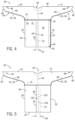
- isolation gowns 80, 82 are illustrated with alternative tie strap configurations to that of isolation gown 10 of FIGS. 1-3 , according other embodiments of the invention.
- Isolation gowns 80, 82 of FIGS. 4 and 5 respectively, include the same structure as that of isolation gown 10 of FIGS. 1-3 with the exception of the configuration of their tie straps. Since isolation gowns 80, 82 are arranged similarly to isolation gown 10 of FIGS. 1-3 , like elements in isolation gowns 80, 82 are numbered identically to corresponding elements in isolation gown 10.
- isolation gown 80 includes shoulder web piece 14 similar to that of FIG. 1 and a folded torso piece 84 including top edge 16, bottom edge 18, folded left side and right side edges 20, 22, and overlapping left and right side panel edges 24, 26, where panel edges 24, 26 are named for their locations prior to folding torso web piece 12.
- Edges 16, 18, 20, 22 define front and rear surfaces 23, 25 of torso web piece 12.
- Right side panel edge 26 is folded over left side panel edge 24 by an overlapping distance 27.
- left side panel edge 24 may be folded over right side panel edge 26 by overlapping distance 27.
- torso web piece 84 has a substantially tubular shape.
- Torso web piece 84 of gown 80 further includes two tie straps 28, 30.
- Tie strap 28 is positioned along right side panel edge 26. When in use, tie strap 28 will be separated from torso web piece 84 along perforation line 32, but remain integrated with torso web piece 84 adjacent top edge 16.
- Tie strap 30 is positioned on rear surface 25 of torso web piece 84 along folded right side edge 22 and is coupled to rear surface 25 via a top, permanent adhesive strip 34 and a bottom, fugitive adhesive strip 36 adjacent to folded right side edge 22.
- tie strap 30 may be a strip of web material cut from torso web piece 84 before folding. In that case, tie strap 30 would have a length identical to that of folded right side edge 22.
- tie strap 30 may have a different length than that of folded right side edge 22.
- tie strap 30 When in use, tie strap 30 will be separated from torso web piece 84 at fugitive adhesive strip 36 and remain connected to torso web at permanent adhesive strip 34.
- Tie straps 28, 30 may be tied around a wearer of isolation gown 10 in order to keep isolation gown 10 close to the wearer and further prevent contact with possibly unsafe substances.
- the overlapping distance 27 of gown 80 may be less than overlapping distance 90 of gown 10 ( FIG. 1 ).
- torso web piece 84 of gown 80 of FIG. 4 may be formed from a narrower torso web panel than torso web piece 12 of gown 10 of FIG. 1 .
- torso web piece 84 may also be formed of two separate torso web panels (not shown). In that case, the two torso web panels would be bonded at their side edges to create side seams (not shown).
- the side seams may be created using a variety of different bonding techniques that attach together two or more material layers such as sonic, thermal, ultrasonic, pressure, or adhesive bonding techniques and various other forms of bonding known in the industry.
- Front and rear shoulder web panels 38, 40 of gown 80 also include adhesive strips 68, 70 positioned on interior surfaces 72, 74 thereof.
- Adhesive strips 68, 70 are positioned adjacent front and rear bottom edges 50, 54 and facilitate the attachment of torso web piece 84 to shoulder web piece 14.
- Torso web piece 84 is positioned within shoulder web piece 14 such that top edge 16 of torso web piece 84 extends beyond front and rear bottom edges 50, 54 and adhesive strips 68, 70.
- Adhesive strip 68 is positioned between and bonds together interior surface 72 of front shoulder web panel 38 and front surface 23 of torso web piece 84.
- adhesive strip 70 is positioned between and bonds together interior surface 74 of rear shoulder web panel 40 and rear surface 25 of torso web piece 84.
- Adhesive strip 70 also bonds tie strap 30 between interior surface 74 of rear shoulder web panel 40 and rear surface 25 of torso web piece along with adhesive strip 34.
- isolation gown 82 includes shoulder web piece 14 shown in FIG. 1 and a folded torso web piece 96 including top edge 16, bottom edge 18, folded left and right side edges 20, 22, and overlapping left and right side panel edges 24, 26.
- Torso web piece 96 also includes two tie straps 98, 100. Tie strap 98 is positioned adjacent right side panel edge 26, and tie strap 100 is positioned adjacent left side panel edge 24 inside of torso web piece 96. In torso web piece 96, right side panel edge 26 is folded over left side panel edge 24 by overlapping distance 90 in a similar manner to that of FIG. 4 .
- torso web piece 96 may be formed from a torso web panel with a substantially similar length to that of torso web piece 84 of FIG. 4 .
- tie strap 98 When in use, tie strap 98 will be separated from torso web piece 96 along a perforation line 102, but will remain integrated with torso web piece 96 adjacent top edge 16.
- tie strap 100 When in use, tie strap 100 will be separated from torso web piece 96 along a perforation line 104, but will remain integrated with torso web piece 96 adjacent top edge 16. Thereafter, left side panel edge 24 of torso web piece 96 will be where perforation line 104 was before the separation of tie strap 100.
- tie straps 98, 100 may be tied around a wearer of isolation gown 82 in order to keep isolation gown 82 close to the wearer and further prevent contact with possibly unsafe substances.
- FIG. 6 a rear perspective view of a multi-piece closed-back/tube-style isolation gowns 83 is illustrated according to an embodiment that does not include integrated tie straps.
- right side panel edge 26 overlaps left side panel edge 24, but neither edge 24, 26 includes perforation lines for tie straps.
- gown 83 may be packaged without tie straps or one or more separate, discrete tie strap strips may be included with gown 83 in the final packaging.
- Isolation gown 83 of FIG. 6 includes the same structure as that of isolation gown 10 of FIGS. 1-3 with the exception of the configuration of their tie straps. Since isolation gown 83 is otherwise arranged similarly to isolation gown 10 of FIGS. 1-5 , like elements in isolation gowns 80, 82 are numbered identically to corresponding elements in isolation gown 10 and a description thereof is not repeated herein.
- wrist openings 93, 95 are the arrangement of wrist openings 93, 95 in sleeves 60, 62, the addition of a neck stretch patch 97 over neck opening 44 in front and rear shoulder web panels 38, 40, and the addition of wrist stretch patches 99 over wrist openings 93, 95 in lieu of optional thumb openings 48. While depicted as being circular in shape, wrist openings 93, 95 may be square, rectangular, triangular or other shapes as dictated by design specifications.
- wrist openings 93, 95 are located along the top edge 42 of shoulder web piece 14.
- Neck stretch patch 97 is folded over top edge 42 across neck opening 44
- wrist stretch patches 99 are folded over top edge 42 across wrist openings 93, 95.
- shoulder web piece 91 of FIG. 8 wrist openings 93, 95 are located in front shoulder web panel 38 between top edge 42 and underarm seams 52, 56.
- Neck stretch patch 97 is folded over top edge 42 across neck opening 44, and wrist stretch patches 99 are positioned over wrist openings 93, 95 on front shoulder web panel 38.
- the difference between shoulder web piece 89 of FIG. 7 and shoulder web piece 91 of FIG. 8 is the location of wrist openings 93, 95 and wrist stretch patches 99.
- neck and wrist stretch patches 97, 99 function in the same way, as described below with respect to FIG. 9 .
- neck stretch patch 97 and wrist stretch patches 99 are illustrated in relation to shoulder web piece 14 and neck opening 44 and wrist openings 93, 95, respectively, of shoulder web pieces 89, 91 of FIGS. 7 and 8 during the manufacturing process, according to an embodiment of the invention.
- Neck stretch patch 97 includes a neck opening 101 therein smaller than neck opening 44 in shoulder web piece 14 shown in phantom.
- each wrist stretch patch 99 includes a wrist opening 103 therein smaller than wrist openings 93, 95, which are shown in phantom.
- Neck and wrist stretch patches 97, 99 are made of a stretchable material such as, for example, an elastic film, elastic adhesive, elastic composite, or elastic laminate.
- neck and wrist stretch patches 97, 99 are stretchable, a wearer's head and hands may still fit through the smaller neck and wrist holes 101, 103, respectfully. Thereafter, neck and wrist stretch patches 97, 99 contract onto the wearer's neck and wrists to create seals that may additionally protect against potentially hazardous, infectious, or unclean materials entering isolation gowns 85, 87. As such, the inclusion of neck and wrist stretch patches 97, 99 are beneficial to wearers of isolation gowns 85, 87.
- Isolation gown 105 includes an alternative shoulder web piece 107 in place of shoulder web piece 14 shown in FIG. 1 .
- Isolation gown 105 is illustrated as including torso web piece 12 having the tie strap configuration of FIG. 1 , but it is contemplated that other embodiments may include any of the alternative tie strap configurations illustrated in FIGS. 3-6 .
- shoulder web piece 107 is arranged similarly to shoulder web pieces 14, 89, 91 of FIGS. 1-8 , like elements in shoulder web piece 107 are numbered identically to corresponding elements in shoulder web pieces 14, 89, 91.
- shoulder web piece 107 differs from shoulder web piece 14 of FIGS. 1-6 in the application of neck stretch patch 97 over neck opening 44.
- shoulder web piece 107 differs from shoulder web pieces 89, 91 ( FIGS. 7 and 8 ) in that shoulder web piece 107 includes a different configuration of wrist stretch patches 109 applied over corresponding wrist openings 93 in sleeves 60, 62. Wrist stretch patches 109 are folded over top edge 42 across wrist openings 93, with wrist openings 93 provided facing the right and left edges of sleeves 60, 62. During the manufacturing process, wrist stretch patches 109 and wrist openings 93 are positioned to span two adjacent isolation gowns 105, as explained with respect to FIG. 11 below. While depicted as being oval in shape, wrist openings 93 may be square, rectangular, triangular or other shapes as dictated by design specifications.
- neck stretch patch 97 and wrist stretch patches 109 are illustrated in relation to neck opening 44 and wrist openings 93, respectively, of shoulder web piece 107 of FIG. 10 during the manufacturing process, according to an embodiment of the invention.
- Neck stretch patch 97 is arranged in the same manner as shown in FIG. 9 , with neck opening 101 smaller than neck opening 44 in shoulder web piece 14.
- Wrist stretch patches 109 may be made of a stretchable material such as, for example, an elastic film, elastic adhesive, elastic composite, or elastic laminate.
- isolation gown 105 After wearers of isolation gown 105 insert their heads and hands through the stretchable material of neck and wrist stretch patches 97, 109, respectively, neck and wrist stretch patches 97, 109 contract onto their necks and wrists to create seals to provide more protection from the intrusion of possibly hazardous, infection, or unclean materials into isolation gown 105.
- wrist stretch patches 109 provides an advantage during manufacturing. More specifically, as shown in FIG. 11 , a length 113 of wrist stretch patches 109 is equal to that of neck stretch patch 97. As such, wrist stretch patches 109 may be applied to shoulder web piece 14 with the same machine as that used to apply neck stretch patches 97. This will be discussed in further detail with respect to FIG. 21 below.
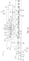
- FIG. 12 illustrates the machinery in manufacturing line 106 for performing a method of manufacturing multi-piece closed-back isolation gowns such as, for example, isolation gowns 10, 80, 82, 83 of FIGS. 1-6 .
- manufacturing line 106 may include additional machinery for forming isolation gowns 85, 87, 105 of FIGS. 7-11 , as will be discussed in more detail below with respect to FIGS. 19-21 .
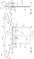
- the production flow 107 of FIG. 13 illustrates how webs may be manipulated and combined into multi-piece closed-back isolation gown 80 of FIG. 4 in manufacturing line 106. As such, like elements in FIGS. 1-11 are numbered identically to corresponding elements in FIGS. 12 and 13 .
- Manufacturing line 106 includes a torso web piece section 108 that forms one of torso web pieces 12, 84, 96, a shoulder web piece section 110 that forms shoulder web pieces 14, 89, 91, and an isolation gown section 112 that forms multi-piece closed-back isolation gowns 10, 80, 82, 83, 85, 87, 105 from one of torso web pieces 12, 84, 96 and shoulder web piece 14, 89, 91.
- manufacturing line 106 performs operations along a machine direction 114, but also performs operations in a cross-machine direction 116 that is perpendicular to machine direction 114.
- At least one continuous torso web 118 including a continuous left side panel edge 119 and a continuous right side panel edge 121 is fed into torso web piece section 108 in machine direction 114.
- Continuous torso web 118 may be fed into torso web piece section 108 via a turnbar infeed process during which continuous torso web 118 is unwound from a roll (not shown) and directed past at least one roller 120.
- Torso web piece section 108 will be in one of two configurations 123, 125 for processing continuous torso webs 118. In configuration 123, a single continuous torso web 118 is provided and folded. In alternative configuration 125 (shown in phantom), two separate continuous torso webs 118 are provided and bonded together.
- continuous torso web 118 is directed to an optional slitting unit 122.
- Slitting unit or apparatus 122 may include one or more knives or slitters (not shown) configured to cut at least one slit 124 in continuous torso web 118 in order to create one or more separated continuous tie strap webs 126 from continuous torso web 118. Thereafter, each separated continuous tie strap web 126 is directed away from continuous torso web 118 via a plurality of tie strap rollers 127.
- continuous tie strap web 126 may be fed via a material roll (not shown) separate from continuous torso web 118, in which case slitting unit 122 may be omitted.
- continuous torso web 118 may pass through an optional perforation unit or apparatus 128 including a rotary anvil 130 aligned with a rotary knife roll 132 having one or more knives 134.
- Each knife 134 may be positioned within an insert (not shown) on rotary knife roll 132 and arranged to align with a corresponding insert (not shown) inset within rotary anvil 130 during operation of perforation unit 128.
- Perforation unit 128 may be included in order to cut one or more perforation lines 136 in continuous torso web 118 in order to define one or more integral continuous tie strap webs 138.
- perforation lines 136 may become perforation line 32 in FIGS.
- tie strap 28 in FIGS. 1 and 3 perforation lines 92, 94 in FIG. 4 , or perforation lines 102, 104 in FIG. 5 in order to define tie strap 28 in FIGS. 1 and 3 , tie straps 86, 88 in FIG. 4 , or tie straps 98, 100 in FIG. 5 .
- Folding unit 140 may include folding boards, plow-style folding components, vacuum conveyors, and/or other known folding technologies and is configured to fold continuous torso web 118 in cross-direction 116 at each of continuous left and right side panel edges 119, 121 such that continuous right side panel edge 121 is folded over continuous left side panel edge 119, as shown in FIG. 13 .
- folding over continuous left side panel edge 119 occurs before folding over continuous right side panel edge 121.
- left side panel edge 119 may be folded over right side panel edge 121.
- continuous folded left and right side edges 142, 144 are formed.
- torso web piece section 108 will receive two continuous torso webs 118a, 118b in machine direction 114.
- Continuous torso web 118a will optionally pass through slitting and/or perforation unit or apparatus 122 configured to cut at least one continuous slit 124 and/or perforation line 136 in continuous torso web 118a in order to create one or more separated continuous tie strap webs 126 or integrated continuous tie strap webs 138. Thereafter, each separated continuous tie strap web 126 is directed away from continuous torso web 118a, and continuous torso web 118a is laid over continuous torso web 118b.
- configuration 125 utilizes two continuous torso webs 118a, 118b rather than a single continuous torso web 118, continuous torso webs 118a, 118b may be much narrower than continuous torso web 118 such as, for example, approximately half the width of continuous torso web 118.
- a comparison between continuous torso webs 118 in configuration 123 and continuous torso web 118 in configuration 125 will vary based on the inclusion and number of continuous tie straps webs 126 slit from continuous torso webs 118a, 118.
- bonding unit 146 is shown as an ultrasonic bonding unit 146 including a rotary anvil 148 and an ultrasonic fixed blade horn or sonotrode 150 that cooperate to create side seams (not shown) in continuous torso webs 118a, 118b.
- bonding unit 146 may alternatively include components for creating the side seams via a different bonding technique such as, for example, sonic, thermal, pressure, or adhesive bonding techniques or various other forms of bonding known in the industry.
- bonded continuous torso webs 118a, 118b are referred to as continuous torso web 118.
- torso web piece section 108 includes configuration 123 or configuration 125
- the resulting continuous torso web 118 is directed to an optional tie strap attachment unit or apparatus 152 in embodiments that include an adhesively attached tie strap such as tie strap 30 ( FIG. 4 ).
- Tie strap attachment unit 152 is configured to apply adhesive to and to place any continuous tie strap webs 126 onto continuous torso web 118 to attach continuous tie strap web(s) 126 to continuous torso web 118.
- continuous torso web 118 passes through a cutting unit or apparatus 154 for cutting discrete torso web pieces from continuous torso web 118 at a cut line 153, as shown in FIG. 13 .
- these discrete torso web pieces may be in the form of torso web pieces 84 of FIG. 4 , as shown in FIG. 13 .
- the discrete torso web pieces may also be in the form of torso web piece 84 of FIG. 4 , torso web piece 96 of FIG. 5 , or torso pieces 12 of FIG. 6 .
- Cutting unit 154 is shown in FIG. 12 with the same components as perforation unit 128 including rotary anvil 130 aligned with rotary knife roll 132 having one or more knives 134.
- each knife 134 on rotary knife roll 132 is configured to completely separate discrete torso web pieces 12, 84, 96 rather than create perforation lines.
- discrete torso web pieces 12, 84, 96 are cut from continuous torso web 118, discrete torso web pieces 12, 84, 96 may be processed by a number of optional units or apparatus to fold and/or rearrange discrete torso web pieces 12, 84, 96 for placement onto a continuous shoulder web 155.
- torso web piece section 108 may include an optional re-pitching unit or apparatus 156 configured to create a gap between adjacent discrete torso web pieces 12, 84, 96 in machine direction 114, one or more optional folding units or apparatuses 158 configured to fold discrete torso web pieces 12, 84, 96, and/or an optional rotational unit or apparatus 160 configured to rotate discrete torso web pieces 12, 84, 96 by approximately 90 degrees, as shown in FIG. 13 as a non-limiting example.
- Optional folding units 158 may be configured to fold discrete torso web pieces 12, 84, 96 in a variety of ways.
- optional folding units 158 may be configured to bi-fold, tri-fold, or quad-fold torso web pieces 12, 84, 96.
- the re-pitching, folding, and rotating of discrete torso web pieces 12, 84, 96 may be performed by a single unit or apparatus, as discussed in more detail below with respect to isolation gown section 112.
- shoulder web piece section 110 operates simultaneously with torso web piece section 108.
- at least one continuous shoulder web 155 is fed into shoulder web piece section 110 of manufacturing line 106 in machine direction 114.
- Continuous shoulder web(s) 155 may be fed into shoulder web piece section 110 via a turnbar infeed process during which continuous shoulder web 155 is unwound from a roll (not shown) and directed past at least one roller 162.
- Shoulder web piece section 110 will be in one of two different configurations 164, 166 for processing continuous shoulder webs 155.
- configuration 164 a single continuous shoulder web 155 is provided and processed.
- two separate front and rear continuous shoulder webs 155a, 155b are provided, processed, and bonded together.
- continuous shoulder web 155 is directed to a die and/or perforation unit or apparatus 168 including rotary anvil(s) 130 and rotary knife roll 132(s) with one or more knives 134.
- Die and/or perforation unit 168 is configured to cut neck openings 44 in continuous shoulder web 155 and may optionally cut neck perforation line(s) 46 and thumb slits 48 in continuous shoulder web 155, as shown in FIG. 13 .
- die and/or perforation unit 168 includes a single rotary anvil 130/rotary knife roll 132 pair with knives 134 configured to cut neck openings 44, neck perforation line(s) 46, and thumb slits 48.
- die and/or perforation unit 168 may be cammed to create neck openings 44, neck perforation line(s) 46, and thumb slits 48 at the desired spacing.
- die and/or perforation unit 168 includes two or more separate rotary anvil 130/rotary knife roll 132 pairs, spaced in the machine direction 114, for cutting neck openings 44, neck perforation line(s) 46, and thumb slits 48. Any or all of the separate rotary anvil 130/rotary knife roll 132 pairs may be cammed. Die and/or perforation unit 168 may also be configured to cut wrist openings 93, 95 of FIGS. 7-11 in continuous shoulder web 155.
- shoulder web piece section 106 will receive front and rear continuous shoulder webs 155a, 155b that are approximately half as wide as continuous shoulder web 155 in configuration 164.
- front and rear continuous shoulder webs 155a, 155b will pass through separate die and/or perforation units 168a, 168b, respectively.
- Die and/or perforation unit 168a is configured to create neck openings 44, optional thumb slits 48 ( FIGS. 1-6 ), and/or optional wrist openings 93, 95 ( FIGS. 7-11 ) in front continuous shoulder web 155a.
- Die and/or perforation unit 168b is configured to create neck openings 44 and/or optional neck perforation line(s) 46 in rear continuous shoulder web 155b.
- front and rear continuous shoulder webs 155a, 155b are laid on top of each other such that there is a small area of overlap (not shown) therebetween and passed through a bonding unit or apparatus 170.
- bonding unit 170 is shown in FIG. 12 as including rotary anvil 148 and sonotrode 150 for performing ultrasonic bonding, but may include equipment for performing another bonding technique such as, for example, sonic, thermal, pressure, or adhesive bonding.
- Bonding unit 170 bonds front and rear continuous shoulder webs 155a, 155b together to create a seam in the area of overlap.
- the combined front and rear continuous shoulder webs 155a, 155b are arranged similarly to continuous shoulder web 155 of configuration 164, but with the inclusion of the seam between front and rear continuous shoulder webs 155a, 155b.
- the combined front and rear continuous shoulder webs 155a, 155b will be referred to as continuous shoulder web 155.
- continuous shoulder web 155 After passing through configuration 164 or configuration 166, continuous shoulder web 155 passes by an adhesive applicator 172, which applies an adhesive strip 174 adjacent to a continuous bottom edge of continuous shoulder web 155.
- Isolation gown section 112 includes a torso web piece transfer unit or apparatus 176 configured to transfer discrete torso web pieces 12, 84, 96 in a rotational direction 178 (counter-clockwise in FIGS. 12 and 13 ) such that front surface 25 of each discrete torso web piece 12, 84, 96 is placed onto adhesive strips 174 on continuous shoulder web 155 for attachment to continuous shoulder web 155.
- Transfer unit 176 may be a separate unit from that of re-pitching unit 156, folding unit 158, and/or rotational unit 160 in the form of a vacuum drum in which a vacuum drawn through holes (not shown) in the vacuum drum carries discrete torso web pieces 12, 84, 96 and transfers them to continuous shoulder web 155.
- transfer unit 176 may be in the form of a unit that takes the place of re-pitching unit 156 and/or rotational unit 160.
- the unit may be in the form of a cam-based system (not shown) in which a plurality of vacuum pucks (not shown) may re-pitch and/or rotate discrete torso web pieces 12, 84, 96 and place them onto continuous shoulder web 155.
- the unit may also be a track-based system (not shown) in which a plurality of vacuum pucks (not shown) on a track re-pitch and/or rotate discrete torso web pieces 12, 84, 96 and place them onto continuous shoulder web 155.
- the vacuum pucks may be controlled individually by separate drive elements on the track and could then be more easily reconfigured electronically as necessary.
- transfer unit 176 is the cam-based or track-based system, discrete torso web pieces 12, 84, 96 may optionally be folded by folding unit 158 before being carried by transfer unit 176.
- Discrete torso web pieces 12, 84, 96 are folded by folding unit 158 slightly off-center such that bottom edge 18 of each discrete torso web piece 12, 84, 96 is folded toward, but spaced apart from, top edge 16.
- Alternate embodiments may include multiple re-pitching units positioned before and/or after transfer unit 176 to re-pitch the discrete torso web pieces 12, 84, 96 prior to transfer to continuous shoulder web 155.
- an adhesive applicator 180 applies an adhesive strip 182 onto rear surface 23 of discrete torso web pieces 12, 84, 96 where bottom edge 18 is spaced apart from top edge 16.
- continuous shoulder web 155 is folded in cross-machine direction 116 by a folding unit or apparatus 184.
- Folding unit 184 may include folding boards, plow-style folding components, vacuum conveyors, and/or other known folding technologies. As shown most clearly in FIG. 13 , the fold in continuous shoulder web 155 is performed to define front and rear shoulder web panels 38, 40 shown mostly clearly in FIG. 2 with folded top edge 42.
- the fold created by folding unit 184 is made substantially in the center of continuous shoulder web 155.
- continuous shoulder web 155 is bonded to front and rear surfaces 23, 25 of discrete torso web pieces 12, 84, 96 by adhesive strips 174, 182, respectively.
- bonding unit 186 is shown as an ultrasonic bonding unit 186 including rotary anvil 148 and sonotrode 150 that cooperate to create underarm seams in continuous shoulder web 155.
- the underarm seams may be, for example, underarm seams 58 of shoulder web piece 14 of FIGS. 1-6 .
- bonding unit 186 may alternatively include components for creating the underarm seams via a different bonding technique such as, for example, sonic, thermal, pressure, or adhesive bonding techniques or various other forms of bonding known in the industry.
- Continuous isolation gown web 188 is directed to a folding unit or apparatus 190, which may include folding boards, plow-style folding components, vacuum conveyors, and/or other known folding technologies.
- folding unit 190 may fold continuous isolation gown web 188 by folding discrete torso web pieces 12, 84, 96 in cross-machine direction 116 over a portion of continuous shoulder web 155.
- folding unit 190 may alternatively fold discrete torso web pieces 12, 84, 96 under continuous shoulder web 155 or fold continuous shoulder web 155 over or under discrete torso web pieces 12, 84, 96.
- continuous isolation gown 188 passes through a die unit or apparatus 192 including rotary anvil 130 and rotary knife roll 132 with one or more knives 134.
- Die unit 192 is configured to cut out excess underarm material and wrist cutouts 194 from continuous shoulder web 155 in front and rear shoulder web panels 38, 40 and create underarm edges 50, 54 in front and rear shoulder web panels 38, 40, respectively.
- Die unit 192 may also be configured to separate continuous isolation gown web 188 into discrete multi-piece closed-back/tube-style isolation gowns 10, 83, 85, 87, 105 including respective torso web pieces 12, 84, 96 and shoulder web pieces 14, 89, 91 at cut lines 196.
- die unit 192 is positioned downstream from folding unit 188.
- die unit 192 may be positioned upstream of folding unit 188.
- FIG. 13 illustrates isolation gowns 10 with torso web piece 12 and shoulder web pieces 14, as similarly shown in FIG. 1 .
- die unit 192 may create cut lines 196 as perforation lines 196 when it is desired to package continuous isolation gown web 188 in a continuous roll from which an individual may tear discrete isolation gowns 10, 83, 85, 87, 105 as needed.
- multi-stage folding unit 198 may include three tuckers (not shown) or multiple pairs of rotating folding blades (not shown) that perform a tri-fold operation on each isolation gown 10, 83, 85, 87, 105 to make them ready for packaging, as shown in FIG. 13 .
- multi-stage folding unit 198 may instead by a rewinder for rolling up continuous isolation gown web 188 for packaging in an isolation gown web dispenser (not shown) from which discrete isolation gowns 10, 83, 85, 87, 105 may be torn, as described above.
- Isolation gown 210 includes a torso web piece 212 and a shoulder web piece 214.
- Torso and shoulder web pieces 212, 214 may include nonwoven materials, woven materials, films, foams, and/or composites or laminates of any of these material types.
- torso web piece 212 is shown as a single torso web panel that has been folded.
- Folded torso web piece 212 includes a top edge 216, a bottom edge 218, folded left side and right side edges 220, 222, and overlapping left and right side panel edges 224, 226, where panel edges 224, 226 are named for their locations prior to folding torso web piece 212.
- Edges 216, 218, 220, 222 define front and rear surfaces 223, 225 of torso web piece 212.
- Right side panel edge 226 is folded over left side panel edge 224 by an overlapping distance 227.
- left side panel edge 224 may be folded over right side panel edge 226 by overlapping distance 227.
- torso web piece 212 has a substantially tubular shape.
- torso web piece 212 may also be formed of two separate torso web panels (not shown). In that case, the two torso web panels would be bonded at their side edges to create side seams (not shown).
- the side seams may be created using a variety of different bonding techniques that attach together two or more material layers such as sonic, thermal, ultrasonic, pressure, or adhesive bonding techniques and various other forms of bonding known in the industry.
- Shoulder web piece 214 of isolation gown 210 includes overlapping front and rear shoulder web panels 238, 240.
- front and rear shoulder web panels 238, 240 share a folded top edge 242.
- front and rear shoulder web panels 238, 240 may also be discrete shoulder web panels with separate top edges (not shown) in an alternative embodiment.
- shoulder web piece 214 would include a seam (not shown) between shoulder web panels 238, 240 adjacent the two top edges.
- the seam between the two top edges may be created by a bonding technique such as, for example, sonic, thermal, ultrasonic, pressure, or adhesive bonding.
- top edge 242 includes a substantially centralized neck opening 244.
- Shoulder web piece 214 may also include one or more perforation line(s) 246 that extend down from neck opening 244 on rear shoulder web panel 240 such that a wearer of isolation gown 10 is able to tear apart a portion of rear shoulder web panel 240 to make neck opening 244 larger or to completely tear rear shoulder web panel 240 apart. Tearing apart rear shoulder web panel 240 may aid wearer in removing isolation gown 210 without being contaminated by a substance that landed on isolation gown 210 during a medical procedure or industrial activity, as non-limiting examples. A larger neck opening 244 may make a wearer more comfortable while wearing isolation gown 210.
- shoulder web piece 214 may also include optional thumb slits or holes 248 along top edge 242 in order to allow wearers of isolation gown 210 to insert their thumbs therethrough and have greater control over the movement of isolation gown 210.
- Front shoulder web panel 238 includes a front bottom edge 250 and two front underarm edges 252 extending from front bottom edge 250 toward top edge 242, and rear shoulder web panel 240 includes a rear bottom edge 254 and two rear underarm edges 256 extending from rear bottom edge 254 toward top edge 242 in approximately the same pattern as front underarm edges 252.
- Shoulder web piece 214 includes underarm seams 258 joining front and rear shoulder web panels 238, 240 at adjacent front and rear underarm edges 252, 256 in order to create left and right sleeves 260, 262 having respective left and right wrist openings 264, 266 defined between underarm seams 258 and top edge 242.
- Underarm seams 258 may be created by a bonding technique such as sonic, thermal, ultrasonic, pressure, or adhesive bonding, as non-limiting examples.
- Front and rear bottom edges 250, 254 and front and rear underarm edges 252, 256 are substantially aligned with each other.
- front bottom edge 250 is offset from rear bottom edge 254. That is, front bottom edge 250 is farther away from top edge 242 than rear bottom edge 254.
- the offset between front bottom edge 250 and rear bottom edge 254 creates an area 268 on an interior surface 270 of front shoulder web panel 238 that is uncovered by second shoulder web panel 240 where torso web piece 212 is attached to front shoulder web panel 238 by an adhesive strip 272. That is, torso web piece 212 is positioned on front shoulder web panel 238 such that top edge 216 of torso web piece 212 extends beyond and overlaps front bottom edge 250 and adhesive strip 272, but is positioned adjacent and does not overlap rear bottom edge 254.
- Isolation gown 210 further includes a cover strip segment 274, which may be formed of the same types of material as torso and shoulder web pieces 212, 214.
- Cover strip segment 274 includes upper and lower adhesive strips 276, 278 positioned thereon.
- Cover strip segment 274 is positioned over rear shoulder web panel 240 and rear surface 225 of torso web piece 212 such that upper adhesive strip 276 bonds cover strip segment 274 to rear shoulder web panel 240 and lower adhesive strip 278 bonds cover strip segment 274 to rear surface 225 of torso web piece 212.
- cover strip segment 274 is used to couple together rear shoulder web panel 238 of shoulder web piece 214 and rear surface 225 of torso web piece 212.
- Cover strip segment 274 also includes left and right side ties straps 280, 282 positioned below adhesive strips 276, 278. Tie straps 280, 282 may be partially separated from cover strip segment 274 and separated from each other via perforation lines 284. In either case, tie straps 280, 282 may be tied around a wearer of isolation gown 210 in order to keep isolation gown 210 close to the wearer and further prevent contact with possibly unsafe substances.
- cover strip segment 274 may optionally include a perforation line 286 formed as an extension of perforation line 246 in rear shoulder web panel 240 to aid a wearer of isolation gown 210 in removing isolation gown 210. Perforation line 286 may be present on only a portion of cover strip segment 274, as shown in FIGS. 14 and 16 , but may also extend all the way down cover strip segment 274.
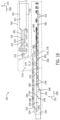
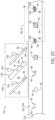
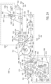
- FIGS. 17 and 18 portions of an exemplary manufacturing line 300 for manufacturing multi-piece closed-back isolation gowns and associated production flow 301 is illustrated, according to an embodiment of the invention.
- FIG. 17 illustrates the machinery in manufacturing line 300 for performing a method of manufacturing multi-piece closed-back isolation gowns.
- the production flow 301 of FIG. 18 illustrates how webs may be manipulated and combined into multi-piece closed-back isolation gown 210 of FIGS. 14-16 in manufacturing line 300.
- like elements in FIGS. 14-16 are numbered identically to corresponding elements in FIGS. 17 and 18 .
- Manufacturing line 300 includes a torso web piece section 302 that forms torso web piece 212, a shoulder web piece section 304 that forms shoulder web pieces 214, and an isolation gown section 306 that forms multi-piece closed-back isolation gown 210 from torso web piece 212 and shoulder web piece 214.
- manufacturing line 300 performs operations along a machine direction 308, but also performs operations in a cross-machine direction 310 that is perpendicular to machine direction 310.
- at least one continuous torso web 312 including a continuous left side panel edge 314 and a continuous right side panel edge 316 is fed into torso web piece section 302 in machine direction 308.
- Continuous torso web 312 may be fed into torso web piece section 302 via a turnbar infeed process during which continuous torso web 312 is unwound from a roll (not shown) and directed past at least one roller 318.
- Torso web piece section 302 will be in one of two configurations 320, 322hh for processing continuous torso webs 312.
- configuration 320 a single continuous torso web 312 is provided and folded.
- two separate continuous torso webs 312 are provided and bonded together.
- continuous torso web 312 is directed to a folding unit 324.
- Folding unit 324 may include folding boards, plow-style folding components, vacuum conveyors, and/or other known folding technologies and is configured to fold continuous torso web 312 in cross-direction 310 at each of continuous left and right side panel edges 314, 316 such that continuous right side panel edge 316 is folded over continuous left side panel edge 314, as shown in FIG. 18 .
- folding over continuous left side panel edge 314 occurs before folding over continuous right side panel edge 316.
- left side panel edge 314 may be folded over right side panel edge 316.
- continuous folded left and right side edges 326, 328 are formed.
- torso web piece section 302 will receive two continuous torso webs 312a, 312b in machine direction 308. Since configuration 322 utilizes two continuous torso webs 312a, 312b rather than a single continuous torso web 312, continuous torso webs 312a, 312b may be much narrower than continuous torso web 312 such as, for example, approximately half the width of continuous torso web 312. Continuous torso webs 312a is laid over continuous web 312b, and continuous torso webs 312a, 312b pass through a bonding unit or apparatus 330. In FIG.
- bonding unit 330 is shown as an ultrasonic bonding unit 330 including a rotary anvil 332 and an ultrasonic fixed blade horn or sonotrode 334 that cooperate to create side seams (not shown) in continuous torso webs 312a, 312b.
- bonding unit 330 may alternatively include components for creating the side seams via a different bonding technique such as, for example, sonic, thermal, pressure, or adhesive bonding techniques or various other forms of bonding known in the industry.
- bonded continuous torso webs 312a, 312b are referred to as continuous torso web 312.
- torso web piece section 302 includes configuration 320 or configuration 322
- the resulting continuous torso web 312 is directed to a cutting unit or apparatus 336 including a rotary anvil 338 aligned with a rotary knife roll 340 having one or more knives 342.
- Each knife 342 may be positioned within an insert (not shown) on rotary knife roll 340 and arranged to align with a corresponding insert (not shown) inset within rotary anvil 338 during operation of cutting unit 336.
- Cutting unit 336 is configured to cut discrete torso web pieces 212 from continuous torso web 312 at a cut line 338, as shown in FIG. 18 .
- discrete torso web pieces 212 may be processed by a number of optional units or apparatus to fold and/or rearrange discrete torso web pieces 212 for placement onto a continuous shoulder web 344.
- torso web piece section 302 may include an optional re-pitching unit or apparatus 346 configured to create a gap between adjacent discrete torso web pieces 212 in machine direction 308, one or more optional folding units or apparatuses 348 configured fold discrete torso web pieces 212, and/or an optional rotational unit or apparatus 350 configured to rotate discrete torso web pieces 212 by approximately 90 degrees, as shown in FIG. 18 as a non-limiting example.
- Optional folding units 348 may be configured to fold discrete torso web pieces 212 in a variety of ways. As non-limiting examples, optional folding units 348 may be configured to bi-fold, tri-fold, or quad-fold torso web pieces 212. Alternatively, the re-pitching, folding, and rotating of discrete torso web pieces 212 may be performed by a single unit or apparatus, as discussed in more detail below with respect to isolation gown section 306.
- shoulder web piece section 304 operates simultaneously with torso web piece section 302.
- at least one continuous shoulder web 344 is fed into shoulder web piece section 304 of manufacturing line 300 in machine direction 308.
- Continuous shoulder web(s) 344 may be fed into shoulder web piece section 304 via a turnbar infeed process during which continuous shoulder web 344 is unwound from a roll (not shown) and directed past at least one roller 352.
- Shoulder web piece section 304 will be in one of two different configurations 354, 356 for processing continuous shoulder webs 344.
- configuration 354 a single continuous shoulder web 344 is provided and processed.
- two separate front and rear continuous shoulder webs 344a, 344b are provided, processed, and bonded together.
- continuous shoulder web 344 is directed to a slitting unit or apparatus 358 including rotary anvil 338 and rotary knife roll 340 with one or more knives 342.
- Slitting unit 358 is configured to form a slit 360 in continuous shoulder web 344 in order to form a continuous cover strip segment 362.
- continuous cover strip segment 362 is cut later on in isolation gown section 306, continuous cover strip segment 362 will become a plurality of discrete cover strip segments 274, as shown in FIGS. 14-16 .
- Continuous cover strip segment 362 is then directed away from continuous shoulder web 344 via one or more rollers 364.
- continuous cover strip segment 362 may be supplied as a separate web or cut from web other than continuous shoulder web 344.
- continuous shoulder web 344 may be narrower.
- continuous shoulder web 344 is directed to a die and/or perforation unit or apparatus 366 including rotary anvil 338 and rotary knife roll 340 with one or more knives 342.
- Die and/or perforation unit 366 is configured to cut neck openings 244 in continuous shoulder web 344 and may optionally cut neck perforation line(s) 246 and thumb slits 248 in continuous shoulder web 344, as shown in FIG. 18 .
- continuous shoulder web 344 enters a folding unit 368, which may include folding boards, plow-style folding components, vacuum conveyors, and/or other known folding technologies.
- a folding unit 368 may include folding boards, plow-style folding components, vacuum conveyors, and/or other known folding technologies.
- the fold in continuous shoulder web 344 is performed to define front and rear shoulder web panels 238, 240 shown mostly clearly in FIG. 15 with folded top edge 242.
- the fold created by folding unit 368 is made slightly off-center in in order to create area 268 uncovered by rear shoulder web 240.
- bonding unit 370 is shown as an ultrasonic bonding unit 370 including rotary anvil 332 and sonotrode 334 that cooperate to create underarm seams in continuous shoulder web 344.
- the underarm seams may be, for example, underarm seams 258 of shoulder web piece 214 of FIGS. 14-16 .
- bonding unit 370 may alternatively include components for creating the underarm seams via a different bonding technique such as, for example, sonic, thermal, pressure, or adhesive bonding techniques or various other forms of bonding known in the industry.
- shoulder web piece section 304 will receive front and rear continuous shoulder webs 344a, 344b that are approximately half as wide as continuous shoulder web 344 in configuration 354 (not counting continuous cover strip segment 362).
- front and rear continuous shoulder webs 344a, 344b will pass through separate die and/or perforation units 366a, 366b, respectively.
- Die and/or perforation unit 366a is configured to create neck openings 244 and/or optional thumb slits 248 in front continuous shoulder web 344a.
- Die and/or perforation unit 366b is configured to create neck openings 244 and/or optional perforation line 246 in rear continuous shoulder web 344b.
- Rear continuous shoulder web 344b also passes through slitting unit 358 to form a slit 360 in rear continuous shoulder web 344b and create continuous cover strip segment 362.
- Continuous cover strip segment 362 is then directed away from rear continuous shoulder web 344b via one or more rollers 364. While FIG. 17 illustrates slitting unit 358 before die and/or perforation unit 366b, they may be reversed in various embodiments.
- continuous cover strip segment 362 may be supplied as a separate web or cut from a web other than rear continuous shoulder web 344b. If continuous cover strip segment 362 is not cut from rear continuous shoulder web 344b, rear continuous shoulder web 344b may be narrower.
- bonding unit 372 is shown in FIG. 17 as including rotary anvil 332 and sonotrode 334 for performing ultrasonic bonding, but may include equipment for performing another bonding technique such as, for example, sonic, thermal, pressure, or adhesive bonding.
- bonding unit 372 in addition to creating underarm seams in continuous shoulder webs 344a, 344b, bonding unit 372 also creates a top seam (not shown) adjacent to top edges (not shown) of continuous shoulder webs 344a, 344b.
- torso web piece 212 and continuous shoulder web 344 are provided by torso and shoulder web piece sections 302, 304, respectively, to isolation gown section 306.
- Continuous cover strip segment 362 is also directed to isolation gown section 306.
- continuous cover strip segment 362 first passes through a perforation unit 375 including rotary anvil 338 and rotatory knife roll 340 including one or more knives 342.
- perforation unit 375 is configured to create perforation lines 284, 286 shown in FIGS. 14 and 16 .
- Isolation gown section 306 includes a torso web piece transfer unit or apparatus 376 configured to transfer discrete torso web pieces 212 in a rotational direction 378 (counter-clockwise in FIGS. 17 and 18 ) such that front surface 225 of each discrete torso web piece 212 is placed onto adhesive strips 272 on continuous shoulder web 344 for attachment to continuous shoulder web 344.
- Transfer unit 376 may be a separate unit from that of re-pitching unit 346, folding unit 348, and/or rotational unit 350 in the form of a vacuum drum in which a vacuum drawn through holes (not shown) in the vacuum drum carries discrete torso web pieces 212 and transfers them to continuous shoulder web 344.
- transfer unit 376 may be in the form of a unit that takes the place of re-pitching unit 346 and/or rotational unit 348.
- the unit may be in the form of a cam-based system (not shown) in which a plurality of vacuum pucks (not shown) may re-pitch and/or rotate discrete torso web pieces 212 and place them onto continuous shoulder web 344.
- the unit may also be a track-based system (not shown) in which a plurality of vacuum pucks (not shown) on a track re-pitch and/or rotate discrete torso web pieces 212 and place them onto continuous shoulder web 344.
- the vacuum pucks may be controlled individually by separate drive elements on the track and could then be more easily reconfigured electronically as necessary.
- transfer unit 376 is the cam-based or track-based system
- discrete torso web pieces 212 may optionally be folded by folding unit 348 before being carried by transfer unit 376.
- Discrete torso web pieces 212 are folded by folding unit 348 slightly off-center such that bottom edge 218 of each discrete torso web piece 212 is folded toward, but spaced apart from, top edge 216.
- an adhesive applicator 380 applies adhesive strips 276, 278 onto rear surface 223 of discrete torso web pieces 212 adjacent top edge 216 and onto rear shoulder web panel 240 adjacent bottom edge 254.
- continuous cover strip segment 362 is placed over adhesive strips 276, 278 to bond together torso web pieces 12 and rear shoulder web panels 38.
- Continuous isolation gown web 382 is directed to a folding unit or apparatus 384, which may include folding boards, plow-style folding components, vacuum conveyors, and/or other known folding technologies. As shown in FIG. 18 , folding unit 384 may fold continuous isolation gown web 382 by folding discrete torso web pieces 212 over continuous shoulder web 344. However, folding unit 384 may also fold discrete torso web pieces 212 under continuous shoulder web 344 or fold continuous shoulder web 344 over or under discrete torso web pieces 212.
- continuous isolation gown 382 passes through a die unit or apparatus 386 including rotary anvil 338 and rotary knife roll 340 with one or more knives 342.
- Die unit 386 is configured to cut out excess underarm and cover strip material and wrist cutouts 388 from continuous shoulder web 344 in front and rear shoulder web panels 238, 240 and create underarm edges 250, 254 in front and rear shoulder web panels 238, 240, respectively.
- Die unit 386 may also be configured to separate continuous isolation gown web 382 into discrete multi-piece closed-back/tube-style isolation gowns 210 including respective torso web pieces 212 and shoulder web pieces 214 at cut lines 390.
- die unit 386 is positioned downstream from folding unit 384.
- die unit 386 may be positioned upstream of folding unit 384.
- FIG. 18 illustrates isolation gowns 210 with torso web piece 212 and shoulder web pieces 214, as similarly shown in FIGS. 14-16 .
- die unit 386 may create cut lines 390 as perforation lines 390 when it is desired to package continuous isolation gown web 382 in a roll from which an individual may tear discrete isolation gowns 210 as needed.
- multi-stage folding unit 392 may include three tuckers (not shown) that perform a tri-fold operation on each isolation gown 210 to make them ready for packaging, as shown in FIG. 18 . While a tri-fold configuration is described herein, it is contemplated that multi-stage folding unit 392 may be configured to create any number of folds in isolation gowns 210 to create the desired package shape.
- multi-stage folding unit 392 may instead by a rewinder for rolling up continuous isolation gown web 382 for packaging in an isolation gown web dispenser (not shown) from which discrete isolation gowns 210 may be torn, as described above.
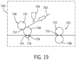
- FIG. 19 is a schematic view of a stretch patch unit or apparatus 700 that may be incorporated into shoulder web piece section 110 of manufacturing line 106 of FIG. 12 between die unit 168 or die units 168a/168b and adhesive applicator 172 or into shoulder web piece section 304 of manufacturing line 300 of FIG. 17 between die unit 366 and folding unit 368 and used to apply neck stretch patches 97 of FIGS. 7-10 , wrist stretch patches 99 of FIGS. 7-9 , and/or wrist stretch patches 109 of FIGS. 10 and 11 when forming shoulder web piece 89 of FIG. 7 , shoulder web piece 91 of FIG. 8 , or shoulder web piece 107 of FIG. 10 .
- FIG. 19 illustrates that at least one continuous stretch patch web 702 may be fed into stretch patch unit 700. This may be done via a turnbar infeed process during which each continuous stretch patch web 702 is unwound from a roll (not shown).
- the number of continuous stretch patch webs 702 supplied to stretch patch unit 700 depends, at least in part, on whether different size stretch patches are necessary to create shoulder web pieces 89, 91, or 107.
- Each continuous stretch web 702 is passed by an adhesive applicator 704 that applies adhesive to continuous stretch web 702. Thereafter, each continuous stretch web 702 is directed to a slip cut unit or apparatus 706 for the creation of stretch patches such as, for example, neck stretch patches 97, wrist stretch patches 99, and/or wrist stretch patches 109.
- Slip cut unit 706 includes of a rotary vacuum anvil 708 and rotary knife roll 710 including one or more knives 712.
- Continuous stretch patch web 702 is fed at a relatively low speed along rotary vacuum anvil 708, which is moving at a relatively higher surface speed and upon which continuous stretch patch web 702 is allowed to "slip.”
- Each knife 712 which is preferably moving at a surface velocity similar to that of rotary vacuum anvil 708, cuts off a segment of continuous stretch patch web 702 against rotary vacuum anvil 708 to create discrete stretch patches (not shown in FIG. 19 ), which, as stated above, may correspond to neck stretch patches 97, wrist stretch patches 99, and/or wrist stretch patches 109.
- each discrete stretch patch is held by a vacuum drawn through holes (not shown in FIG.
- rotary vacuum anvil 708 in rotary vacuum anvil 708 as it is carried at the speed of rotary vacuum anvil 708 downstream to a transfer point 714 where it is transferred onto continuous shoulder web 155 with the adhesive from adhesive applicator 704 contacting continuous shoulder web 155.
- a roller 714 is positioned across from rotary vacuum anvil 708 such that continuous shoulder web 155 with the discrete stretch patches thereon passes through a nip 718 between rotary vacuum anvil 708 and roller 714 in order to press the stretch patches onto continuous shoulder web 155.
- continuous shoulder web 155 passes through one or more die units or apparatuses 720 including rotary anvil 708 and rotary knife roll 710 with one or more knives 712.
- the configuration of knives 712 on rotary knife roll 710 of die unit(s) 720 is designed to cut neck and/or wrist openings in the stretch patches.
- die unit(s) 720 may be configured to cut neck openings 101 in neck stretch patch 97 of FIGS. 7-11 and/or wrist openings 103 in wrist stretch patches 99 of FIGS. 7-9 .
- stretch patches 97, 99, and 109 may be applied to continuous shoulder web 155 by slip cut unit 706 and cut by die unit(s) 720 in stretch patch unit 700 will be described below with respect to FIGS. 20 and 21 .
- Stretch patch unit 700 may be used to place neck stretch patches 97 and wrist stretch patches 99 on continuous shoulder web 155 of FIGS. 12 and 13 or continuous shoulder web 344 of FIGS. 17 and 18 for creating shoulder web pieces 89, 91 shown in FIGS. 7-9 . While not depicted in the simplified view shown in FIG. 20 , it will be understood that stretch patch unit 700 includes slip cut units 706 and die units 720 shown in stretch patch unit 700 of FIG. 19 as necessary to perform stretch patch operations.
- two continuous wrist stretch patch webs 724 and one continuous neck stretch patch web 726 are fed into stretch patch unit 700, and adhesive applicators 704 apply adhesive to webs 724, 726.
- adhesive applicators 704 apply adhesive to webs 724, 726.
- separate slip cut units 706 cut discrete wrist stretch patches 99 and discrete neck stretch patches 97 from continuous wrist and neck stretch patch webs 724, 726, respectively, and place them over wrist openings 93, 95 and neck opening 44, respectively.
- one or more die units 720 cut wrist openings 103 and neck openings 101 in wrist stretch patches 99 and neck stretch patches 97, respectively.
- continuous shoulder web 155 will continue on to isolation gown section 112 of FIG. 12
- continuous shoulder web 344 will continue on to isolation gown section 306 of FIG. 17 .
- stretch patch unit 700 is configured to place neck stretch patches 97 and wrist stretch patches 109 on continuous shoulder web 155 of FIGS. 12 and 13 or continuous shoulder web 344 of FIGS. 17 and 18 for creating shoulder web piece 107 shown in FIG. 10 . While not depicted in the simplified view shown in FIG. 21 , it will be understood that stretch patch unit 700 includes slip cut units 706 and die units 720 shown in stretch patch unit 700 of FIG. 19 as necessary to perform stretch patch operations.
- stretch patch unit 700 utilizes a single continuous stretch patch web 728 due to the fact that neck stretch patches 97 and wrist stretch patches 109 have the same length 113, as shown in FIG. 11 .
- Continuous stretch patch web 728 passes under adhesive applicator 704, which applies adhesive thereto.
- slip cut unit 706 cuts neck stretch patches 97 and discrete wrist stretch patches 109 from continuous stretch patch web 728.
- Each discrete neck stretch patch 97 is placed over one neck opening 44 and every discrete wrist stretch patch 109 is placed over a wrist opening 93.
- one or more die units 720 cut neck opening 101 in neck stretch patches 97 inside of neck opening 44.
- a given wrist stretch patch 109 is divided in half downstream in isolation gown section 112 by die unit 192 and thus forms the right and left wrist portions of two adjacent gowns 105 ( FIG. 10 ).
- continuous shoulder web 155 will continue on to folding and bonding units 184, 186 of isolation gown section 112 shown in FIG. 12
- continuous shoulder web 344 will continue on to folding and bonding units 368, 370 of shoulder web piece section 304 of FIG. 17 .
- Folding and bonding units 184, 186 will perform the folding and bonding operations described above with respect to FIGS. 12 and 13 to form shoulder web pieces 107 shown in FIG. 10 .
- Folding and bonding units 368, 370 will perform the folding and bonding operations described above with respect to FIGS. 17 and 18 to form shoulder web pieces 107 shown in FIG. 10 .
- FIGS. 22 and 23 rear views of multi-piece closed-back/tube-style isolation gowns 480, 482 are illustrated with alternative tie strap configurations to that of isolation gown 210 of FIGS. 14-16 , according to alternative embodiments of the invention. Since isolation gowns 480, 482 are arranged similarly to isolation gown 210 of FIGS. 14-16 , like elements in isolation gowns 210, 480, 482 are numbered identically to corresponding elements in isolation gowns 410.
- isolation gown 480 includes shoulder web piece 214 shown in FIGS. 14-16 and a folded torso web piece 484 including top edge 416, bottom edge 418, folded left and right side edges 420, 422, and overlapping left and right side panel edges 424, 426.
- Torso web piece 484 further includes two tie straps 486, 488. Tie strap 486 is positioned adjacent right side panel edge 426, and tie strap 488 is positioned adjacent tie strap 484.
- torso web piece 484 may be formed from a wider torso web panel than torso web piece 212 of gown 210 ( FIG. 14 ).
- tie straps 486, 488 will remain integrated with torso web piece 484 near top edge 416.
- Tie straps 486, 488 may be tied around a wearer of isolation gown 480 in order to keep isolation gown 480 close to the wearer and further prevent contact with possibly unsafe substances.
- Isolation gown 480 further includes a cover strip segment 495, which may be formed of the same types of material as torso and shoulder web pieces 484, 214.
- Cover strip segment 495 includes upper and lower adhesive strips 276, 278 positioned thereon.
- Cover strip segment 495 is positioned over rear shoulder web panel 240 and rear surface 497 of torso web piece 484 such that upper adhesive strip 276 bonds cover strip segment 495 to rear shoulder web panel 240 and lower adhesive strip 278 bonds cover strip segment 495 to rear surface 497 of torso web piece 484.
- cover strip segment 495 is used to couple together rear shoulder web panel 240 of shoulder web piece 214 and rear surface 497 of torso web piece 484.
- isolation gown 482 includes shoulder web piece 214 shown in FIGS. 14-16 and a folded torso web piece 496 including top edge 416, bottom edge 418, folded left and right side edges 420, 422, and overlapping left and right side panel edges 424, 426.
- Torso web piece 496 also includes two tie straps 498, 500. Tie strap 498 is positioned adjacent right side panel edge 426, and tie strap 500 is positioned adjacent left side panel edge 424 inside of torso web piece 496.
- right side panel edge 426 is folded over left side panel edge 424 by overlapping distance 490 in a similar manner to that of FIG. 22 .
- torso web piece 484 may be formed from a torso web panel with a substantially similar length to that of torso web piece 484 of FIG. 22 .
- tie strap 498 When in use, tie strap 498 will be separated from torso web piece 496 along a perforation line 502, but will remain integrated with torso web piece 496 adjacent top edge 416.
- Tie strap 500 on the other hand, will be completely separated from torso web piece 496 along a perforation line 504. Thereafter, right side panel edge 424 of torso web piece 496 will be where perforation line 504 was before the separation of tie strap 500.
- tie straps 498, 500 may be tied around a wearer of isolation gown 482 in order to keep isolation gown 482 close to the wearer and further prevent contact with possibly unsafe substances.
- Isolation gown 482 further includes a cover strip segment 495 similar to that described above with respect to FIG. 22 .
- FIGS. 24 and 25 portions of an exemplary manufacturing line 506 for manufacturing multi-piece closed-back isolation gowns is illustrated, according to an embodiment of the invention.
- FIG. 24 illustrates the machinery in manufacturing line 506 for performing a method of manufacturing multi-piece closed-back isolation gowns such as, for example, isolation gowns 480 and 482 of FIGS. 22 and 23 .
- FIG. 25 illustrates how webs may be manipulated and combined into multi-piece closed-back isolation gown 480 and 282 of FIGS. 22 and 23 in manufacturing line 506. As such, like elements in FIGS. 22 and 23 are numbered identically to corresponding elements in FIGS. 24 and 25 .
- Manufacturing line 506 includes a torso web piece section 508 that forms one of torso web pieces 484, 496, a shoulder web piece section 510 that forms shoulder web pieces 214, and an isolation gown section 512 that forms multi-piece closed-back isolation gown 480, 482 from torso web pieces 484, 496 and shoulder web piece 214.
- manufacturing line 506 performs operations along a machine direction 514, but also performs operations in a cross-machine direction 516 that is perpendicular to machine direction 514.
- at least one continuous torso web 518 including a continuous left side panel edge 519 and a continuous right side panel edge 521 is fed into torso web piece section 508 in machine direction 514.
- Continuous torso web 518 may be fed into torso web piece section 508 via a turnbar infeed process during which continuous torso web 518 is unwound from a roll (not shown) and directed past at least one roller 520.
- Torso web piece section 508 will be in one of two configurations 523, 525 for processing continuous torso webs 518.
- configuration 523 a single continuous torso web 518 is provided and folded.
- two separate continuous torso webs 518 are provided and bonded together.
- continuous torso web 518 may pass through an optional perforation unit or apparatus 528 including a rotary anvil 530 aligned with a rotary knife roll 532 having one or more knives 534.
- Each knife 534 may be positioned within an insert (not shown) on rotary knife roll 532 and arranged to align with a corresponding insert (not shown) inset within rotary anvil 530 during operation of perforation unit 528.
- Perforation unit 528 may be included in order to cut one or more perforation lines 536 in continuous torso web 518 in order to define one or more integral continuous tie strap webs 538.
- perforation lines 536 may become perforation lines 492, 494 in FIG. 22 , or perforation lines 502, 504 in FIG. 23 in order to define tie straps 486, 488 in FIG. 22 , or tie straps 498, 500 in FIG. 23 .
- continuous torso web 518 is directed to a folding unit 540.
- Folding unit 540 may include folding boards, plow-style folding components, vacuum conveyors, and/or other known folding technologies and is configured to fold continuous torso web 518 in cross-direction 516 at each of continuous left and right side panel edges 519, 521 such that continuous right side panel edge 521 is folded over continuous left side panel edge 519, as shown in FIG. 25 .
- folding over continuous left side panel edge 519 must occur before folding over continuous right side panel edge 521.
- left side panel edge 519 may be folded over right side panel edge 521.
- continuous folded left and right side edges 542, 544 are formed.
- torso web piece section 508 will receive two continuous torso webs 518a, 518b in machine direction 514. Since configuration 525 utilizes two continuous torso webs 518a, 518b rather than a single continuous torso web 518, continuous torso webs 518a, 518b may be much narrower than continuous torso web 518 such as, for example, approximately half the width of continuous torso web 518. Continuous torso webs 518a is laid over continuous web 518b, and continuous torso webs 518a, 518b pass through a bonding unit or apparatus 546. In FIG.
- bonding unit 546 is shown as an ultrasonic bonding unit 546 including a rotary anvil 548 and an ultrasonic fixed blade horn or sonotrode 550 that cooperate to create side seams (not shown) in continuous torso webs 518a, 518b.
- bonding unit 546 may alternatively include components for creating the side seams via a different bonding technique such as, for example, sonic, thermal, pressure, or adhesive bonding techniques or various other forms of bonding known in the industry.
- bonded continuous torso webs 518a, 518b are referred to as continuous torso web 518.
- torso web piece section 508 includes configuration 523 or configuration 525
- the resulting continuous torso web 518 passes through a cutting unit or apparatus 554 for cutting discrete torso web pieces from continuous torso web 518 at a cut line 553, as shown in FIG. 25 .
- the discrete torso web pieces may also be in the form of torso web piece 484 of FIG. 22 of torso web piece 496 of FIG. 23 .
- Cutting unit 554 is shown in FIG. 24 with the same components as perforation unit 528 including rotary anvil 530 aligned with rotary knife roll 532 having one or more knives 534.
- each knife 534 on rotary knife roll 532 is configured to completely separate discrete torso web pieces 484, 496 rather than create perforation lines.
- torso web piece section 508 may include an optional re-pitching unit or apparatus 556 configured to create a gap between adjacent discrete torso web pieces 484, 496 in machine direction 514, an optional folding unit or apparatus 558 configured to fold discrete torso web pieces 484, 496, and/or an optional rotational unit or apparatus 560 configured to rotate discrete torso web pieces 484, 496 by approximately 90 degrees, as shown in FIG. 25 as a non-limiting example.
- Optional folding units 558 may be configured to fold discrete torso web pieces 484, 496 in a variety of ways. As non-limiting examples, optional folding units 558 may be configured to bi-fold, tri-fold, or quad-fold torso web pieces 484, 496. Alternatively, the re-pitching, folding, and rotating of discrete torso web pieces 484, 496 may be performed by a single unit or apparatus, as discussed in more detail below with respect to isolation gown section 512.
- shoulder web piece section 510 operates simultaneously with torso web piece section 508.
- at least one continuous shoulder web 555 is fed into shoulder web piece section 510 of manufacturing line 506 in machine direction 514.
- Continuous shoulder web(s) 555 may be fed into shoulder web piece section 510 via a turnbar infeed process during which continuous shoulder web 555 is unwound from a roll (not shown) and directed past at least one roller 562.
- Shoulder web piece section 510 will be in one of two different configurations 564, 566 for processing continuous shoulder webs 155.
- configuration 564 a single continuous shoulder web 555 is provided and processed.
- two separate front and rear continuous shoulder webs 555a, 555b are provided, processed, and bonded together.
- continuous shoulder web 555 is directed to a slitting unit or apparatus 568 including rotary anvil 530 and rotary knife roll 532 with one or more knives 534.
- Slitting unit 568 is configured to form a slit 570 in continuous shoulder web 555 in order to form a continuous cover strip segment 572.
- continuous cover strip segment 572 is cut later on in isolation gown section 512, continuous cover strip segment 572 will become a plurality of discrete cover strip segments 495, as shown in FIGS. 22 and 23 .
- Continuous cover strip segment 572 is then directed away from continuous shoulder web 555 via one or more rollers 574.
- continuous cover strip segment 572 may be supplied as a separate web or cut from web other than continuous shoulder web 555. If continuous cover strip segment 572 is not cut from continuous shoulder web 555, continuous shoulder web 555 may be narrower. Regardless, an optional perforation unit 575 may be used to create one or more perforation lines in continuous cover strip segment 572. Meanwhile, continuous shoulder web 555 is directed to a die and/or perforation unit or apparatus 576 including rotary anvil 530 and rotary knife roll 532 with one or more knives 534. Die and/or perforation unit 576 is configured to cut neck openings 244 in continuous shoulder web 555 and may optionally cut perforation line 446 and thumb slits 248 in continuous shoulder web 555, as shown in FIG. 25 .
- continuous shoulder web 555 enters a folding unit 578, which may include folding boards, plow-style folding components, vacuum conveyors, and/or other known folding technologies.
- Continuous shoulder web 555 is folded in cross-machine direction 516 to define folded top edge 242 shown in FIGS. 22 and 23 .
- the fold created by folding unit 578 is made slightly off-center in in order to create area 268 uncovered by rear shoulder web 240.
- bonding unit 580 is shown as an ultrasonic bonding unit 580 including rotary anvil 548 and sonotrode 550 that cooperate to create underarm seams in continuous shoulder web 555.
- bonding unit 580 may alternatively include components for creating the underarm seams via a different bonding technique such as, for example, sonic, thermal, pressure, or adhesive bonding techniques or various other forms of bonding known in the industry.
- the underarm seams may be, for example, underarm seams 258 of shoulder web piece 214 of FIGS. 22 and 23 .
- shoulder web piece section 510 will receive front and rear continuous shoulder webs 555a, 555b that are approximately half as wide as continuous shoulder web 555 in configuration 564 (not counting continuous cover strip segment 572).
- front and rear continuous shoulder webs 555a, 555b will pass through separate die and/or perforation units 576a, 576b, respectively.
- Die and/or perforation unit 576a is configured to create neck openings 244 and/or optional thumb slits 248 in front continuous shoulder web 555a.
- Die and/or perforation unit 576b is configured to create neck openings 244 and/or optional perforation line 246 in rear continuous shoulder web 555b.
- Rear continuous shoulder web 555b also passes through slitting unit 568 to form a slit 570 in rear continuous shoulder web 555b and create continuous cover strip segment 572.
- Continuous cover strip segment 572 is then directed away from rear continuous shoulder web 555b via one or more rollers 574. While FIG. 24 illustrates slitting unit 568 before die and/or perforation unit 576b, they may be reversed in various embodiments.
- continuous cover strip segment 572 may be supplied as a separate web or cut from a web other than rear continuous shoulder web 555b. If continuous cover strip segment 572 is not cut from rear continuous shoulder web 555b, rear continuous shoulder web 555b may be narrower.
- bonding unit 582 is shown in FIG. 24 as including rotary anvil 548 and sonotrode 550 for performing ultrasonic bonding, but may include equipment for performing another bonding technique such as, for example, sonic, thermal, pressure, or adhesive bonding.
- bonding unit 582 in addition to creating underarm seams in continuous shoulder webs 555a, 555b, bonding unit 582 also creates a top seam (not shown) adjacent to top edges (not shown) of continuous shoulder webs 555a, 555b.
- continuous shoulder web 555 After passing through configuration 564 or configuration 566, continuous shoulder web 555 passes by an adhesive applicator 584, which applies adhesive strip 272 in area 268 of front shoulder web panel 238 uncovered by rear shoulder web panel 240 shown in FIGS. 22 and 23 .
- Isolation gown section 512 includes a torso web piece transfer unit or apparatus 586 configured to transfer discrete torso web pieces 484, 496 in a rotational direction 588 (counter-clockwise in FIGS. 24 and 25 ) such that front surface 425 of each discrete torso web piece 484, 496 is placed onto adhesive strips 272 on continuous shoulder web 555 for attachment to continuous shoulder web 555.
- Transfer unit 586 may be a separate unit from that of re-pitching unit 556, folding unit 558, and/or rotational unit 560 in the form of a vacuum drum in which a vacuum drawn through holes (not shown) in the vacuum drum carries discrete torso web pieces 484, 496 and transfers them to continuous shoulder web 555.
- transfer unit 586 may be in the form of a unit that takes the place of re-pitching unit 556 and/or rotational unit 558.
- the unit may be in the form of a cam-based system (not shown) in which a plurality of vacuum pucks (not shown) may re-pitch and/or rotate discrete torso web pieces 484, 496 and place them onto continuous shoulder web 555.
- the unit may also be a track-based system (not shown) in which a plurality of vacuum pucks (not shown) on a track re-pitch and/or rotate discrete torso web pieces 484, 496 and place them onto continuous shoulder web 555.
- the vacuum pucks may be controlled individually by separate drive elements on the track and could then be more easily reconfigured electronically as necessary.
- transfer unit 586 is the cam-based or track-based system
- discrete torso web pieces 484, 496 may optionally be folded by folding unit 558 before being carried by transfer unit 586.
- Discrete torso web pieces 484, 496 are folded by folding unit 558 slightly off-center such that bottom edge 418 of each discrete torso web piece 484, 496 is folded toward, but spaced apart from, top edge 416.
- an adhesive applicator 590 applies adhesive strips 276, 278 onto rear surface 225 of discrete torso web pieces 484, 496 adjacent top edge 416 and onto rear shoulder web panel 240 adjacent bottom edge 454.
- optional adhesive applicator 591 is provided in place of or in addition to adhesive applicator 590 to apply adhesive strips 276, 278 onto continuous cover strip segment 572.
- continuous cover strip segment 572 is placed over adhesive strips 276, 278 to bond together torso web pieces 484, 496 and rear shoulder web panels 240.
- continuous isolation gown web 592 is directed to a folding unit or apparatus 594, which may include folding boards, plow-style folding components, vacuum conveyors, and/or other known folding technologies. As shown in FIG. 25 , folding unit 594 may fold continuous isolation gown web 592 by folding discrete torso web pieces 484, 496 over continuous shoulder web 555. However, folding unit 594 may also fold discrete torso web pieces 484, 496 under continuous shoulder web 555 or fold continuous shoulder web 555 over or under discrete torso web pieces 484, 496.
- continuous isolation gown web 592 passes through a die unit or apparatus 596 including rotary anvil 530 and rotary knife roll 532 with one or more knives 534.
- continuous isolation gown web 592 may pass through die unit 596 before folding unit 594.
- Die unit 596 is configured to cut out excess underarm and cover strip material and wrist cutouts 598 from continuous shoulder web 555 in front and rear shoulder web panels 238, 240 and create underarm edges 252, 256 in front and rear shoulder web panels 238, 240, respectively.
- Die unit 596 may also be configured to separate continuous isolation gown web 592 into discrete multi-piece closed-back/tube-style isolation gowns 480, 482 including respective torso web pieces 412 and shoulder web pieces 214 at cut lines 600.
- die unit 596 may create cut lines 600 as perforation lines 600 when it is desired to package continuous isolation gown web 592 in a roll from which an individual may tear discrete isolation gowns 480, 482 as needed.
- multi-stage folding unit 602 may include three tuckers (not shown) that perform a tri-fold operation on each isolation gown 480, 482 to make them ready for packaging, as shown in FIG. 25 . While a tri-fold configuration is described herein, it is contemplated that multi-stage folding unit 602 may be configured to create any number of folds in isolation gowns 480, 482 to create the desired package shape.
- multi-stage folding unit 602 may instead by a rewinder for rolling up continuous isolation gown web 592 for packaging in an isolation gown web dispenser (not shown) from which discrete isolation gowns 480, 482 may be torn, as described above.
- embodiments of the invention include an apparatus and method of manufacturing multi-piece closed-back isolation garments having a torso web piece and a shoulder web piece.
- a torso web piece either a single continuous torso web is folded or two continuous torso webs are bonded together.
- front and rear shoulder web panels are formed by either folding one continuous shoulder web and bonding the overlapping shoulder web layers or by bonding two continuous shoulder webs together.
- Discrete torso web pieces are cut from a continuous torso web by a cutting unit.
- a transfer unit transfers the discrete torso web pieces onto the continuous shoulder web such that top edges of the discrete torso web pieces overlap a bottom edge of the front shoulder web panels of the continuous shoulder web with an adhesive strip.
- the continuous shoulder web is folded over the discrete torso web pieces and bonded with adhesive or a continuous cover strip segment is applied to couple the discrete torso web pieces and continuous shoulder web to form a continuous multi-piece closed-back isolation garment web which may be would into a roll or cut to form discrete isolation garments for folding and packaging.
- the manufacturing of the multi-piece closed-back isolation garments can quickly produce the isolation garments without manual input and with only a small amount of scrap material.
- the formation of the torso web pieces does not result in any scrap material, and the formation of the shoulder web pieces results in only minimal scrap material from cutting neck and wrist openings and excess underarm material.
- an apparatus for manufacturing multi-piece closed-back isolation garments includes a die unit configured to cut neck openings in a continuous shoulder web having a first edge and a second edge opposite the first edge, a first adhesive applicator configured to apply a plurality of first adhesive strips on the continuous shoulder web adjacent to the first edge of the continuous shoulder web, and a transfer unit configured to transfer torso web pieces having a substantially tubular shape onto each first adhesive strip such that a first edge of the torso web piece is overlapping the first edge of the continuous shoulder web.
- the apparatus further includes a second adhesive applicator configured to apply a plurality of second adhesive strips on each torso web piece adjacent to the first edge of each torso web piece, a first folding unit configured to fold the continuous shoulder web such that the second edge of the continuous shoulder web overlaps each second adhesive strip to form first shoulder web panels and second shoulder web panels overlapping each other in the continuous shoulder web, and a bonding unit configured to create underarm seams between first shoulder web panels and second shoulder web panels overlapping each other in the continuous shoulder web to form shoulder web pieces.
- a second adhesive applicator configured to apply a plurality of second adhesive strips on each torso web piece adjacent to the first edge of each torso web piece
- a first folding unit configured to fold the continuous shoulder web such that the second edge of the continuous shoulder web overlaps each second adhesive strip to form first shoulder web panels and second shoulder web panels overlapping each other in the continuous shoulder web
- a bonding unit configured to create underarm seams between first shoulder web panels and second shoulder web panels overlapping each other in the continuous shoulder web to form shoulder
- a method of manufacturing multi-piece closed-back isolation garments includes cutting neck openings in a continuous shoulder web having a first edge and a second edge opposite the first edge with a first die unit, applying a plurality of first adhesive strips on the continuous shoulder web adjacent to the first edge of the continuous shoulder web with an adhesive applicator, and transferring, with a transfer unit, a torso web piece having a substantially tubular shape onto each first adhesive strip such that a first edge of the torso web piece is overlapping the first edge of the continuous shoulder web.
- the method also includes applying a plurality of second adhesive strips on each torso web piece adjacent to the first edge of each torso web piece, folding the continuous shoulder web with a folding unit such that the second edge of the continuous shoulder web overlaps each second adhesive strip to form first shoulder web panels and second shoulder web panels overlapping each other in the continuous shoulder web, and creating underarm seams between the first and second shoulder web panels using a first bonding unit to form shoulder web pieces.
Landscapes
- Engineering & Computer Science (AREA)
- Textile Engineering (AREA)
- Health & Medical Sciences (AREA)
- General Health & Medical Sciences (AREA)
- Physical Education & Sports Medicine (AREA)
- Professional, Industrial, Or Sporting Protective Garments (AREA)
Claims (15)
- Appareil destiné à fabriquer des vêtements d'isolation fermés dans le dos à pièces multiples, l'appareil comprenant :une unité de matrice (168) configurée pour découper des ouvertures de cou dans une bande d'épaule continue (155) ayant un premier bord et un second bord opposé au premier bord ;l'appareil étant caractérisé en ce qu'il comprend en outre :un premier applicateur d'adhésif (172) configuré pour appliquer une pluralité de premières bandes adhésives (174) sur la bande d'épaule continue de manière adjacente au premier bord de la bande d'épaule continue ;une unité de transfert (176) configurée pour transférer des pièces de bande de torse (84) ayant une forme sensiblement tubulaire sur chaque première bande adhésive de telle sorte qu'un premier bord de la pièce de bande de torse chevauche le premier bord de la bande d'épaule continue ;un second applicateur d'adhésif (180) configuré pour appliquer une pluralité de secondes bandes adhésives (182) sur chaque pièce de bande de torse de manière adjacente au premier bord de chaque pièce de bande de torse ;une première unité de pliage (184) configurée pour plier la bande d'épaule continue de telle sorte que le second bord de la bande d'épaule continue chevauche chaque seconde bande adhésive afin de former des premiers panneaux d'épaule et des seconds panneaux d'épaule se chevauchant les uns les autres dans la bande d'épaule continue ; etune unité de collage (186) configurée pour créer des coutures d'aisselles (58) entre des premiers panneaux d'épaule et des seconds panneaux d'épaule se chevauchant les uns les autres dans la bande d'épaule continue afin de former des pièces de bande d'épaule.
- Appareil selon la revendication 1, comprenant en outre :une seconde unité de pliage (140) configurée pour plier une bande de torse continue ayant un premier bord et un second bord opposé au premier bord de telle sorte que les premier et second bords de la bande de torse continue se chevauchent l'un l'autre ; etune unité de découpe (154) configurée pour découper les pièces de bande de torse à partir de la bande de torse continue pliée.
- Appareil selon la revendication 2, comprenant en outre une unité de perforation (128) configurée pour créer au moins une ligne de perforation (92) dans la bande de torse continue afin de définir au moins une sangle d'attache continue intégrée avant que l'unité de pliage ne plie la bande de torse continue de telle sorte que, après que l'unité de découpe ait découpé les pièces de bande de torse à partir de la bande de torse continue pliée, chaque pièce de bande de torse comprend une sangle d'attache intégrée.
- Appareil selon la revendication 1, comprenant en outre une unité de renfort élastique (700) comprenant :au moins un applicateur d'adhésif (704) configuré pour appliquer un adhésif sur au moins une bande de renfort élastique continue ;au moins une unité de découpe par glissement (706) comprenant une enclume à vide (708) et un cylindre à lames (710), l'au moins une unité de découpe par glissement étant configurée pour :recevoir la bande de renfort élastique continue avec l'adhésif appliqué sur l'enclume à vide ;découper la bande de renfort élastique continue en renforts élastiques discrets sur l'enclume à vide avec le cylindre à lames ; etappliquer les renforts élastiques discrets (97) sur les ouvertures de cou sur la bande d'épaule continue avec l'enclume à vide ; etau moins une unité de matrice (720) configurée pour découper des ouvertures dans les renforts élastiques discrets à l'intérieur des ouvertures de cou sur la bande d'épaule continue.
- Appareil selon la revendication 1, dans lequel l'unité de transfert est configurée pour replacer les pièces de bande de torse, tourner les pièces de bande de torse, ou replacer et tourner les pièces de bande de torse tout en transférant les pièces de bande de torse.
- Appareil selon la revendication 1, comprenant en outre une unité de découpe (192) configurée pour découper des vêtements d'isolation fermés dans le dos à pièces multiples discrètes à partir de la bande de vêtements d'isolation continue.
- Appareil selon la revendication 1, comprenant en outre une seconde unité de pliage (198) configurée pour plier en deux, en trois ou en quatre chaque pièce de bande de torse avant qu'elle n'atteigne l'unité de transfert.
- Appareil selon la revendication 1, dans lequel l'unité de matrice est en outre configurée pour découper des lignes de perforation (46) dans la bande d'épaule continue, chaque ligne de perforation s'étendant à partir d'une des ouvertures de cou vers le second bord de la seconde bande d'épaule continue.
- Procédé destiné à fabriquer des vêtements d'isolation fermés dans le dos à pièces multiples avec un appareil selon l'une quelconque des revendications précédentes, le procédé comprenant :découper des ouvertures de cou (44) dans une bande d'épaule continue (155) ayant un premier bord et un second bord opposé au premier bord avec une première unité de matrice ;appliquer une pluralité de premières bandes adhésives (174) sur la bande d'épaule continue de manière adjacente au premier bord de la bande d'épaule continue avec un applicateur d'adhésif (172) ;transférer, avec une unité de transfert (176), une pièce de bande de torse (84) ayant une forme sensiblement tubulaire sur chaque première bande adhésive de telle sorte qu'un premier bord de la pièce de bande de torse chevauche le premier bord de la bande d'épaule continue ;appliquer une pluralité de secondes bandes adhésives (182) sur chaque pièce de bande de torse de manière adjacente au premier bord de chaque pièce de bande de torse ;plier la bande d'épaule continue avec une unité de pliage (184) de telle sorte que le second bord de la bande d'épaule continue chevauche chaque seconde bande adhésive afin de former des premiers panneaux d'épaule et des seconds panneaux d'épaule se chevauchant les uns les autres dans la bande d'épaule continue ; etcréer des coutures d'aisselles (58) entre les premier et second panneaux d'épaule à l'aide d'une première unité de collage (186) afin de former des pièces de bande d'épaule.
- Procédé selon la revendication 9, comprenant en outre le fait de découper la bande d'épaule continue en pièces de bande d'épaule discrètes avec une unité de découpe (192) afin de former des vêtements d'isolation fermés dans le dos à pièces multiples comprenant chacun une des pièces de bande d'épaule et une des pièces de bande de torse.
- Procédé selon la revendication 9, comprenant en outre la formation de chaque pièce de bande de torse par le fait de :plier, avec une unité de pliage (140), une bande de torse continue ayant un premier bord et un second bord opposé au premier bord de telle sorte que les premier et second bords de la bande de torse continue se chevauchent l'un l'autre ; etdécouper, avec une unité de découpe (154), les pièces de bande de torse à partir de la bande de torse continue pliée (118).
- Procédé selon la revendication 11, dans lequel la formation de chaque pièce de bande de torse comprend en outre le fait de découper au moins une ligne de perforation (92) dans la bande de torse continue afin de définir au moins une sangle d'attache continue intégrée avec une unité de perforation avant le pliage de la bande de torse continue ; et
dans lequel, lors de la découpe des pièces de bande de torse discrètes à partir de la bande de torse continue pliée, chaque pièce de bande de torse discrète inclut au moins une sangle d'attache intégrée. - Procédé selon la revendication 11, dans lequel la formation de chaque pièce de bande de torse comprend en outre :inciser au moins une sangle d'attache continue à partir de la bande de torse continue avec une unité d'incision (122) avant de plier la bande de torse continue ; etaprès le pliage de la bande de torse continue, réattacher la sangle d'attache continue à la bande de torse continue avec l'adhésif ;dans lequel, lors de la découpe des pièces de bande de torse discrètes à partir de la bande de torse continue pliée, chaque pièce de bande de torse discrète inclut au moins une sangle d'attache.
- Procédé selon la revendication 9 comprenant en outre :appliquer un renfort élastique de cou (97) sur chaque ouverture de cou dans la bande d'épaule continue avec une première unité de découpe par glissement ; etdécouper une ouverture dans chaque renfort élastique de cou avec une deuxième unité de matrice (720).
- Procédé selon la revendication 14, comprenant en outre :découper des ouvertures de poignet (93, 95) dans la bande d'épaule continue à l'aide de la première unité de matrice ;appliquer un renfort élastique de poignet (99) sur chaque ouverture de poignet dans la bande d'épaule continue à l'aide de la première unité de découpe par glissement ou d'une seconde unité de découpe par glissement ; etdécouper une ouverture (103) dans chaque renfort élastique de poignet à l'aide d'une troisième unité de matrice (103).
Applications Claiming Priority (2)
| Application Number | Priority Date | Filing Date | Title |
|---|---|---|---|
| US202163202098P | 2021-05-27 | 2021-05-27 | |
| PCT/US2022/030782 WO2022251260A1 (fr) | 2021-05-27 | 2022-05-24 | Appareil et procédé de fabrication de vêtements d'isolation fermés dans le dos à pièces multiples |
Publications (3)
| Publication Number | Publication Date |
|---|---|
| EP4346475A1 EP4346475A1 (fr) | 2024-04-10 |
| EP4346475C0 EP4346475C0 (fr) | 2025-05-07 |
| EP4346475B1 true EP4346475B1 (fr) | 2025-05-07 |
Family
ID=82156396
Family Applications (1)
| Application Number | Title | Priority Date | Filing Date |
|---|---|---|---|
| EP22732762.4A Active EP4346475B1 (fr) | 2021-05-27 | 2022-05-24 | Appareil et procédé de fabrication de vêtements d'isolation fermés dans le dos à pièces multiples |
Country Status (7)
| Country | Link |
|---|---|
| US (1) | US20240285005A1 (fr) |
| EP (1) | EP4346475B1 (fr) |
| CA (1) | CA3217807A1 (fr) |
| ES (1) | ES3030349T3 (fr) |
| MX (1) | MX2023014044A (fr) |
| PL (1) | PL4346475T3 (fr) |
| WO (1) | WO2022251260A1 (fr) |
Families Citing this family (1)
| Publication number | Priority date | Publication date | Assignee | Title |
|---|---|---|---|---|
| WO2022260858A1 (fr) | 2021-06-11 | 2022-12-15 | Curt G. Joa, Inc. | Appareil et procédé de fabrication de vêtements d'isolation à ouverture dans le dos à pièces multiples |
Family Cites Families (6)
| Publication number | Priority date | Publication date | Assignee | Title |
|---|---|---|---|---|
| US3639915A (en) * | 1969-06-20 | 1972-02-08 | Kimberly Clark Co | Disposable garment and method and apparatus for making same |
| BE795062A (fr) * | 1972-02-10 | 1973-05-29 | Mo Och Domsjoe Ab | Vetement a usage limite, ainsi que procede et dispositif pour la fabrication du dit vetement |
| US4837860A (en) * | 1988-04-04 | 1989-06-13 | Roberts Thomas J | Protective garment |
| US5025501A (en) * | 1989-12-22 | 1991-06-25 | Dillon John L | Medical garment and method for manufacturing the same |
| WO2021092606A1 (fr) * | 2019-11-04 | 2021-05-14 | The Procter & Gamble Company | Procédé et appareil de fixation de parties élastiques sous tension à un support en mouvement |
| EP3977882A1 (fr) * | 2020-10-05 | 2022-04-06 | Trioplast Landskrona AB | Production de vêtements jetables |
-
2022
- 2022-05-24 EP EP22732762.4A patent/EP4346475B1/fr active Active
- 2022-05-24 PL PL22732762.4T patent/PL4346475T3/pl unknown
- 2022-05-24 CA CA3217807A patent/CA3217807A1/fr active Pending
- 2022-05-24 MX MX2023014044A patent/MX2023014044A/es unknown
- 2022-05-24 ES ES22732762T patent/ES3030349T3/es active Active
- 2022-05-24 US US18/564,517 patent/US20240285005A1/en active Pending
- 2022-05-24 WO PCT/US2022/030782 patent/WO2022251260A1/fr not_active Ceased
Also Published As
| Publication number | Publication date |
|---|---|
| PL4346475T3 (pl) | 2025-09-08 |
| EP4346475C0 (fr) | 2025-05-07 |
| ES3030349T3 (en) | 2025-06-27 |
| WO2022251260A1 (fr) | 2022-12-01 |
| US20240285005A1 (en) | 2024-08-29 |
| CA3217807A1 (fr) | 2022-12-01 |
| MX2023014044A (es) | 2023-12-12 |
| EP4346475A1 (fr) | 2024-04-10 |
Similar Documents
| Publication | Publication Date | Title |
|---|---|---|
| EP4346476B1 (fr) | Appareil et procédé de fabrication de vêtements d'isolation à ouverture dans le dos à pièces multiples | |
| EP1707168B1 (fr) | Méthode de production d'articles de type pantalons | |
| US3639915A (en) | Disposable garment and method and apparatus for making same | |
| JP6109158B2 (ja) | 使い捨て着用物品の製造方法 | |
| CN103269663B (zh) | 形成用于个人护理制品的具有目标弹性性质的弹性体层压材料的方法 | |
| TW201907982A (zh) | 具展翼之口罩及其製造工序 | |
| CN104783969B (zh) | 用于生产设有侧幅可作为裤子穿的卫生物品的方法和装置 | |
| CN103945806B (zh) | 短裤型穿着用物品的制造方法 | |
| US20130037201A1 (en) | Methods and apparatus for application of nested zero waste ear to traveling web and formation of articles using a dual cut slip unit | |
| TWI405547B (zh) | 敷劑用片包裝體及敷劑用片的包裝方法 | |
| WO2014208638A1 (fr) | Article à porter de type culotte, et son procédé de production | |
| EP4346475B1 (fr) | Appareil et procédé de fabrication de vêtements d'isolation fermés dans le dos à pièces multiples | |
| CN116685228A (zh) | 一次性服装的生产 | |
| EP4346474B1 (fr) | Appareil et procédé de fabrication de vêtements d'isolation fermés dans le dos à pièces multiples | |
| US12610997B2 (en) | Apparatus and method of manufacturing multi-piece closed-back isolation garments | |
| US4523336A (en) | Method for manufacture of sleeved garments outside out | |
| JP4521290B2 (ja) | 着用物品ならびに、その製造方法および製造装置 | |
| EP3138428B1 (fr) | Tablier avec ajustement de l'encolure amelioré | |
| CN116985402A (zh) | 一种超密合口罩生产设备及制造方法 | |
| KR20230049882A (ko) | 의료 가운, 그 제조장치 및 제조방법 | |
| JP2023039203A (ja) | 衣服の製造方法 | |
| EP2813199B1 (fr) | Procédé pour produire un article absorbant avec un panneau latéral en film extensible |
Legal Events
| Date | Code | Title | Description |
|---|---|---|---|
| STAA | Information on the status of an ep patent application or granted ep patent |
Free format text: STATUS: UNKNOWN |
|
| STAA | Information on the status of an ep patent application or granted ep patent |
Free format text: STATUS: THE INTERNATIONAL PUBLICATION HAS BEEN MADE |
|
| PUAI | Public reference made under article 153(3) epc to a published international application that has entered the european phase |
Free format text: ORIGINAL CODE: 0009012 |
|
| STAA | Information on the status of an ep patent application or granted ep patent |
Free format text: STATUS: REQUEST FOR EXAMINATION WAS MADE |
|
| 17P | Request for examination filed |
Effective date: 20231127 |
|
| AK | Designated contracting states |
Kind code of ref document: A1 Designated state(s): AL AT BE BG CH CY CZ DE DK EE ES FI FR GB GR HR HU IE IS IT LI LT LU LV MC MK MT NL NO PL PT RO RS SE SI SK SM TR |
|
| DAV | Request for validation of the european patent (deleted) | ||
| DAX | Request for extension of the european patent (deleted) | ||
| GRAP | Despatch of communication of intention to grant a patent |
Free format text: ORIGINAL CODE: EPIDOSNIGR1 |
|
| STAA | Information on the status of an ep patent application or granted ep patent |
Free format text: STATUS: GRANT OF PATENT IS INTENDED |
|
| INTG | Intention to grant announced |
Effective date: 20241205 |
|
| GRAS | Grant fee paid |
Free format text: ORIGINAL CODE: EPIDOSNIGR3 |
|
| GRAA | (expected) grant |
Free format text: ORIGINAL CODE: 0009210 |
|
| STAA | Information on the status of an ep patent application or granted ep patent |
Free format text: STATUS: THE PATENT HAS BEEN GRANTED |
|
| AK | Designated contracting states |
Kind code of ref document: B1 Designated state(s): AL AT BE BG CH CY CZ DE DK EE ES FI FR GB GR HR HU IE IS IT LI LT LU LV MC MK MT NL NO PL PT RO RS SE SI SK SM TR |
|
| REG | Reference to a national code |
Ref country code: GB Ref legal event code: FG4D |
|
| REG | Reference to a national code |
Ref country code: CH Ref legal event code: EP |
|
| REG | Reference to a national code |
Ref country code: DE Ref legal event code: R096 Ref document number: 602022014364 Country of ref document: DE |
|
| REG | Reference to a national code |
Ref country code: IE Ref legal event code: FG4D |
|
| REG | Reference to a national code |
Ref country code: ES Ref legal event code: FG2A Ref document number: 3030349 Country of ref document: ES Kind code of ref document: T3 Effective date: 20250627 |
|
| U01 | Request for unitary effect filed |
Effective date: 20250526 |
|
| U07 | Unitary effect registered |
Designated state(s): AT BE BG DE DK EE FI FR IT LT LU LV MT NL PT RO SE SI Effective date: 20250603 |
|
| U20 | Renewal fee for the european patent with unitary effect paid |
Year of fee payment: 4 Effective date: 20250602 |
|
| PGFP | Annual fee paid to national office [announced via postgrant information from national office to epo] |
Ref country code: ES Payment date: 20250602 Year of fee payment: 4 |
|
| PG25 | Lapsed in a contracting state [announced via postgrant information from national office to epo] |
Ref country code: GR Free format text: LAPSE BECAUSE OF FAILURE TO SUBMIT A TRANSLATION OF THE DESCRIPTION OR TO PAY THE FEE WITHIN THE PRESCRIBED TIME-LIMIT Effective date: 20250808 Ref country code: NO Free format text: LAPSE BECAUSE OF FAILURE TO SUBMIT A TRANSLATION OF THE DESCRIPTION OR TO PAY THE FEE WITHIN THE PRESCRIBED TIME-LIMIT Effective date: 20250807 |
|
| PGFP | Annual fee paid to national office [announced via postgrant information from national office to epo] |
Ref country code: TR Payment date: 20250723 Year of fee payment: 4 Ref country code: PL Payment date: 20250623 Year of fee payment: 4 |
|
| PG25 | Lapsed in a contracting state [announced via postgrant information from national office to epo] |
Ref country code: HR Free format text: LAPSE BECAUSE OF FAILURE TO SUBMIT A TRANSLATION OF THE DESCRIPTION OR TO PAY THE FEE WITHIN THE PRESCRIBED TIME-LIMIT Effective date: 20250507 |
|
| PG25 | Lapsed in a contracting state [announced via postgrant information from national office to epo] |
Ref country code: RS Free format text: LAPSE BECAUSE OF FAILURE TO SUBMIT A TRANSLATION OF THE DESCRIPTION OR TO PAY THE FEE WITHIN THE PRESCRIBED TIME-LIMIT Effective date: 20250807 |
|
| PG25 | Lapsed in a contracting state [announced via postgrant information from national office to epo] |
Ref country code: IS Free format text: LAPSE BECAUSE OF FAILURE TO SUBMIT A TRANSLATION OF THE DESCRIPTION OR TO PAY THE FEE WITHIN THE PRESCRIBED TIME-LIMIT Effective date: 20250907 |
|
| REG | Reference to a national code |
Ref country code: CH Ref legal event code: H13 Free format text: ST27 STATUS EVENT CODE: U-0-0-H10-H13 (AS PROVIDED BY THE NATIONAL OFFICE) Effective date: 20251223 |
|
| PG25 | Lapsed in a contracting state [announced via postgrant information from national office to epo] |
Ref country code: SM Free format text: LAPSE BECAUSE OF FAILURE TO SUBMIT A TRANSLATION OF THE DESCRIPTION OR TO PAY THE FEE WITHIN THE PRESCRIBED TIME-LIMIT Effective date: 20250507 |
|
| PG25 | Lapsed in a contracting state [announced via postgrant information from national office to epo] |
Ref country code: CH Free format text: LAPSE BECAUSE OF NON-PAYMENT OF DUE FEES Effective date: 20250531 |
|
| PG25 | Lapsed in a contracting state [announced via postgrant information from national office to epo] |
Ref country code: CZ Free format text: LAPSE BECAUSE OF FAILURE TO SUBMIT A TRANSLATION OF THE DESCRIPTION OR TO PAY THE FEE WITHIN THE PRESCRIBED TIME-LIMIT Effective date: 20250507 |
|
| PG25 | Lapsed in a contracting state [announced via postgrant information from national office to epo] |
Ref country code: SK Free format text: LAPSE BECAUSE OF FAILURE TO SUBMIT A TRANSLATION OF THE DESCRIPTION OR TO PAY THE FEE WITHIN THE PRESCRIBED TIME-LIMIT Effective date: 20250507 |
|
| PG25 | Lapsed in a contracting state [announced via postgrant information from national office to epo] |
Ref country code: MC Free format text: LAPSE BECAUSE OF FAILURE TO SUBMIT A TRANSLATION OF THE DESCRIPTION OR TO PAY THE FEE WITHIN THE PRESCRIBED TIME-LIMIT Effective date: 20250507 |
|
| PLBE | No opposition filed within time limit |
Free format text: ORIGINAL CODE: 0009261 |
|
| STAA | Information on the status of an ep patent application or granted ep patent |
Free format text: STATUS: NO OPPOSITION FILED WITHIN TIME LIMIT |
|
| REG | Reference to a national code |
Ref country code: CH Ref legal event code: L10 Free format text: ST27 STATUS EVENT CODE: U-0-0-L10-L00 (AS PROVIDED BY THE NATIONAL OFFICE) Effective date: 20260318 |
|
| PG25 | Lapsed in a contracting state [announced via postgrant information from national office to epo] |
Ref country code: IE Free format text: LAPSE BECAUSE OF NON-PAYMENT OF DUE FEES Effective date: 20250524 |
|
| 26N | No opposition filed |
Effective date: 20260210 |