EP4347175B1 - Étalonnage d'une estimation qualité pour un procédé de coupe laser - Google Patents
Étalonnage d'une estimation qualité pour un procédé de coupe laser Download PDFInfo
- Publication number
- EP4347175B1 EP4347175B1 EP22731166.9A EP22731166A EP4347175B1 EP 4347175 B1 EP4347175 B1 EP 4347175B1 EP 22731166 A EP22731166 A EP 22731166A EP 4347175 B1 EP4347175 B1 EP 4347175B1
- Authority
- EP
- European Patent Office
- Prior art keywords
- quality
- real
- cutting
- calibration
- sensor
- Prior art date
- Legal status (The legal status is an assumption and is not a legal conclusion. Google has not performed a legal analysis and makes no representation as to the accuracy of the status listed.)
- Active
Links
Images



Classifications
-
- B—PERFORMING OPERATIONS; TRANSPORTING
- B23—MACHINE TOOLS; METAL-WORKING NOT OTHERWISE PROVIDED FOR
- B23K—SOLDERING OR UNSOLDERING; WELDING; CLADDING OR PLATING BY SOLDERING OR WELDING; CUTTING BY APPLYING HEAT LOCALLY, e.g. FLAME CUTTING; WORKING BY LASER BEAM
- B23K31/00—Processes relevant to this subclass, specially adapted for particular articles or purposes, but not covered by any single one of main groups B23K1/00 - B23K28/00
- B23K31/12—Processes relevant to this subclass, specially adapted for particular articles or purposes, but not covered by any single one of main groups B23K1/00 - B23K28/00 relating to investigating the properties, e.g. the weldability, of materials
- B23K31/125—Weld quality monitoring
-
- B—PERFORMING OPERATIONS; TRANSPORTING
- B23—MACHINE TOOLS; METAL-WORKING NOT OTHERWISE PROVIDED FOR
- B23K—SOLDERING OR UNSOLDERING; WELDING; CLADDING OR PLATING BY SOLDERING OR WELDING; CUTTING BY APPLYING HEAT LOCALLY, e.g. FLAME CUTTING; WORKING BY LASER BEAM
- B23K26/00—Working by laser beam, e.g. welding, cutting or boring
- B23K26/02—Positioning or observing the workpiece, e.g. with respect to the point of impact; Aligning, aiming or focusing the laser beam
- B23K26/03—Observing, e.g. monitoring, the workpiece
- B23K26/032—Observing, e.g. monitoring, the workpiece using optical means
-
- B—PERFORMING OPERATIONS; TRANSPORTING
- B23—MACHINE TOOLS; METAL-WORKING NOT OTHERWISE PROVIDED FOR
- B23K—SOLDERING OR UNSOLDERING; WELDING; CLADDING OR PLATING BY SOLDERING OR WELDING; CUTTING BY APPLYING HEAT LOCALLY, e.g. FLAME CUTTING; WORKING BY LASER BEAM
- B23K26/00—Working by laser beam, e.g. welding, cutting or boring
- B23K26/36—Removing material
- B23K26/38—Removing material by boring or cutting
-
- B—PERFORMING OPERATIONS; TRANSPORTING
- B23—MACHINE TOOLS; METAL-WORKING NOT OTHERWISE PROVIDED FOR
- B23K—SOLDERING OR UNSOLDERING; WELDING; CLADDING OR PLATING BY SOLDERING OR WELDING; CUTTING BY APPLYING HEAT LOCALLY, e.g. FLAME CUTTING; WORKING BY LASER BEAM
- B23K31/00—Processes relevant to this subclass, specially adapted for particular articles or purposes, but not covered by any single one of main groups B23K1/00 - B23K28/00
- B23K31/006—Processes relevant to this subclass, specially adapted for particular articles or purposes, but not covered by any single one of main groups B23K1/00 - B23K28/00 relating to using of neural networks
-
- G—PHYSICS
- G01—MEASURING; TESTING
- G01D—MEASURING NOT SPECIALLY ADAPTED FOR A SPECIFIC VARIABLE; ARRANGEMENTS FOR MEASURING TWO OR MORE VARIABLES NOT COVERED IN A SINGLE OTHER SUBCLASS; TARIFF METERING APPARATUS; MEASURING OR TESTING NOT OTHERWISE PROVIDED FOR
- G01D18/00—Testing or calibrating apparatus or arrangements provided for in groups G01D1/00 - G01D15/00
Definitions
- Important aspects of a laser cutting machine are its cutting quality, cutting speed and machine autonomy. If the cutting process can be monitored effectively, the machine can be improved in all three essential criteria. Accordingly, monitoring the cutting process has become increasingly important in recent years. Today's machines are increasingly equipped with photodiodes and sometimes even cameras, which enable real-time monitoring of the machining process.
- the subsequent measurement of cutting edges of cut parts has also become established, wherein the focus is now mostly on the cutting quality.
- Imaging devices such as cameras are often used for this purpose.
- the cutting quality can be extracted from the captured images of the cutting edge based on a number of quality parameters such as roughness, presence of burrs or slag adhesion and other quality criteria. This information can also be used to optimally set the cutting parameters for future cutting operations.
- DE102019209088A1 also proposes using mobile phone photos to assess cutting edges.
- US9529343B2 also addresses the presently established prior art. It is proposed therein to collect both sensor data that is generated during cutting and image data of the cutting edge that is recorded after cutting, to combine these and thus jointly derive a determination of the cutting performance and, if necessary, to provide suggestions for improving said cutting performance.
- WO2020069889A1 also proposes something similar.
- a method parameter algorithm is presented, which provides optimised method parameters for the cutting process based on the material and machine parameters as well as the desired cutting edge quality.
- the edge quality achieved can be recorded with a camera and also made available to the algorithm in order to further optimise the method parameters.
- WO2021073946A1 shows that, for example, monitoring conditions can first be defined in a configuration phase, so that, so to speak, first a processing step for setting a monitoring condition takes place, then a processing step with monitoring activated and, via a process signal, again entering a setting step for determining a new monitoring condition.
- EP3159093B1 describes a camera arrangement on the cutting head in order to be able to observe the process coaxially along the processing laser in real time during cutting in order to be able to interrupt the cutting process with an error message or continue it in a modified way (with changed cutting parameters) or to initiate a post-processing of defects.
- estimation methods can be used in order to estimate the quality of a cutting process in advance of the cutting process, for example in order to be able to adapt the cutting parameters if the estimation result outputs a quality that is too low.
- the estimation methods known from the prior art for estimating quality are subject to interference, which makes the estimation result less reliable, which in turn has a disadvantageous effect on the subsequent cutting process and its quality.
- the estimation methods are subject to temporal drifts (shifts) in long-term behaviour, sometimes due to ageing of the sensors and optics, wear and tear, etc.
- Estimation methods in particular have thus proved to be deficient, the data basis of which is static.
- a further disadvantage can be seen in the fact that the quality estimation is not individually adjusted to the respective laser cutting machine, the workpiece to be cut and/or the cutting environment.
- the object of the invention is to improve (online) quality estimation and, in particular, to make it more robust against interference and dynamically changing parameters.
- the quality estimation should be configurable based on the currently cut workpiece material, its alloy and/or surface and/or its thickness.
- the object is achieved by a method for calibrating a real-time estimator according to claim 1, which is intended for quality estimation of a cutting method using a laser cutting machine.
- the method includes the following method steps:
- Calibration here means an adjustment of the estimator, in particular periodically or recurrently according to a preconfigurable scheme, with feedback of the actually measured quality values.
- the calibration therefore does not refer to the cutting process, but only to the real-time estimator.
- Calibration can also be understood as a regulation.
- the quality estimation preferably takes place in real time, i.e. during the cutting process and thus online.
- the quality estimation is carried out, so to speak, parallel to the movement of the laser cutting head over the sheet metal or the material to be cut.
- the quality can also be estimated in a test cut and thus not on parts of the production batch.
- one advantage of the quality estimation proposed here is that the quality estimation is provided without a calibration or test cut and continuously in the ongoing cutting process.
- the quality measurement is carried out offline, i.e. usually after cutting.
- “Quality measurement” here means the calculation of the real and current cutting edge quality on the basis of measured or detected signals, in particular optical signals (e.g. a camera image).
- the real-time estimator is designed to execute an estimation algorithm.
- the estimation algorithm calculates the quality estimation result at least from detected sensor signals of at least one sensor.
- the estimation algorithm is known per se from the prior art. For example, reference is made here to EP2357057A1 , in which a method is described for monitoring the quality of laser machining processes by detecting signals via optical sensors, such as photodiodes. Characteristic parameters are calculated from the signals using image processing methods, and a reference to the standard cutting quality is calculated for the corresponding parameters in order to estimate the quality. Another method is outlined in the work of Santolini, G. et al.: Cut Quality Estimation in Industrial Laser Cutting Machines: A Machine Learning Approach, CVPR 2019 . Sensors and a DNN (deep neural network) are used here to draw conclusions about the cutting quality.
- DNN deep neural network
- the estimation algorithm can also be designed according to the specifications as described in EP20 165 589.1 , the content of which is referred to here.
- the estimation algorithm of the real-time estimator can be designed using machine learning methods.
- the real-time estimator can comprise a model, preferably a convolutional network (CNN) with several hidden layers as network layers, in particular a convolutional layer (CONV), followed by an activation layer (ACT), followed by a pooling layer (POOL).
- CNN convolutional network
- CONV convolutional layer
- ACT activation layer
- POOL pooling layer
- the real-time estimator can preferably also have a time architecture in order to process and extract the information content that is in the temporal dimension of the process signals and thus enable a statement to be made about the signal profile over time.
- a time architecture in order to map the signal sequence in the DNN in this case and thus to be able to learn time-dependent features, so-called gated recurrent units (GRU) or long short-term memory networks (LSTM) can be used in combination with the CNN.
- GRU gated recurrent units
- LSTM long short-term memory networks
- CNN convolutional neural networks
- RNN residual neural networks
- GRU Gated recurrent unit
- LSTM long short-term memory
- the method according to the invention and in particular the calibration method including the calculation of the calibration data set can use a machine learning model. Provision can be made, for example, for the calibration model and/or the real-time estimator to be adapted using an action-reward learning algorithm, in particular using a reinforcement learning algorithm.
- An alternative particularly preferred embodiment is based on the fact that the calibration model and/or the real-time estimator is adapted to new materials (e.g. new alloys or other material thicknesses) by means of a transfer learning method in order to transfer the real-time estimator and/or model trained for a material of type A to a material of type B.
- new materials e.g. new alloys or other material thicknesses
- a transfer learning method in order to transfer the real-time estimator and/or model trained for a material of type A to a material of type B.
- different abstract features can be reused.
- the transfer learning method can also be used to transfer the calculated or learned knowledge to other types of processes, in particular cutting process types such as laser fusion cutting, laser flame cutting, laser-induced plasma cutting, plasma-assisted fusion cutting, or plasma-assisted flame cutting.
- cutting process types such as laser fusion cutting, laser flame cutting, laser-induced plasma cutting, plasma-assisted fusion cutting, or plasma-assisted flame cutting.
- the model can be supported by characteristic values, which are obtained directly from the sensor data using unsupervised learning methods. No quality measurements are required to calculate these supporting parameters. As a result, the essential process variations in the sensor signals or data can be recognised even if there are only a few quality measurements. Methods such as clustering, autoencoder, dimensionality reduction techniques such as k-NN/k-nearest neighbour, PCA/principal component analysis, etc. can be used.
- the sensor data are preferably optical sensor data that are recorded during cutting (online) by a suitable first sensor system, hereinafter referred to as "sensor” (e.g. photodiodes, camera, OCT, acoustic sensors), i.e. during online process monitoring.
- sensor e.g. photodiodes, camera, OCT, acoustic sensors
- This sensor data is transferred to the estimation algorithm as input data.
- the term "sensor” is understood to be a sensor unit and may include multiple separate sensors of the same or different type.
- the sensor data (digital) or sensor signals (analogue) recorded in this way can be combined using a sensor fusion technique.
- the optional input data are material type, thickness, cutting process, laser power, cutting gas pressure, gas type, nozzle type/size, feed, nozzle spacing, focus position.
- the detected sensor data and/or measurement signals are assigned to position identification data (position identifier) in order to be able to uniquely address and identify the data set and to be able to provide a spatial resolution. This is important in order to subsequently carry out the comparison on those data sets that have been acquired at the same position of the part and in particular the cutting edge. This is therefore important in order to be able to match (pair or assign) the measurement and estimation at the same position for the comparison step.
- the first sensor system is implemented as an optical sensor, in particular as a camera arranged coaxially in the cutting head.
- the first sensor system or the sensor can also be an acoustic sensor or a sensor for detecting other signal types, such as a thermal sensor system with a pyrometric camera.
- the first sensor system or the sensor transmits sensor signals.
- the second sensor system is implemented as a measuring device, in particular as an optical measuring device (e.g. as a camera) and can be used to record offline measuring signals at the cutting edge of the workpiece.
- “Offline” here means the sensory detection after the workpiece has been cut or after a partial cutting process, which is interrupted for the purpose of measurement and enables optical detection of the cutting edge.
- the second sensor system or the measuring device can be arranged in a downstream system for the laser cutting machine, such as a sorting system, a transport system and/or a bending system.
- the measuring device can also be accommodated in the laser cutting machine itself, in order to measure a cutting edge, for example and preferably intermittently, for cutting production parts.
- the measuring device can also be designed for the direct measurement of quality signals, as will be explained later (e.g. profilometer).
- the measurement device may be a multi-module device and may comprise a plurality of separate sensors, detectors, measurement modules of the same or a different type.
- the second sensor system or the measuring device delivers measuring signals.
- the output data of the estimation algorithm include information on the cutting quality currently achieved in the cutting process.
- the cutting quality includes the following characteristics (not exhaustive), whereby some characteristics are also referred to as quality defects: Roughness, craters, burrs, slag residue, welding.
- the features are preferably output in quality classes. For example, 3 to 6 quality classes can be output, namely "very good”, “good”, “medium”, “moderate”, “poor”.
- the type and number of classes can be configured in a configuration phase.
- the output data can be categorical. However, it is alternatively or cumulatively possible to specify both the burr height and the roughness with a continuous estimation number between 0 and 1 with numerical values in order to provide a more detailed estimation result.
- a quality class output is currently preferred.
- the estimation algorithm of the quality estimator may supply the direct quantitative characteristics, i.e., for example, the burr height in a unit of measure such as ⁇ m and/or the roughness in a unit of measurement. This simplifies the subsequent digital comparison with the quality measurement.
- the respective quality measurement result is subjected to an additional method step, namely a binning method that classifies the quality measurement results into appropriate classes according to the qualitative characteristics of the estimator. This can simplify the comparison between measurement and estimation for categorical values.
- the steps of the method of loading, providing and comparing are preferably carried out in the order described. It is particularly preferred that the loading and the sensor signal detection with the sensor take place online, i.e. during a productive cutting process or on parts of the production batch, while the provision and detection of the measurement signals, in particular the cutting edge image of the finished cut part, by means of the measuring device in one subsequent time phase and in particular after completion of the cutting process. Alternatively, the detection of the measurement signals can also be integrated into the cutting process, as described above (interruption of the cutting process when the cutting edge is partially exposed).
- the estimation algorithm is based on input data supplied from the sensor, preferably continuously.
- the provision of the quality measurement result is based on other input data supplied by the measurement device.
- the activation of the measuring device can be triggered automatically by an activation signal from the calibration module or by manual intervention.
- the comparison of the estimate with the measurement (both with regard to quality) and/or the calculation of the calibration data set is preferably event-based.
- the comparison and/or the calculation (of the calibration data set) is carried out continuously.
- the comparison/calculation is not always carried out, but only when required, in particular when preconfigured events occur.
- the events can be time-based or situation-based.
- a threshold can be configured. According to the invention, as soon as the comparison shows a deviation above the configured threshold value, the calculation of the calibration data set is triggered instantaneously and the calibration of the real-time estimator is also triggered.
- the calculation is suspended for a specific time phase, namely preferably when the deviations are below the threshold value and thus indicate that the estimation and measurement are compliant up to a likewise preconfigurable tolerance range and no adjustment of the estimator is required is.
- the calculation of the calibration data set can be initialised or triggered by different events, such as the provision of new measured values, the completion of a cutting process, after timed events or after predefined events (if, for example, a certain area of a workpiece sheet is cut or if the deviation exceeds a exceeds threshold or other configurable events). This can be implemented in a trigger component. This saves computing capacity since the comparison is only performed when it is required. In one embodiment of the invention, the calculation of the calibration data set can only be carried out if the real-time estimator requests a calibration.
- the calibration of the real-time estimator can also be event-based and/or triggered when changed calibration data occur.
- the detection of measurement signals of a cutting edge of a finished cut workpiece can be configurable.
- the capturing of the image can be initiated according to a time or event pattern, such as after specific time intervals.
- the reading out of the sensors photodiode or camera
- the reading out of the sensors can be configured and carried out according to a specific time schedule.
- the calculated calibration data set is preferably forwarded directly to the real-time estimator and/or a separate real-time module connected downstream of the real-time estimator in order to recalibrate this and/or the quality estimation result.
- the calibration data set includes an offset that is applied to the quality estimation result of the real-time estimator.
- the calibration data set includes new setting values for adapting the real-time estimator. It is thus possible to dynamically subject the real-time estimator to continuous readjustment and also during a cutting process.
- the calibration data set contains the trained parameters of the calibration model, which has been trained with quality estimation results and quality measurement results assigned to one another.
- the quality measurement result is preferably evaluated by capturing an image of the cutting edge of a part after cutting by means of the measuring device.
- the assessment can be performed automatically using image processing methods. Alternatively or cumulatively, machine learning methods can be applied to the recorded cutting edge images. Alternatively or cumulatively, the captured images can also be evaluated manually with regard to configurable quality criteria, in that the cutting edge is examined by a user. The operator can then provide his assessment result to a digital processing unit via a user interface. Certain buttons can be offered to him/her for this purpose.
- the quality measurement result can be provided by an input data set via a user interface. This can be carried out in particular if the image detection and the automatic, algorithmic image assessment failed due to an error.
- the quality measurement result can also take place without imaging by means of a measurement in an automated manner by measuring the cutting edge in order to directly measure the optically detectable quality parameters, such as groove depth, groove frequency, roughness and/or burr height.
- optical and/or mechanical measuring devices can be used to measure the roughness (profilometer) and/or to measure the burr (gradiometer).
- an optical 3D measuring system can be used, which works in particular according to the principle of focus variation.
- the focus variation is an area-based method for optical, high-resolution 3D surface measurement in the micro and nano range.
- the technology combines the functionalities of a roughness measuring device and a coordinate measuring system.
- the roughness is measured according to the DIN EN ISO4287 standard. Different roughness parameters are distinguished. Suitable for laser cut surfaces are: Ra average profile roughness, Rz average profile roughness, Sa average surface roughness.
- the method or the calibration module is designed to detect discolouration (e.g. an oxide layer) of the cutting edge, which is also detected by means of optical image detection.
- discolouration e.g. an oxide layer
- the laser cutting machine is preferably a system that is used in the field of industrial production.
- the laser cutting machine can, for example, contain a fibre laser or a CO 2 laser with appropriate wavelengths.
- Fibre lasers are commonly operated at near-infrared wavelengths, typically 1070nm. Their power today is at least 2kW. The maximum output used in industry is currently around 30kW, and this trend is rising.
- the beam parameter product (BPP) is typically around 3-4mm mrad, at maximum power somewhat higher.
- CO2 lasers can be operated with a wavelength of 10.6 ⁇ m at a power of 2-10kW and a beam parameter product of around 10 mm mrad.
- the activation of the sensor and the activation of the measuring device do not take place synchronously and in particular according to a different scheme.
- the sensor is continuously activated and the measuring device can only be switched on and/or activated sporadically and when required.
- the two image detection devices are preferably separate devices.
- the image capturing devices mentioned can be arranged at different positions and/or on different devices or components.
- the sensor is typically arranged in the laser machine and preferably in the laser cutting head, and the measuring device is arranged separately and preferably in a mobile terminal device and/or on a handling system, such as a sorting system. Both image detection devices are designed with suitable data interfaces to the calibration module and to the real-time estimator.
- the senor can be designed as an optical sensor and in particular as an in-process camera and/or as a photodiode unit and/or as an acoustic sensor.
- the sensor is the basis and provides the input signals for the real-time estimator (also referred to as 'estimator' in the following), e.g. in the form of photodiode signals.
- the measuring device can include one or more sensors, preferably optical sensors.
- the measuring device can be at least one camera, for example, in particular a camera that is attached to or assigned to a mobile terminal device and/or an automation system (sorting system).
- the measuring device is a device that is used for quality measurement and serves to provide the quality measurement result.
- the senor and the measuring device are preferably two separate and distinct units.
- the measuring device can be an optical detection device in a mobile device, such as a smartphone with a camera, which the user carries with him/her.
- An app can be installed on the smartphone or comparable mobile terminal (e.g. tablet) that automatically carries out a quality assessment based on the captured image.
- the measuring signals of the measuring device can also be recorded intermittently for the cutting process.
- a (preferably automatic) nozzle change can be carried out, which includes a deflection mirror arranged on the nozzle in order to capture the exposed cutting edge from the side when viewed from above.
- the measurement signals are recorded using a measurement device that is configured on the laser cutting machine, in particular on the cutting head.
- the device that observes the process zone and detects sensor signals during cutting can be the same that later detects the cutting edge of the cut workpiece (measuring device).
- the sensor is preferably intended for image signal detection.
- the image signal can be captured either in a productive cut or in a calibration cut.
- the detection of measurement signals can be configured with regard to an execution time and/or execution type.
- the point in time, the frequency or the number of recordings by the mobile terminal can be configured depending on the respective application. For example, if an error-prone component needs to be cut, then it may need to measure and record more frequently, and vice versa.
- detection parameters such as exposure time, focus, etc. can also be varied if necessary.
- the detection of signals, e.g. from at least one image, and/or the provision of the quality measurement result can be controlled sporadically at configurable intervals or according to a configurable pattern or based on events (e.g. from the status of the sorting or machine handling system).
- a calibration data set is calculated only when deviations are detected that exceed a preconfigurable threshold value. This has the advantage that calibration data does not have to be transmitted unnecessarily and calibration procedures do not have to be executed on the estimator.
- Metadata can concern, for example, the time of detection, a part number, but also a workpiece material (alloy, thickness, etc.).
- Valuable information can be derived from the metadata on the recorded sensor signals. For example, patterns can be recognised and compared with the cutting plan. For example, when estimating, it can be automatically taken into account that the quality - without changing the cutting parameters - changes over the trajectory and, for example, would be lower with narrow radii than with straight cuts. This can, for example, cause the sensor to be activated more frequently in these areas.
- metadata relating to the recorded measurement signals of the measuring device can also be taken into account when calculating the calibration data set (e.g. information on the identification of the part, the workpiece and/or time information, etc.).
- Metadata can also be loaded from other sources (e.g. from the cutting plan) and made available to the calibration module as input data and included in the calculation of the calibration data set.
- a table can be created with all the calibration data sets calculated for different material alloys. If the same material alloy is later cut again, the corresponding calibration data set can be loaded before the start of cutting, which means that the real-time estimator is calibrated as best as possible right from the start of cutting.
- the calibration data set is calculated specifically for the material and/or the cutting process.
- Material-specific information can include information on the type of material (e.g. alloy such as St37 or S235 as inexpensive sheet steel or e.g. Ruukki laser as high-quality laser sheet), material thickness and/or surface characterisation (e.g. uncoated or stained, or sandblasted or scaled).
- Cutting process-specific can include information on the cutting process, such as fusion cutting, flame cutting, laser-induced plasma cutting, plasma-assisted fusion cutting or flame cutting, etc.
- cutting-process-specific also means that essential process parameters of the cutting machine are included in the calculation of the calibration data set.
- process parameters is particularly advantageous when a calibration model is used and can in particular be used directly as additional input both when training the calibration model and for its real-time application downstream of the real-time quality estimator.
- Essential process parameters are: Laser power, feed, focus position, cutting gas pressure and nozzle spacing.
- a calibration model is used to calculate the calibration data set, which in the simplest case has preferably been trained with quality estimation results and quality measurement results assigned to one another in order to calculate a calibrated quality estimation result for a current quality estimation result.
- a model that is common in artificial intelligence or in machine learning is preferably used as the model (here for 'calibration model'), which has been trained using methods of supervised learning.
- the calibration model can be trained by additionally using stored intermediate results of the real-time estimator as training data and in particular intermediate results of the real-time estimator in the form of activation values of neurons of a convolutional neural network (CNN) arranged in front of an output layer.
- CNN convolutional neural network
- the model can preferably include an artificial neural network (ANN), an MLP (Multi Layer Perceptron, a regression model, regression or classification tree, a support vector machine (SVM), random forest, gradient boosted tree or be combined from the models mentioned (something using an ensemble learning method).
- the input data and training data are not image data, but two independent variables: estimated value and measured value.
- he output data includes a calibrated estimate and/or a calibration data set.
- An MLP (fully connected) can be used equivalently to a regression model, although the latter has advantages in terms of implementation because it is simpler.
- a variant of the calibration model can also be used. In the variant, intermediate results of the real-time estimator (activation values according to CNN layers) are also used.
- An MLP and/or a flexible model SVM, random forest or similar
- the model can include a regression model, advantageously a second-order linear regression model. This is very easy to use with a few input variables (up to approx. 10) and can also map non-linearities and interactions between two parameters.
- the training requires only little computing power because it uses here the least squares method (OLS, ordinary least squares), which does not require iterations.
- An ensemble learning approach can preferably be implemented.
- an ensemble several models are trained and evaluated simultaneously at runtime, for example by averaging the output values (for regression) or by majority voting (for classification) to achieve increased accuracy or an improved prediction.
- the model can also be in the form of a statistical model or include one.
- the calibration model is preferably trained in order to calculate calibrated quality estimations from the quality estimations originally provided by the real-time estimator.
- the calibration model can be trained by storing intermediate results of the real-time estimator together with assigned quality measurement result data as training or input data are used.
- Intermediate results of the real-time estimator include in particular the features of a CNN extracted by means of learned, i.e. parameterised filters (kernels), i.e. the activation values of neurons from or after convolutional neural network layers (CONV layers), which are before the layers of the classifier (fully connected output layer) are arranged.
- the filter kernels are the parameterised kernels of the CNN and are normally unchangeable at runtime or in online operation, i.e.
- the filter kernel can be adapted by retraining the real-time estimator, for example by means of transfer learning or by means of action-reward learning, in particular by means of reinforcement learning.
- the input data of the real-time estimator are the sensor signals, in particular the process sensors, i.e. mainly the signals of the in-process camera and/or the photodiodes. Alternatively or cumulatively, other sensors can be used, such as a light field camera and/or acoustic sensors.
- the output of the real-time estimator is the calculated quality estimation result.
- one advantage of the method presented here is that it can be used without the execution of calibration cuts. These can be optional, but not mandatory.
- the real-time estimator and the steps of the method, in particular the loading, the provision and the comparison, can optionally be carried out after a calibration segment has been carried out.
- the detection of signals of a cutting edge can be carried out on a calibration cut or without a calibration cut and directly as part of the execution of a cutting plan.
- the detection of measurement signals and preferably optical measurement signals of an image generator can be done via a deflection mirror and/or in particular also intermittently to the cutting process (online).
- the detection of the measurement signals can also preferably take place intermittently. This has the advantage that it is not necessary to measure the edge outside of the cutting machine, since the edge could already be measured intermittently for the cutting process.
- a calibration cut can be made at the edge of the metal sheet, for example, or a picture of the cutting edges can be made directly with the sensor (first sensor system) in sections whose inner parts have fallen through the cutting grid using a deflection mirror.
- the invention relates to a system according to claim 19, which is intended for quality estimation of a cutting method using a laser cutting machine, comprising:
- the invention relates to a system with a real-time estimator and a calibration module, as described above, to be used for a laser cutting machine.
- the real-time estimator and the calibration module can be designed as a distributed system and do not have to be implemented in the same structural unit. This creates significantly more flexibility and computationally intensive processes such as the calculation of the calibration data set and/or the calibration of the real-time estimator can be outsourced to powerful servers.
- the second processor for comparing and calculating the calibration data set, as well as the first processor that delivers the quality measurement result can run locally on a computer on the machine, or they can also run as a network service or, in particular, as cloud-based services.
- the system comprises or is in data communication with a sensor.
- the sensor can preferably be designed as an in-process sensor, e.g. a camera.
- the calibration data set is used to calibrate or readjust the real-time estimator.
- a simple readjustment is simply adding an appropriate offset to the real-time quality estimation.
- the difference between the measured or actually determined value and the estimated value is formed for each quality parameter, such as roughness or burr. If several cutting edges were photographed, all difference values of the same characteristic value are averaged. With the next cutting job, the averaged differences are added as an offset to the characteristic values of the real-time quality estimation. This compensates for the previous deviation and the cutting quality can be more accurately estimated in real time.
- Another method for readjustment provides that for each photographed cutting edge all determined or measured quality parameters or quality measurement results as labels (Y values) and all estimated values or quality estimation results of the previously stored real-time quality estimation as explanatory values (X values) are used overall as input values for training a calibration model.
- a calibration model is therefore trained with the above-mentioned data for the readjustment.
- the result of the training is a parameterisation of the calibration model, which is optimally adapted to the cut sheet metal.
- the real-time quality estimations of the sensors are corrected in real-time by the calibration model that has now been trained.
- the advantage of this further development is that non-linear relationships between the original real-time estimates are mapped in the calibration model, making the readjustment more accurate.
- a further method for readjustment consists in additionally using the stored intermediate results of the real-time quality estimation as input variables for training the calibration model.
- a deep neural network DNN
- interim results of the real-time quality estimation are the activation values of the neurons after the layers, e.g. of a convolutional neural network (CNN), which are before the output layer/classifier available.
- CNN convolutional neural network
- these intermediate results contain very strongly compressed information on the quality parameters.
- a classic neural network which consists of fully connected (fully connected) layers, should be mentioned as a possible classifier.
- the advantage of this method is that the input data for training the calibration model is higher-dimensional and the readjustment can be carried out more precisely.
- access to the intermediate results of the real-time quality estimation enables a better generalisation of the readjustment to be achieved even for slightly changed material composition and sheet thickness.
- Another method for post-adjustment is that the real-time quality estimator is post-trained directly, without separately using a calibration model.
- the identified quality characteristic values of the in-situ measurement i.e. the quality measurement result
- the assigned stored original sensor data are used overall as input data for the post-training.
- transfer learning refers to the task of transferring knowledge learned from a specific domain to another domain.
- the learned knowledge which is initially available in the real-time quality estimator and may have already been specialised through previous retraining, can therefore be applied to new materials and sheet thicknesses as well as cutting process types (laser fusion cutting, laser flame cutting, laser-induced plasma cutting, plasma-assisted fusion cutting) with the same method if sufficient new data is available, plasma assisted flame cutting).
- the in-situ quality measurement (using a measuring device) can in turn be readjusted by the operator depending on the situation, so that it can determine the quality features desired by the operator in the desired form.
- a further development of the above methods for readjusting the real-time cut quality estimation consists in implementing the readjustment process as a continuous action-reward process (action-reward).
- action-reward a continuous action-reward process
- the reinforcement learning algorithm can then adjust the many parameters of the DNN so that it estimates better. This eliminates the recurring retraining, which is advantageous for short intervals of in-situ measurements and without having to forego the more complex methods.
- the operator can also manually hold the cut part in front of the camera or even in front of the sensor.
- the cutting parameters laser power, laser beam focus position, cutting gas pressure, etc.
- the cutting parameters can be changed to improve the cutting quality.
- the change in cutting quality can be determined immediately when changing the cutting parameters. If no real-time quality estimation is implemented, the change in cutting quality due to the change in cutting parameters can only be checked in the next cutting plan. No human intervention is required for the control of the cutting parameters mentioned using the determined cutting quality (in a 'closed loop').
- offline quality determination is to be understood as the quality measurement or determination that is not carried out during cutting, but is carried out on a finished cut part, in contrast to online quality estimation, which takes place during the cutting process.
- the offline quality determination can also be carried out on the cutting table as follows instead of with the handling system.
- a calibration cut (rectangular hole) is made and the cut quality is determined using a special nozzle with a 45° mirror (similar to a dentist's mirror), which is used with a nozzle changer, using the cutting head camera, i.e. in-process camera.
- the burr in the area of the lower edge could also be measured with the mirror.
- the advantage of this variant is that this can be done at the beginning and/or during the cutting process and thus the part quality can be optimised immediately. Under certain circumstances, the rectangular hole must be removed from the sheet metal using a device or waste shredding is used to ensure that the cut-out is actually free for inserting the mirror.
- Another variant of being able to carry out the offline quality determination (measuring device) directly on the cutting table of the laser cutting machine instead of with the clearing robot or with the sorting system can be carried out as follows: Make a calibration cut at the edge of the sheet. The cut out area falls down. The exposed cutting edge is photographed from the side with the measuring device, e.g. with a camera built into the machine. This allows the cutting quality to be determined from the images directly before cutting, or a few times during cutting. The determined offline cutting quality can then be used to update the real-time estimator of the cutting quality, or directly to adapt cutting parameters, i.e. to optimise the cutting quality.
- the advantage of this variant is that the image quality is always the same and that no special nozzles and nozzle changers are required. Furthermore, the calibration can take place at the beginning and/or during the cutting process and thus the part quality can be optimised directly.
- Another way of achieving the object provides a computer program according to claim 20, with computer program code for performing all the method steps of the method described in more detail above when the computer program is executed on a computer or is loaded into a processor of the computer. It is also possible that the computer program is stored on a computer-readable medium. In a preferred embodiment of the invention, the computer program implements the method described above and can optionally implement the aforementioned further developments.
- the invention relates to a calibration tool or module and method for calibrating a real-time estimator ES for estimating the quality of a cutting result of a laser cutting machine L.
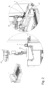
- Fig. 1 schematically shows a laser cutting system with a shuttle table W, which is intended for feeding and removing the workpieces into and out of the laser cutting machine L.
- the system also includes a clearing robot R and a parts sorter T.
- the parts sorter T already has a camera with which the cutting quality can be estimated in addition to part recognition.
- the system can comprise two conveyor belts 23, 24.
- the shuttle table W is used to hold the workpiece.
- the system may include an unloading pallet 27.
- Reference sign 21 denotes a sorting bridge with at least one conveyor belt.
- Reference sign 22 designates a control panel which includes a user interface.
- the unloading robot 20 serves to unload the parts from the shuttle table W after they are cut.
- Fig. 2 shows a similar system with a clearing robot R including a camera system K, which is also used to capture cut surface images.
- the unloading robot 20 can comprise a gripping arm, in particular a sucker, in order to lift a cut part 33 to be measured and sorted.
- the system may include a parts chute 31 which may be located at the sorting bridge.
- a cutting plan for a metal sheet is loaded.
- the machine control system identifies the first straight cut that is suitable for the in-situ camera recording of the cutting edge (measuring signals from a measuring device).
- a straight cut a few cm long is suitable so that the quality parameters can be adequately averaged.
- the cutting process should also be stationary, i.e. the cutting head should not accelerate along the selected route. If this straight cut is carried out, the process monitoring signals, which also include camera recordings of the processing zone by means of a sensor D, as well as the cutting quality q' estimated therefrom (in particular burr height and roughness) are stored.
- the meta information on the sensor signals is also saved, i.e. the coordinates and time of the selected cut and the consecutive part number, as well as the interim results of the real-time cutting quality estimation explained below.
- a cutting plan it can be determined which parts or which cutting edges are suitable for offline measurement.
- the cutting edge should ideally meet the following criteria, according to which the selection parameters are to be set.
- the selected cutting edge sections are evenly distributed over the cutting plan.
- a poor measurement result from the sensor can also be compensated for with a measurement result from the measurement device or the camera (offline). If the quality estimation of measurement 1 (using sensor D) indicates poor quality, this measurement 1 is saved and the part/cut is later measured using sensor 2 (measuring device K). This also gives data from bad cuts, or according to measurement 1 bad cuts and the calibration model can be trained over a larger quality range, which increases the accuracy of the calibration. As a result, the proportion of pseudo errors (false positives: measurement 1 shows bad, measurement 2 shows good) can be reduced.
- the cut metal sheet is transported to the machine and out to the sorting table using an automatic shuttle table.
- a robot arm and a camera K are present at the sorting table.
- the robotic arm sorts the cut sheet metal, stacking the different pieces in appropriate bins (or pallets). If the part for which the suitable cutting edge has been identified for the purpose of in-situ measurement and whose coordinates are known is taken by the robot arm, the selected cutting edge is supplied to the camera K before stacking. The cutting edge is then photographed in a suitable way, for example from different directions. The cutting quality can be determined or measured in a known manner from the photographs.
- the real-time quality estimation based on detected sensor signals and the (in-situ) quality measurement based on measurement signals can be compared. If the two quality values deviate from each other only within acceptable tolerances, typically ⁇ 10 % (the threshold can be parameterised), then the real-time estimation does not need to be readjusted. If the deviation is larger, the real-time estimate should be calibrated in a suitable way.
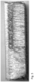
- Figs. 3 and 4 show cutting edges with different cutting qualities. The respective qualities can be clearly distinguished. Thus, in Fig. 3 , the roughness is obviously less on the left than on the right.
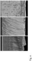
- Fig. 4 shows photos of several cutting samples with different cutting quality. In particular, the strong formation of ridges is evident on the left, while only a slight ridge is present in the middle image. The image on the right shows a cutting edge from below, whereby the formation of burrs can also be clearly seen here. Images from the side (left and middle) as well as from the bottom (right) can be used for the offline quality measurement. Other perspectives are also possible. Samples of known quality (e.g., far left and/or far right) could also be used to calibrate an offline quality measurement based on camera images.
- Samples of known quality e.g., far left and/or far right
- Fig. 5 shows an exemplary cutting head 1 with an exemplary sensor system 5 in the form of a coaxial camera for carrying out a first measurement or for acquiring sensor signals, which leads to the quality estimation result of the real-time estimator ES.
- the exemplary cutting head also shows the focusing lens 2 for the working laser beam 6, which is guided to the cutting head via transport fibre 7, the dichroic deflection mirror 3 for the purpose of decoupling the process observation beam path 4 for process observation via process observation unit/camera 5, apertures and/or filters for process observation optimisation and a unit 9 with which cutting parameters can be adapted, shown as an example using an automatic focusing lens adjustment.
- the workpiece is marked with reference sign 10.
- Fig. 6 shows the calibration system according to a preferred embodiment.
- a calibration module KM is the focus of the invention and is used to calibrate the real-time estimator ES.
- the sensor signals from the sensor are supplied to the real-time estimator ES so that it can output the quality estimation result.
- the measurement signals from the measurement device, in particular from the camera K, are recorded and algorithmically calculated to calculate the quality measurement result q.
- the calibration model is evaluated or applied or evaluated online in the calculation cycle of the real-time estimator ES with quality estimation results q' and the calibration data set k as input (and any intermediate results). It is trained in the calibration module; this is marked in Fig. 6 with the box "calculation of calibration data set”.
- an optical sensor e.g. camera
- the sensor system online, first sensor system
- the measuring device offline, second sensor system
- other sensor types can be used, acoustic sensors, a profilometer, etc.
- the first and second sensors do not necessarily have to be identical. It is thus possible for the first sensor to be a module made up of different optical detectors (camera, photodiodes), optimised for use as fast online sensors.
- the second sensor with the measuring device is optimised for recording the offline cutting quality, for example using a high-resolution camera.
- a camera as a second sensor is that it allows the cut surfaces to be recorded quickly, which is a requirement, for example, when unloading with a robot.
- an optical measuring device for detecting the surface topography, or a mechanical measuring device for measuring roughness (profilometer) or another mechanical measuring system can also be used as a second sensor system. Both detected signal types are then algorithmically converted into a result, namely into the quality estimation result and the quality measurement result, which can then be compared again.
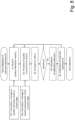
- Fig. 8 shows a flow chart according to a preferred embodiment of the invention for calibrating the real-time estimator ES according to a preferred embodiment of the invention.
- the quality estimation result q' of the real-time estimator ES is loaded in step S1, which was calculated and stored during cutting from sensor signals of the sensor or detector D of a specific cut, typically from video data of an in-process camera.
- sensor signals were recorded, from which a quality estimation result is calculated and stored in step S11 using an estimation algorithm.
- a quality measurement result q is provided in step S2.
- a measurement signal e.g.
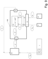
- Fig. 9 shows a schematic representation according to an embodiment variant of another possible implementation of the calibration module KM for the real-time estimator ES, which is designed for - preferably ongoing, continuous -quality estimation online, i.e. during a cutting process or in real time.
- Signals b D preferably optical signals, are continuously supplied to the real-time estimator ES from the sensor D, in particular an in-process camera, which can be attached to the side or coaxially on or in the cutting head, for example, and/or photodiodes. are processed into a quality estimation result q', which - as the name suggests - is intended to estimate the presumed quality of the current cutting process.
- the real-time estimator ES is subjected to a calibration or readjustment on the basis of a cutting quality that is actually measured.
- the measuring device K takes pictures b K of selected cut parts. How many and which parts are to serve as the basis for the recording can be set and configured in a configuration phase-depending on the cutting plan, for example.
- the measuring device or in particular the camera K can be arranged on the laser cutting machine L, separately from the laser cutting machine or on a follow-up system (sorting robot, as shown in Fig. 2 ).
- the camera K can be controlled to take pictures b K according to preconfigurable events. This can happen sporadically.
- the camera K can also be arranged in a mobile device, such as a smartphone or a tablet or the like.
- the load interface E of the calibration module KM is marked in Fig. 9 for loading the quality estimation result q' of the real-time time estimator ES.
- a deflection mirror which can optionally be arranged on the laser head and is used for online process monitoring, is identified by the reference symbol U.
- the camera K is basically independent of the sensor D; 2 separate optical detection devices are therefore provided on different components and/or positions of the system.
- the functionality can also be combined in one device (in particular in the sensor D), so that no separate camera is required.
- the camera K is designed to transmit the captured image data to a first processor P1 of the calibration module KM via a wired or wireless connection - designated interface ss in Fig. 9 .
- the first processor P1 is intended to provide a quality measurement result q of the cutting edge of the finished cut workpiece, the quality measurement result q mainly based on the detection of measurement signals of the cutting edge of the respective finished cut workpiece by means of the camera K and optionally subsequent image analysis by suitable image processing algorithms by means of artificial neural networks (ANNs) is calculated.
- ANNs artificial neural networks
- the term 'quality measurement result' is used because the quality is 'measured' directly or indirectly (indirectly through the camera images b K ) and the calculation is based on actually recorded or measured values.
- ANNs For the use of ANNs, please refer to the following publications: (1) Tatzel L., León F.: Image-based roughness estimation of laser cutting edges with a convolutional neural network, Lane 2020 ; (2) Giusti A. et al.: Image-based Measurement of Material Roughness using Machine Learning Techniques, ISEM 2020 ; (3) De Mitri O. et al.: Image acquisition, evaluation and segmentation of thermal cutting edges using a mobile device, SPIE Photonics 2019 ; (4) Soukup D, Huber-Mörk R (2014) Convolutional Neural Networks for Steel Surface Defect Detection from Photometric Stereo Images. In: Bebis G. et al. (eds) Advances in Visual Computing. ISVC 2014. Lecture Notes in Computer Science, vol 8887. Springer, Ch am.
- the calculation of the quality measurement result can take other measurement data into account in addition or as an alternative to the captured camera image data, such as data from other measuring devices and/or metadata that is also captured with the measurement data captured by sensors and/or machine data that characterise the cutting process of the laser, such as the type of laser, laser power, speed, etc.
- the first processor P1 is intended to calculate a quality measurement result q from the data provided and in particular from the image data of the cutting edge B K .
- a second processor P2 of the calibration module KM is then intended to compare the loaded quality estimation result q', which was provided by the real-time estimator ES, with the actual or real quality measurement result q, which was provided by the first processor P1.
- the second processor P2 is then intended to calculate a calibration data set k for calibrating the real-time estimator ES and to forward the result with the calibration data set k to an output interface A, which is intended to output the calculated calibration data set k.
- the quality measurement result q is calculated algorithmically and automatically on the first processor P1, based on the captured images b K from the camera K.
- a fully or partially manual approach may be performed by a user manually inspecting and evaluating the cutting edge of the cut workpiece.
- suitable input fields can be made available to him/her on a user interface UI, into which he can enter certain values w for selected and/or preconfigured quality parameters, such as roughness, burr formation and others.
- the entered values w are then supplied to the first processor P1, which then executes a simple routine and determines the quality measurement result q* from the entered values.
- a method can be selected for this routine, as described in WO2020069889 A1 .
- a partially manual input can therefore also be used, in which primarily qualitative values such as "good”, "medium”, etc. can be entered. If the online quality estimations can also be assigned to such qualitative values (as suggested above), then the values from online and offline quality can be easily compared with one another or adjusted.
- a combination of the two alternatives mentioned above can also be used.
- the automatically calculated quality measurement result q can be subjected to verification.
- the automatically calculated quality measurement result q is compared with the determined quality measurement result q*, which was based on the user's manual inputs.
- a checking routine is triggered again and the user can be prompted to make another entry, for example. If the deviation persists, this indicates an error in the calculation of the quality measurement result and an error message can be output in order, for example, to initiate an improvement in the calculation function that is executed on the first processor P1 to calculate the quality measurement result q.
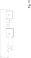
- Fig. 10 shows a schematic representation of the calibration module KM in data exchange with the real-time estimator ES. Both the quality measurement result q and the quality estimation result q' are supplied to the calibration module KM in a highly abstract manner.
- the calibration data set k can then be calculated on the basis of these data sets, which of course relate to the same cutting edge.
- the calibration data set k is then forwarded to the real-time estimator ES for calibration.
- the offline quality measurement of selected cutting edges on selected parts for the purpose of calibrating the online quality estimation is particularly useful for laser machines that have a machine handling system or have one connected to it.
- the cut parts are removed from the cutting table/cleared/stacked and/or restacked by robots (or similar).
- Systems that already have a camera connection during clearing or sorting are particularly suitable. It is easy for the sorting or clearing robot to present the cutting edge of a selected part to the camera. A separate camera might also be beneficial. If an image of the cutting edge is available, the real cutting quality can be determined (roughness, burr,...) and supplied back to the machine.
- the cutting quality includes the following features (not exhaustive), whereby some features are also referred to as quality defects: Roughness, craters, burrs, slag residue, welding.
- the machine can compare (i.e. calibrate) the measured quality (e.g. sporadically via the 2nd camera) of the cutting edge with the quality estimated online via the 1st sensor (e.g. process signals, such as process lights) and, if necessary, in particular but not necessarily, recalibrate or adjust the estimated quality if there is a deviation above a certain threshold.
- the 1st sensor e.g. process signals, such as process lights
- the solution presented enables a fully automatic cutting system, which allows the required/desired cutting quality to be maintained due to the periodic checking (calibration).
- the idea can be integrated into any automation system with at least a 1st online sensor in/on the cutting head for monitoring the process signals and at least a 2nd sensor or camera in a position that enables the quality of a cutting edge to be determined.
- the invention can be used not only for sheet metal cutting systems, but also for other systems involving lasers which require a high degree of quality.
- the components of the calibration module or of the system can be distributed over several physical products (distributed system) with suitable data connections.
Landscapes
- Engineering & Computer Science (AREA)
- Physics & Mathematics (AREA)
- Mechanical Engineering (AREA)
- Optics & Photonics (AREA)
- Plasma & Fusion (AREA)
- Artificial Intelligence (AREA)
- Evolutionary Computation (AREA)
- General Physics & Mathematics (AREA)
- Quality & Reliability (AREA)
- Length Measuring Devices By Optical Means (AREA)
- Laser Beam Processing (AREA)
Claims (20)
- Procédé d'étalonnage d'un estimateur en temps réel (ES) à l'aide d'un module d'étalonnage, l'estimateur en temps réel (ES) étant destiné à l'estimation de la qualité d'un procédé de découpe utilisant une machine de découpe laser (L), comprenant les étapes de procédé suivantes :- détecter au moins un signal de capteur provenant d'au moins un capteur (D) ;- détecter (S21) des signaux de mesure d'un tranchant d'une pièce à usiner découpée finie au moyen d'un dispositif de mesure (K) ;- charger (S1) un résultat d'estimation de qualité (q') de l'estimateur en temps réel (ES), le résultat d'estimation de qualité (q') étant déterminé sur la base d'au moins un signal de capteur provenant de l'au moins un capteur (D) ;- fournir (S2) un résultat de mesure de qualité (q) du tranchant de la pièce à usiner, le résultat de mesure de qualité (q) étant fourni par les signaux de mesure détectés (S21) ;- comparer (S3) le résultat d'estimation de qualité chargé (q') avec le résultat de mesure de qualité fourni (q), un identifiant de position étant attribué et/ou stocké pour les signaux de capteur détectés et pour les signaux de mesure détectés, via lequel les signaux détectés sont clairement identifiables et sont attribués les uns aux autres pour l'étape de comparaison (S3), et en fonction du résultat, uniquement si les écarts déterminés dépassent une valeur seuil préconfigurable, les étapes de procédé suivantes sont exécutées :- calculer (S4) un ensemble de données d'étalonnage (k) pour étalonner (S5) l'estimateur en temps réel (ES), et- étalonner (S5) ou réajuster l'estimateur en temps réel (ES) en utilisant l'ensemble de données d'étalonnage (k).
- Procédé selon la revendication 1, dans lequel l'estimateur en temps réel (ES) est configuré pour exécuter un algorithme d'estimation (S22), et dans lequel l'algorithme d'estimation (S22) calcule le résultat d'estimation de qualité (q') au moins à partir des signaux de capteur détectés provenant de l'au moins un capteur (D).
- Procédé selon la revendication 2, dans lequel l'algorithme d'estimation (S22) de l'estimateur en temps réel (ES) comprend un procédé d'apprentissage automatique, et en particulier un réseau neuronal convolutionnel (CNN) profond.
- Procédé selon l'une quelconque des revendications précédentes, dans lequel l'au moins un capteur (D) est conçu comme un capteur optique et en particulier comme une caméra en cours de traitement et/ou comme une unité photodiode, et/ou dans lequel le dispositif de mesure (K) est une caméra, en particulier une caméra dans un terminal mobile et/ou fixé ou associé à un système d'automatisation, et/ou dans lequel le dispositif de mesure (K) est conçu comme un dispositif de mesure optique et en particulier comme une caméra post-traitement.
- Procédé selon l'une des revendications précédentes, dans lequel la détection du signal de capteur et/ou du signal de mesure peut être configurée, notamment en ce qui concerne un délai d'exécution et/ou un type d'exécution.
- Procédé selon l'une des revendications précédentes, dans lequel des métadonnées sont attribuées et/ou stockées avec les signaux de capteur détectés et/ou les signaux de mesure détectés.
- Procédé selon l'une des revendications précédentes, dans lequel l'ensemble de données d'étalonnage (k) comprend une compensation qui est appliquée au résultat d'estimation de qualité (q') de l'estimateur en temps réel (ES).
- Procédé selon l'une des revendications précédentes, dans lequel l'ensemble de données d'étalonnage (k) est calculé spécifiquement pour le matériau et/ou le processus de découpe.
- Procédé selon l'une des revendications précédentes, dans lequel l'ensemble de données d'étalonnage (k) contient les paramètres entraînés d'un modèle d'étalonnage qui a été entraîné avec des résultats d'estimation de qualité (q') et des résultats de mesure de qualité (q) attribués les uns aux autres.
- Procédé selon la revendication immédiatement précédente, dans lequel le modèle d'étalonnage est sélectionné ou combiné parmi les suivants : modèle de régression, machine à vecteurs de support, forêt aléatoire, arbre à gradient renforcé, réseau neuronal artificiel et/ou dans lequel une approche d'apprentissage d'ensemble avec une combinaison de différents modèles est utilisée.
- Procédé selon l'une des revendications 9 ou 10, dans lequel le modèle d'étalonnage est entraîné en utilisant des résultats intermédiaires supplémentaires stockés de l'estimateur en temps réel comme données d'entraînement et en particulier des résultats intermédiaires de l'estimateur en temps réel sous la forme de valeurs d'activation de neurones d'un réseau neuronal convolutionnel (CNN), disposés devant une couche de sortie.
- Procédé selon la revendication immédiatement précédente, dans lequel le modèle d'étalonnage est entraîné en utilisant des données d'entrée stockées de l'estimateur en temps réel et des résultats de mesure de qualité attribués (q) comme données d'entraînement.
- Procédé selon l'une des revendications 9 à 11, dans lequel le modèle d'étalonnage et/ou l'estimateur en temps réel (ES) est adapté à l'aide d'un algorithme d'apprentissage action-récompense, en particulier à l'aide d'un algorithme d'apprentissage par renforcement.
- Procédé selon l'une des revendications 9 à 12, dans lequel le modèle d'étalonnage et/ou l'estimateur en temps réel (ES) est adapté à de nouveaux matériaux au moyen d'un procédé d'apprentissage par transfert.
- Procédé selon l'une des revendications précédentes, dans lequel la détection (S21) de signaux de capteur d'un tranchant est effectuée sur une découpe d'étalonnage ou sur une découpe productive sans découpe d'étalonnage.
- Procédé selon l'une des revendications précédentes, dans lequel la détection (S21) de signaux de mesure au moyen du capteur (D) s'effectue via un miroir de déviation (U).
- Procédé selon l'une des revendications précédentes, dans lequel le résultat de mesure de qualité (q) est fourni par un ensemble de données d'entrée via une interface utilisateur (IU).
- Procédé selon l'une des revendications précédentes 2 à 17, dans lequel l'algorithme d'estimation (S22) de l'estimateur en temps réel (ES) et les étapes du procédé, en particulier les étapes de chargement (S1), de mise à disposition (S2) et de comparaison (S3), sont exécutées après qu'une découpe d'étalonnage a été effectuée.
- Système comprenant un estimateur en temps réel (ES), un dispositif de mesure (K) et un module d'étalonnage (KM) pour étalonner l'estimateur en temps réel (ES) qui est destiné à l'estimation de la qualité pour un procédé de découpe utilisant une machine de découpe laser (L), le système comprenant au moins un capteur (D), le dispositif de mesure (K) étant configuré pour détecter (S21) des signaux de mesure d'un tranchant d'une pièce à usiner découpée finie, le module d'étalonnage comprenant :- une interface de chargement (E) pour charger un résultat d'estimation de qualité (q') de l'estimateur en temps réel (ES), le résultat d'estimation de qualité (q') étant déterminé sur la base d'au moins un signal de capteur provenant de l'au moins un capteur (D) ;- un premier processeur (P1), qui est configuré pour fournir un résultat de mesure de qualité (q) du tranchant de la pièce à usiner, le résultat de mesure de qualité (q) étant fourni au moyen du dispositif de mesure (K) ;- et dans lequel un second processeur (P2) est configuré pour comparer le résultat d'estimation de qualité chargé (q') avec le résultat de mesure de qualité fourni (q), dans lequel un identifiant de position est attribué et/ou stocké pour les signaux de capteur détectés et pour les signaux de mesure détectés, via lequel les signaux détectés sont clairement identifiables et sont attribués les uns aux autres pour l'étape de comparaison (S3), et en fonction du résultat, uniquement si les écarts déterminés dépassent une valeur seuil préconfigurable :∘ est configuré pour calculer un ensemble de données d'étalonnage (k) pour étalonner l'estimateur en temps réel (ES) et∘ une interface de sortie (A) qui est configurée pour délivrer en sortie l'ensemble de données d'étalonnage calculé (k) et pour utiliser l'ensemble de données d'étalonnage (k) pour étalonner ou réajuster l'estimateur en temps réel (ES).
- Programme informatique, dans lequel le programme informatique peut être chargé dans une unité de mémoire d'une unité de traitement et contient des segments de code de programme pour amener le système de la revendication 19 à exécuter les étapes du procédé d'étalonnage selon l'une quelconque des revendications de procédé précédentes lorsque le programme informatique est exécuté dans l'unité de traitement.
Applications Claiming Priority (2)
| Application Number | Priority Date | Filing Date | Title |
|---|---|---|---|
| EP21184974.0A EP4119284A1 (fr) | 2021-07-12 | 2021-07-12 | Étalonnage d'une estimation qualité pour un procédé de coupe laser |
| PCT/EP2022/064584 WO2023285018A1 (fr) | 2021-07-12 | 2022-05-30 | Étalonnage d'un estimateur de qualité pour un procédé de découpe au laser |
Publications (2)
| Publication Number | Publication Date |
|---|---|
| EP4347175A1 EP4347175A1 (fr) | 2024-04-10 |
| EP4347175B1 true EP4347175B1 (fr) | 2025-03-05 |
Family
ID=76890838
Family Applications (2)
| Application Number | Title | Priority Date | Filing Date |
|---|---|---|---|
| EP21184974.0A Withdrawn EP4119284A1 (fr) | 2021-07-12 | 2021-07-12 | Étalonnage d'une estimation qualité pour un procédé de coupe laser |
| EP22731166.9A Active EP4347175B1 (fr) | 2021-07-12 | 2022-05-30 | Étalonnage d'une estimation qualité pour un procédé de coupe laser |
Family Applications Before (1)
| Application Number | Title | Priority Date | Filing Date |
|---|---|---|---|
| EP21184974.0A Withdrawn EP4119284A1 (fr) | 2021-07-12 | 2021-07-12 | Étalonnage d'une estimation qualité pour un procédé de coupe laser |
Country Status (5)
| Country | Link |
|---|---|
| US (1) | US12434328B2 (fr) |
| EP (2) | EP4119284A1 (fr) |
| JP (1) | JP7592213B2 (fr) |
| CN (1) | CN117715724A (fr) |
| WO (1) | WO2023285018A1 (fr) |
Families Citing this family (14)
| Publication number | Priority date | Publication date | Assignee | Title |
|---|---|---|---|---|
| DE102022113851A1 (de) * | 2022-06-01 | 2023-12-07 | Ersa Gmbh | System zur Bestimmung von Verschmutzungskoeffizienten und/oder Verschmutzungsgraden insbesondere beim Reflowlöten von Leiterplatten und zugehörige Auswerteinheit |
| DE102023103704A1 (de) * | 2023-02-15 | 2024-08-22 | TRUMPF Werkzeugmaschinen SE + Co. KG | Verfahren zum analysieren eines geräuschs, verfahren zum trainieren einer künstlichen intelligenz sowie verfahren zum ermitteln einer schnittabrissposition |
| DE102023126702A1 (de) * | 2023-09-29 | 2025-04-03 | TRUMPF Werkzeugmaschinen SE + Co. KG | System und Verfahren zur Einstellung von Schneidparameterwerten einer Laserschneidmaschine für Blech |
| DE102023130977A1 (de) * | 2023-11-08 | 2025-05-08 | TRUMPF Werkzeugmaschinen SE + Co. KG | Verfahren zum Adaptieren eines trainierten Machine-Learning-Modells einer Werkzeugmaschine, Verfahren zum Betreiben einer Werkzeugmaschine, Werkzeugmaschine, Computerprogramm und computerlesbares Medium |
| DE102023135211A1 (de) * | 2023-12-14 | 2025-06-18 | TRUMPF Werkzeugmaschinen SE + Co. KG | Verfahren und Vorrichtung zum Analysieren einer Schnittfläche eines Werkstücks |
| JP2025107723A (ja) * | 2024-01-09 | 2025-07-22 | Jfeスチール株式会社 | 材料品質推定モデルの作成方法、材料品質推定方法、材料品質推定モデルの作成装置、材料品質推定装置および材料品質推定モデルの作成システム |
| DE102024108416A1 (de) | 2024-03-25 | 2025-09-25 | TRUMPF Werkzeugmaschinen SE + Co. KG | Verfahren zum Betreiben einer Laserschneidanlage, Laserschneidanlage, System |
| CN118060610B (zh) * | 2024-04-19 | 2024-08-23 | 泰兴市瑞之宁金属制品有限公司 | 一种消防用金属制品加工用切割设备 |
| US20250345880A1 (en) * | 2024-05-08 | 2025-11-13 | Magna International Inc. | Method of tracking a blank edge for laser cutting |
| DE102024121858A1 (de) * | 2024-07-31 | 2026-02-05 | TRUMPF Werkzeugmaschinen SE + Co. KG | Verfahren zum Bestimmen einer Schnittqualität und Bearbeitungsmaschine |
| EP4718374A1 (fr) * | 2024-09-30 | 2026-04-01 | Bystronic Laser AG | Détection d'anomalies de feuille pour machine laser |
| CN119359738B (zh) * | 2024-12-25 | 2025-03-28 | 深圳艾利佳材料科技有限公司 | 一种图像处理的钛金属分割方法及系统 |
| DE102025103474B3 (de) | 2025-01-30 | 2026-03-26 | Dr. Ing. H.C. F. Porsche Aktiengesellschaft | Verfahren zum Schneiden einer Bandage, die einen kohlefaserverstärkten Kunststoff umfasst |
| CN120637217A (zh) * | 2025-06-16 | 2025-09-12 | 昆山钰源宏机电设备有限公司 | 一种支持自主纠偏的半导体构件裁切控制方法、系统 |
Family Cites Families (14)
| Publication number | Priority date | Publication date | Assignee | Title |
|---|---|---|---|---|
| US4866641A (en) * | 1987-04-24 | 1989-09-12 | Laser Alignment, Inc. | Apparatus and method for controlling a hydraulic excavator |
| JP3660328B2 (ja) * | 2002-06-21 | 2005-06-15 | ファナック株式会社 | レーザ加工機 |
| IT1397985B1 (it) * | 2010-02-08 | 2013-02-04 | Prima Ind Spa | Procedimento di monitoraggio della qualità di processi di lavorazione laser e relativo sistema |
| WO2012000648A1 (fr) * | 2010-06-28 | 2012-01-05 | Precitec Kg | Procédé de commande en boucle fermée d'une opération de traitement laser et tête de traitement de matériau au laser utilisant ce procédé |
| US9529343B2 (en) | 2010-06-30 | 2016-12-27 | Trumpf Werkzeugmaschinen Gmbh + Co. Kg | Dialogue system and method for examining machining processes |
| PL3412399T3 (pl) | 2015-10-23 | 2021-10-25 | Bystronic Laser Ag | Sposób kontrolowania procesów cięcia laserowego w zakresie dużej mocy z przerywaniem procesu cięcia, odpowiednie urządzenie i produkt w postaci programu komputerowego |
| JP6625914B2 (ja) * | 2016-03-17 | 2019-12-25 | ファナック株式会社 | 機械学習装置、レーザ加工システムおよび機械学習方法 |
| US10234848B2 (en) * | 2017-05-24 | 2019-03-19 | Relativity Space, Inc. | Real-time adaptive control of additive manufacturing processes using machine learning |
| DE102018216873A1 (de) | 2018-10-01 | 2020-04-02 | Trumpf Werkzeugmaschinen Gmbh + Co. Kg | Verfahren und Vorrichtung zur Bearbeitung eines Werkstücks |
| EP3671373A1 (fr) | 2018-12-19 | 2020-06-24 | Bystronic Laser AG | Méthode de prédiction pour prédire le résultat de l'usinage pour une méthode d'usinage à laser |
| JP6972047B2 (ja) * | 2019-01-31 | 2021-11-24 | 三菱電機株式会社 | 加工条件解析装置、レーザ加工装置、レーザ加工システムおよび加工条件解析方法 |
| DE102019209088A1 (de) | 2019-06-24 | 2020-12-24 | Trumpf Werkzeugmaschinen Gmbh + Co. Kg | Verfahren zum Bewerten einer Laserschnittkante, mobiles Endgerät und System |
| DE102019127900B3 (de) | 2019-10-16 | 2021-04-01 | Precitec Gmbh & Co. Kg | Verfahren zur Überwachung eines Laserbearbeitungsprozesses zur Bearbeitung von Werkstücken |
| EP3885069A1 (fr) | 2020-03-25 | 2021-09-29 | Bystronic Laser AG | Contrôle qualité d'un processus d'usinage laser au moyen d'apprentissage automatique |
-
2021
- 2021-07-12 EP EP21184974.0A patent/EP4119284A1/fr not_active Withdrawn
-
2022
- 2022-05-30 US US18/577,615 patent/US12434328B2/en active Active
- 2022-05-30 EP EP22731166.9A patent/EP4347175B1/fr active Active
- 2022-05-30 CN CN202280049237.1A patent/CN117715724A/zh active Pending
- 2022-05-30 JP JP2024501103A patent/JP7592213B2/ja active Active
- 2022-05-30 WO PCT/EP2022/064584 patent/WO2023285018A1/fr not_active Ceased
Also Published As
| Publication number | Publication date |
|---|---|
| CN117715724A (zh) | 2024-03-15 |
| EP4119284A1 (fr) | 2023-01-18 |
| WO2023285018A1 (fr) | 2023-01-19 |
| EP4347175A1 (fr) | 2024-04-10 |
| US12434328B2 (en) | 2025-10-07 |
| JP2024528597A (ja) | 2024-07-30 |
| JP7592213B2 (ja) | 2024-11-29 |
| US20240261890A1 (en) | 2024-08-08 |
Similar Documents
| Publication | Publication Date | Title |
|---|---|---|
| EP4347175B1 (fr) | Étalonnage d'une estimation qualité pour un procédé de coupe laser | |
| US11224938B2 (en) | Laser process monitoring | |
| EP4126437B1 (fr) | Contrôle qualité d'un processus d'usinage laser au moyen d'apprentissage automatique | |
| US11150200B1 (en) | Workpiece inspection and defect detection system indicating number of defect images for training | |
| CN102292187B (zh) | 用于监控要在工件上实施的激光加工过程的方法和装置以及具有这种装置的激光加工头 | |
| US11430105B2 (en) | Workpiece inspection and defect detection system including monitoring of workpiece images | |
| JP5912125B2 (ja) | ウェブベース材料における不均一性の高速処理と検出 | |
| US20180307203A1 (en) | Machining defect factor estimation device | |
| US12521817B2 (en) | Determination of contour fidelity for a laser cutting machine | |
| WO2023280679A1 (fr) | Détection automatique de soudure pour un procédé de soudage | |
| CN114502313A (zh) | 用于借助激光束在工件上执行加工工序的激光加工系统和用于监控工件上的借助激光束的加工工序的方法 | |
| Bourlesas et al. | Over-deposition assessment of Direct Energy Deposition (DED) using melt pool geometric features and Machine Learning | |
| JP7105377B2 (ja) | 金属加工装置におけるノズルの状態又はタイプの特定 | |
| Schmitz et al. | Enabling rewards for reinforcement learning in laser beam welding processes through deep learning | |
| US20260115828A1 (en) | Method and device for optimizing an loc watchdog (loss of cut watchdog) for a laser cutting machine | |
| EP4597246A1 (fr) | Dispositif d'analyse de facteur et procédé d'analyse de facteur | |
| Nanthini et al. | Integrating Computer Vision and Deep Learning for Automated Object Diagnosis and Repair | |
| US20250319520A1 (en) | Method for additive manufacturing machine and process qualification and verifiction | |
| Guerra et al. | Hierarchical vision-driven automatic control of quality and speed in fusion laser cutting | |
| genannt Wersborg et al. | Multiple sensors and artificial neural networks in a cognitive technical system for laser welding | |
| CN121776725A (zh) | 基于双臂协同的人形机器人焊接质量控制方法及装置 | |
| HK1164786B (en) | Method and device for monitoring a laser processing operation to be performed on a workpiece and laser processing head having such a device |
Legal Events
| Date | Code | Title | Description |
|---|---|---|---|
| STAA | Information on the status of an ep patent application or granted ep patent |
Free format text: STATUS: UNKNOWN |
|
| STAA | Information on the status of an ep patent application or granted ep patent |
Free format text: STATUS: THE INTERNATIONAL PUBLICATION HAS BEEN MADE |
|
| PUAI | Public reference made under article 153(3) epc to a published international application that has entered the european phase |
Free format text: ORIGINAL CODE: 0009012 |
|
| STAA | Information on the status of an ep patent application or granted ep patent |
Free format text: STATUS: REQUEST FOR EXAMINATION WAS MADE |
|
| 17P | Request for examination filed |
Effective date: 20240105 |
|
| AK | Designated contracting states |
Kind code of ref document: A1 Designated state(s): AL AT BE BG CH CY CZ DE DK EE ES FI FR GB GR HR HU IE IS IT LI LT LU LV MC MK MT NL NO PL PT RO RS SE SI SK SM TR |
|
| DAV | Request for validation of the european patent (deleted) | ||
| DAX | Request for extension of the european patent (deleted) | ||
| GRAP | Despatch of communication of intention to grant a patent |
Free format text: ORIGINAL CODE: EPIDOSNIGR1 |
|
| STAA | Information on the status of an ep patent application or granted ep patent |
Free format text: STATUS: GRANT OF PATENT IS INTENDED |
|
| INTG | Intention to grant announced |
Effective date: 20241031 |
|
| GRAS | Grant fee paid |
Free format text: ORIGINAL CODE: EPIDOSNIGR3 |
|
| GRAA | (expected) grant |
Free format text: ORIGINAL CODE: 0009210 |
|
| STAA | Information on the status of an ep patent application or granted ep patent |
Free format text: STATUS: THE PATENT HAS BEEN GRANTED |
|
| AK | Designated contracting states |
Kind code of ref document: B1 Designated state(s): AL AT BE BG CH CY CZ DE DK EE ES FI FR GB GR HR HU IE IS IT LI LT LU LV MC MK MT NL NO PL PT RO RS SE SI SK SM TR |
|
| REG | Reference to a national code |
Ref country code: GB Ref legal event code: FG4D |
|
| REG | Reference to a national code |
Ref country code: CH Ref legal event code: EP |
|
| REG | Reference to a national code |
Ref country code: DE Ref legal event code: R096 Ref document number: 602022011488 Country of ref document: DE |
|
| P01 | Opt-out of the competence of the unified patent court (upc) registered |
Free format text: CASE NUMBER: APP_8493/2025 Effective date: 20250219 |
|
| REG | Reference to a national code |
Ref country code: IE Ref legal event code: FG4D |
|
| PG25 | Lapsed in a contracting state [announced via postgrant information from national office to epo] |
Ref country code: RS Free format text: LAPSE BECAUSE OF FAILURE TO SUBMIT A TRANSLATION OF THE DESCRIPTION OR TO PAY THE FEE WITHIN THE PRESCRIBED TIME-LIMIT Effective date: 20250605 |
|
| PG25 | Lapsed in a contracting state [announced via postgrant information from national office to epo] |
Ref country code: FI Free format text: LAPSE BECAUSE OF FAILURE TO SUBMIT A TRANSLATION OF THE DESCRIPTION OR TO PAY THE FEE WITHIN THE PRESCRIBED TIME-LIMIT Effective date: 20250305 |
|
| PGFP | Annual fee paid to national office [announced via postgrant information from national office to epo] |
Ref country code: DE Payment date: 20250402 Year of fee payment: 4 |
|
| REG | Reference to a national code |
Ref country code: NL Ref legal event code: MP Effective date: 20250305 |
|
| PG25 | Lapsed in a contracting state [announced via postgrant information from national office to epo] |
Ref country code: ES Free format text: LAPSE BECAUSE OF FAILURE TO SUBMIT A TRANSLATION OF THE DESCRIPTION OR TO PAY THE FEE WITHIN THE PRESCRIBED TIME-LIMIT Effective date: 20250305 |
|
| REG | Reference to a national code |
Ref country code: LT Ref legal event code: MG9D |
|
| PG25 | Lapsed in a contracting state [announced via postgrant information from national office to epo] |
Ref country code: NO Free format text: LAPSE BECAUSE OF FAILURE TO SUBMIT A TRANSLATION OF THE DESCRIPTION OR TO PAY THE FEE WITHIN THE PRESCRIBED TIME-LIMIT Effective date: 20250605 |
|
| PGFP | Annual fee paid to national office [announced via postgrant information from national office to epo] |
Ref country code: IT Payment date: 20250531 Year of fee payment: 4 |
|
| PG25 | Lapsed in a contracting state [announced via postgrant information from national office to epo] |
Ref country code: HR Free format text: LAPSE BECAUSE OF FAILURE TO SUBMIT A TRANSLATION OF THE DESCRIPTION OR TO PAY THE FEE WITHIN THE PRESCRIBED TIME-LIMIT Effective date: 20250305 |
|
| PG25 | Lapsed in a contracting state [announced via postgrant information from national office to epo] |
Ref country code: LV Free format text: LAPSE BECAUSE OF FAILURE TO SUBMIT A TRANSLATION OF THE DESCRIPTION OR TO PAY THE FEE WITHIN THE PRESCRIBED TIME-LIMIT Effective date: 20250305 |
|
| PG25 | Lapsed in a contracting state [announced via postgrant information from national office to epo] |
Ref country code: BG Free format text: LAPSE BECAUSE OF FAILURE TO SUBMIT A TRANSLATION OF THE DESCRIPTION OR TO PAY THE FEE WITHIN THE PRESCRIBED TIME-LIMIT Effective date: 20250305 Ref country code: GR Free format text: LAPSE BECAUSE OF FAILURE TO SUBMIT A TRANSLATION OF THE DESCRIPTION OR TO PAY THE FEE WITHIN THE PRESCRIBED TIME-LIMIT Effective date: 20250606 |
|
| PGFP | Annual fee paid to national office [announced via postgrant information from national office to epo] |
Ref country code: CH Payment date: 20250601 Year of fee payment: 4 |
|
| REG | Reference to a national code |
Ref country code: AT Ref legal event code: MK05 Ref document number: 1772506 Country of ref document: AT Kind code of ref document: T Effective date: 20250305 |
|
| PG25 | Lapsed in a contracting state [announced via postgrant information from national office to epo] |
Ref country code: NL Free format text: LAPSE BECAUSE OF FAILURE TO SUBMIT A TRANSLATION OF THE DESCRIPTION OR TO PAY THE FEE WITHIN THE PRESCRIBED TIME-LIMIT Effective date: 20250305 |
|
| PG25 | Lapsed in a contracting state [announced via postgrant information from national office to epo] |
Ref country code: SE Free format text: LAPSE BECAUSE OF FAILURE TO SUBMIT A TRANSLATION OF THE DESCRIPTION OR TO PAY THE FEE WITHIN THE PRESCRIBED TIME-LIMIT Effective date: 20250305 |
|
| PG25 | Lapsed in a contracting state [announced via postgrant information from national office to epo] |
Ref country code: SM Free format text: LAPSE BECAUSE OF FAILURE TO SUBMIT A TRANSLATION OF THE DESCRIPTION OR TO PAY THE FEE WITHIN THE PRESCRIBED TIME-LIMIT Effective date: 20250305 |
|
| PG25 | Lapsed in a contracting state [announced via postgrant information from national office to epo] |
Ref country code: PT Free format text: LAPSE BECAUSE OF FAILURE TO SUBMIT A TRANSLATION OF THE DESCRIPTION OR TO PAY THE FEE WITHIN THE PRESCRIBED TIME-LIMIT Effective date: 20250707 |
|
| PG25 | Lapsed in a contracting state [announced via postgrant information from national office to epo] |
Ref country code: PL Free format text: LAPSE BECAUSE OF FAILURE TO SUBMIT A TRANSLATION OF THE DESCRIPTION OR TO PAY THE FEE WITHIN THE PRESCRIBED TIME-LIMIT Effective date: 20250305 |
|
| PG25 | Lapsed in a contracting state [announced via postgrant information from national office to epo] |
Ref country code: AT Free format text: LAPSE BECAUSE OF FAILURE TO SUBMIT A TRANSLATION OF THE DESCRIPTION OR TO PAY THE FEE WITHIN THE PRESCRIBED TIME-LIMIT Effective date: 20250305 |
|
| PG25 | Lapsed in a contracting state [announced via postgrant information from national office to epo] |
Ref country code: EE Free format text: LAPSE BECAUSE OF FAILURE TO SUBMIT A TRANSLATION OF THE DESCRIPTION OR TO PAY THE FEE WITHIN THE PRESCRIBED TIME-LIMIT Effective date: 20250305 Ref country code: CZ Free format text: LAPSE BECAUSE OF FAILURE TO SUBMIT A TRANSLATION OF THE DESCRIPTION OR TO PAY THE FEE WITHIN THE PRESCRIBED TIME-LIMIT Effective date: 20250305 |
|
| PG25 | Lapsed in a contracting state [announced via postgrant information from national office to epo] |
Ref country code: RO Free format text: LAPSE BECAUSE OF FAILURE TO SUBMIT A TRANSLATION OF THE DESCRIPTION OR TO PAY THE FEE WITHIN THE PRESCRIBED TIME-LIMIT Effective date: 20250305 |
|
| PG25 | Lapsed in a contracting state [announced via postgrant information from national office to epo] |
Ref country code: SK Free format text: LAPSE BECAUSE OF FAILURE TO SUBMIT A TRANSLATION OF THE DESCRIPTION OR TO PAY THE FEE WITHIN THE PRESCRIBED TIME-LIMIT Effective date: 20250305 |
|
| PG25 | Lapsed in a contracting state [announced via postgrant information from national office to epo] |
Ref country code: IS Free format text: LAPSE BECAUSE OF FAILURE TO SUBMIT A TRANSLATION OF THE DESCRIPTION OR TO PAY THE FEE WITHIN THE PRESCRIBED TIME-LIMIT Effective date: 20250705 |
|
| REG | Reference to a national code |
Ref country code: DE Ref legal event code: R097 Ref document number: 602022011488 Country of ref document: DE |
|
| PLBE | No opposition filed within time limit |
Free format text: ORIGINAL CODE: 0009261 |
|
| STAA | Information on the status of an ep patent application or granted ep patent |
Free format text: STATUS: NO OPPOSITION FILED WITHIN TIME LIMIT |
|
| PG25 | Lapsed in a contracting state [announced via postgrant information from national office to epo] |
Ref country code: DK Free format text: LAPSE BECAUSE OF FAILURE TO SUBMIT A TRANSLATION OF THE DESCRIPTION OR TO PAY THE FEE WITHIN THE PRESCRIBED TIME-LIMIT Effective date: 20250305 |
|
| REG | Reference to a national code |
Ref country code: CH Ref legal event code: L10 Free format text: ST27 STATUS EVENT CODE: U-0-0-L10-L00 (AS PROVIDED BY THE NATIONAL OFFICE) Effective date: 20260114 |
|
| PG25 | Lapsed in a contracting state [announced via postgrant information from national office to epo] |
Ref country code: LU Free format text: LAPSE BECAUSE OF NON-PAYMENT OF DUE FEES Effective date: 20250530 |
|
| REG | Reference to a national code |
Ref country code: BE Ref legal event code: MM Effective date: 20250531 |
|
| PG25 | Lapsed in a contracting state [announced via postgrant information from national office to epo] |
Ref country code: MC Free format text: LAPSE BECAUSE OF FAILURE TO SUBMIT A TRANSLATION OF THE DESCRIPTION OR TO PAY THE FEE WITHIN THE PRESCRIBED TIME-LIMIT Effective date: 20250305 |
|
| 26N | No opposition filed |
Effective date: 20251208 |
|
| PGFP | Annual fee paid to national office [announced via postgrant information from national office to epo] |
Ref country code: GB Payment date: 20260312 Year of fee payment: 5 |
|
| PG25 | Lapsed in a contracting state [announced via postgrant information from national office to epo] |
Ref country code: IE Free format text: LAPSE BECAUSE OF NON-PAYMENT OF DUE FEES Effective date: 20250530 |
|
| PG25 | Lapsed in a contracting state [announced via postgrant information from national office to epo] |
Ref country code: BE Free format text: LAPSE BECAUSE OF NON-PAYMENT OF DUE FEES Effective date: 20250531 |
|
| PG25 | Lapsed in a contracting state [announced via postgrant information from national office to epo] |
Ref country code: FR Free format text: LAPSE BECAUSE OF NON-PAYMENT OF DUE FEES Effective date: 20250531 |