EP4347336B1 - Équipement électropneumatique d'un véhicule comprenant un système de freinage autonome alimenté par précaution avec une pression de secours - Google Patents
Équipement électropneumatique d'un véhicule comprenant un système de freinage autonome alimenté par précaution avec une pression de secours Download PDFInfo
- Publication number
- EP4347336B1 EP4347336B1 EP22730178.5A EP22730178A EP4347336B1 EP 4347336 B1 EP4347336 B1 EP 4347336B1 EP 22730178 A EP22730178 A EP 22730178A EP 4347336 B1 EP4347336 B1 EP 4347336B1
- Authority
- EP
- European Patent Office
- Prior art keywords
- brake
- pressure
- control
- pneumatic
- service brake
- Prior art date
- Legal status (The legal status is an assumption and is not a legal conclusion. Google has not performed a legal analysis and makes no representation as to the accuracy of the status listed.)
- Active
Links
Images

Classifications
-
- B—PERFORMING OPERATIONS; TRANSPORTING
- B60—VEHICLES IN GENERAL
- B60T—VEHICLE BRAKE CONTROL SYSTEMS OR PARTS THEREOF; BRAKE CONTROL SYSTEMS OR PARTS THEREOF, IN GENERAL; ARRANGEMENT OF BRAKING ELEMENTS ON VEHICLES IN GENERAL; PORTABLE DEVICES FOR PREVENTING UNWANTED MOVEMENT OF VEHICLES; VEHICLE MODIFICATIONS TO FACILITATE COOLING OF BRAKES
- B60T8/00—Arrangements for adjusting wheel-braking force to meet varying vehicular or ground-surface conditions, e.g. limiting or varying distribution of braking force
- B60T8/17—Using electrical or electronic regulation means to control braking
- B60T8/172—Determining control parameters used in the regulation, e.g. by calculations involving measured or detected parameters
-
- B—PERFORMING OPERATIONS; TRANSPORTING
- B60—VEHICLES IN GENERAL
- B60T—VEHICLE BRAKE CONTROL SYSTEMS OR PARTS THEREOF; BRAKE CONTROL SYSTEMS OR PARTS THEREOF, IN GENERAL; ARRANGEMENT OF BRAKING ELEMENTS ON VEHICLES IN GENERAL; PORTABLE DEVICES FOR PREVENTING UNWANTED MOVEMENT OF VEHICLES; VEHICLE MODIFICATIONS TO FACILITATE COOLING OF BRAKES
- B60T13/00—Transmitting braking action from initiating means to ultimate brake actuator with power assistance or drive; Brake systems incorporating such transmitting means, e.g. air-pressure brake systems
- B60T13/10—Transmitting braking action from initiating means to ultimate brake actuator with power assistance or drive; Brake systems incorporating such transmitting means, e.g. air-pressure brake systems with fluid assistance, drive, or release
- B60T13/24—Transmitting braking action from initiating means to ultimate brake actuator with power assistance or drive; Brake systems incorporating such transmitting means, e.g. air-pressure brake systems with fluid assistance, drive, or release the fluid being gaseous
- B60T13/26—Compressed-air systems
- B60T13/36—Compressed-air systems direct, i.e. brakes applied directly by compressed air
-
- B—PERFORMING OPERATIONS; TRANSPORTING
- B60—VEHICLES IN GENERAL
- B60T—VEHICLE BRAKE CONTROL SYSTEMS OR PARTS THEREOF; BRAKE CONTROL SYSTEMS OR PARTS THEREOF, IN GENERAL; ARRANGEMENT OF BRAKING ELEMENTS ON VEHICLES IN GENERAL; PORTABLE DEVICES FOR PREVENTING UNWANTED MOVEMENT OF VEHICLES; VEHICLE MODIFICATIONS TO FACILITATE COOLING OF BRAKES
- B60T13/00—Transmitting braking action from initiating means to ultimate brake actuator with power assistance or drive; Brake systems incorporating such transmitting means, e.g. air-pressure brake systems
- B60T13/10—Transmitting braking action from initiating means to ultimate brake actuator with power assistance or drive; Brake systems incorporating such transmitting means, e.g. air-pressure brake systems with fluid assistance, drive, or release
- B60T13/58—Combined or convertible systems
- B60T13/581—Combined or convertible systems both hydraulic and pneumatic
-
- B—PERFORMING OPERATIONS; TRANSPORTING
- B60—VEHICLES IN GENERAL
- B60T—VEHICLE BRAKE CONTROL SYSTEMS OR PARTS THEREOF; BRAKE CONTROL SYSTEMS OR PARTS THEREOF, IN GENERAL; ARRANGEMENT OF BRAKING ELEMENTS ON VEHICLES IN GENERAL; PORTABLE DEVICES FOR PREVENTING UNWANTED MOVEMENT OF VEHICLES; VEHICLE MODIFICATIONS TO FACILITATE COOLING OF BRAKES
- B60T13/00—Transmitting braking action from initiating means to ultimate brake actuator with power assistance or drive; Brake systems incorporating such transmitting means, e.g. air-pressure brake systems
- B60T13/10—Transmitting braking action from initiating means to ultimate brake actuator with power assistance or drive; Brake systems incorporating such transmitting means, e.g. air-pressure brake systems with fluid assistance, drive, or release
- B60T13/66—Electrical control in fluid-pressure brake systems
- B60T13/662—Electrical control in fluid-pressure brake systems characterised by specified functions of the control system components
-
- B—PERFORMING OPERATIONS; TRANSPORTING
- B60—VEHICLES IN GENERAL
- B60T—VEHICLE BRAKE CONTROL SYSTEMS OR PARTS THEREOF; BRAKE CONTROL SYSTEMS OR PARTS THEREOF, IN GENERAL; ARRANGEMENT OF BRAKING ELEMENTS ON VEHICLES IN GENERAL; PORTABLE DEVICES FOR PREVENTING UNWANTED MOVEMENT OF VEHICLES; VEHICLE MODIFICATIONS TO FACILITATE COOLING OF BRAKES
- B60T13/00—Transmitting braking action from initiating means to ultimate brake actuator with power assistance or drive; Brake systems incorporating such transmitting means, e.g. air-pressure brake systems
- B60T13/10—Transmitting braking action from initiating means to ultimate brake actuator with power assistance or drive; Brake systems incorporating such transmitting means, e.g. air-pressure brake systems with fluid assistance, drive, or release
- B60T13/66—Electrical control in fluid-pressure brake systems
- B60T13/68—Electrical control in fluid-pressure brake systems by electrically-controlled valves
- B60T13/683—Electrical control in fluid-pressure brake systems by electrically-controlled valves in pneumatic systems or parts thereof
-
- B—PERFORMING OPERATIONS; TRANSPORTING
- B60—VEHICLES IN GENERAL
- B60T—VEHICLE BRAKE CONTROL SYSTEMS OR PARTS THEREOF; BRAKE CONTROL SYSTEMS OR PARTS THEREOF, IN GENERAL; ARRANGEMENT OF BRAKING ELEMENTS ON VEHICLES IN GENERAL; PORTABLE DEVICES FOR PREVENTING UNWANTED MOVEMENT OF VEHICLES; VEHICLE MODIFICATIONS TO FACILITATE COOLING OF BRAKES
- B60T15/00—Construction arrangement, or operation of valves incorporated in power brake systems and not covered by groups B60T11/00 or B60T13/00
- B60T15/02—Application and release valves
- B60T15/04—Driver's valves
- B60T15/043—Driver's valves controlling service pressure brakes
-
- B—PERFORMING OPERATIONS; TRANSPORTING
- B60—VEHICLES IN GENERAL
- B60T—VEHICLE BRAKE CONTROL SYSTEMS OR PARTS THEREOF; BRAKE CONTROL SYSTEMS OR PARTS THEREOF, IN GENERAL; ARRANGEMENT OF BRAKING ELEMENTS ON VEHICLES IN GENERAL; PORTABLE DEVICES FOR PREVENTING UNWANTED MOVEMENT OF VEHICLES; VEHICLE MODIFICATIONS TO FACILITATE COOLING OF BRAKES
- B60T15/00—Construction arrangement, or operation of valves incorporated in power brake systems and not covered by groups B60T11/00 or B60T13/00
- B60T15/02—Application and release valves
- B60T15/18—Triple or other relay valves which allow step-wise application or release and which are actuated by brake-pipe pressure variation to connect brake cylinders or equivalent to compressed air or vacuum source or atmosphere
-
- B—PERFORMING OPERATIONS; TRANSPORTING
- B60—VEHICLES IN GENERAL
- B60T—VEHICLE BRAKE CONTROL SYSTEMS OR PARTS THEREOF; BRAKE CONTROL SYSTEMS OR PARTS THEREOF, IN GENERAL; ARRANGEMENT OF BRAKING ELEMENTS ON VEHICLES IN GENERAL; PORTABLE DEVICES FOR PREVENTING UNWANTED MOVEMENT OF VEHICLES; VEHICLE MODIFICATIONS TO FACILITATE COOLING OF BRAKES
- B60T17/00—Component parts, details, or accessories of power brake systems not covered by groups B60T8/00, B60T13/00 or B60T15/00, or presenting other characteristic features
- B60T17/18—Safety devices; Monitoring
- B60T17/22—Devices for monitoring or checking brake systems; Signal devices
- B60T17/221—Procedure or apparatus for checking or keeping in a correct functioning condition of brake systems
-
- B—PERFORMING OPERATIONS; TRANSPORTING
- B60—VEHICLES IN GENERAL
- B60T—VEHICLE BRAKE CONTROL SYSTEMS OR PARTS THEREOF; BRAKE CONTROL SYSTEMS OR PARTS THEREOF, IN GENERAL; ARRANGEMENT OF BRAKING ELEMENTS ON VEHICLES IN GENERAL; PORTABLE DEVICES FOR PREVENTING UNWANTED MOVEMENT OF VEHICLES; VEHICLE MODIFICATIONS TO FACILITATE COOLING OF BRAKES
- B60T7/00—Brake-action initiating means
- B60T7/12—Brake-action initiating means for automatic initiation; for initiation not subject to will of driver or passenger
-
- B—PERFORMING OPERATIONS; TRANSPORTING
- B60—VEHICLES IN GENERAL
- B60T—VEHICLE BRAKE CONTROL SYSTEMS OR PARTS THEREOF; BRAKE CONTROL SYSTEMS OR PARTS THEREOF, IN GENERAL; ARRANGEMENT OF BRAKING ELEMENTS ON VEHICLES IN GENERAL; PORTABLE DEVICES FOR PREVENTING UNWANTED MOVEMENT OF VEHICLES; VEHICLE MODIFICATIONS TO FACILITATE COOLING OF BRAKES
- B60T2201/00—Particular use of vehicle brake systems; Special systems using also the brakes; Special software modules within the brake system controller
- B60T2201/03—Brake assistants
-
- B—PERFORMING OPERATIONS; TRANSPORTING
- B60—VEHICLES IN GENERAL
- B60T—VEHICLE BRAKE CONTROL SYSTEMS OR PARTS THEREOF; BRAKE CONTROL SYSTEMS OR PARTS THEREOF, IN GENERAL; ARRANGEMENT OF BRAKING ELEMENTS ON VEHICLES IN GENERAL; PORTABLE DEVICES FOR PREVENTING UNWANTED MOVEMENT OF VEHICLES; VEHICLE MODIFICATIONS TO FACILITATE COOLING OF BRAKES
- B60T2220/00—Monitoring, detecting driver behaviour; Signalling thereof; Counteracting thereof
- B60T2220/04—Pedal travel sensor, stroke sensor; Sensing brake request
-
- B—PERFORMING OPERATIONS; TRANSPORTING
- B60—VEHICLES IN GENERAL
- B60T—VEHICLE BRAKE CONTROL SYSTEMS OR PARTS THEREOF; BRAKE CONTROL SYSTEMS OR PARTS THEREOF, IN GENERAL; ARRANGEMENT OF BRAKING ELEMENTS ON VEHICLES IN GENERAL; PORTABLE DEVICES FOR PREVENTING UNWANTED MOVEMENT OF VEHICLES; VEHICLE MODIFICATIONS TO FACILITATE COOLING OF BRAKES
- B60T2250/00—Monitoring, detecting, estimating vehicle conditions
- B60T2250/02—Vehicle mass
-
- B—PERFORMING OPERATIONS; TRANSPORTING
- B60—VEHICLES IN GENERAL
- B60T—VEHICLE BRAKE CONTROL SYSTEMS OR PARTS THEREOF; BRAKE CONTROL SYSTEMS OR PARTS THEREOF, IN GENERAL; ARRANGEMENT OF BRAKING ELEMENTS ON VEHICLES IN GENERAL; PORTABLE DEVICES FOR PREVENTING UNWANTED MOVEMENT OF VEHICLES; VEHICLE MODIFICATIONS TO FACILITATE COOLING OF BRAKES
- B60T2270/00—Further aspects of brake control systems not otherwise provided for
- B60T2270/40—Failsafe aspects of brake control systems
- B60T2270/402—Back-up
-
- B—PERFORMING OPERATIONS; TRANSPORTING
- B60—VEHICLES IN GENERAL
- B60T—VEHICLE BRAKE CONTROL SYSTEMS OR PARTS THEREOF; BRAKE CONTROL SYSTEMS OR PARTS THEREOF, IN GENERAL; ARRANGEMENT OF BRAKING ELEMENTS ON VEHICLES IN GENERAL; PORTABLE DEVICES FOR PREVENTING UNWANTED MOVEMENT OF VEHICLES; VEHICLE MODIFICATIONS TO FACILITATE COOLING OF BRAKES
- B60T2270/00—Further aspects of brake control systems not otherwise provided for
- B60T2270/40—Failsafe aspects of brake control systems
- B60T2270/403—Brake circuit failure
-
- B—PERFORMING OPERATIONS; TRANSPORTING
- B60—VEHICLES IN GENERAL
- B60T—VEHICLE BRAKE CONTROL SYSTEMS OR PARTS THEREOF; BRAKE CONTROL SYSTEMS OR PARTS THEREOF, IN GENERAL; ARRANGEMENT OF BRAKING ELEMENTS ON VEHICLES IN GENERAL; PORTABLE DEVICES FOR PREVENTING UNWANTED MOVEMENT OF VEHICLES; VEHICLE MODIFICATIONS TO FACILITATE COOLING OF BRAKES
- B60T2270/00—Further aspects of brake control systems not otherwise provided for
- B60T2270/40—Failsafe aspects of brake control systems
- B60T2270/413—Plausibility monitoring, cross check, redundancy
-
- B—PERFORMING OPERATIONS; TRANSPORTING
- B60—VEHICLES IN GENERAL
- B60T—VEHICLE BRAKE CONTROL SYSTEMS OR PARTS THEREOF; BRAKE CONTROL SYSTEMS OR PARTS THEREOF, IN GENERAL; ARRANGEMENT OF BRAKING ELEMENTS ON VEHICLES IN GENERAL; PORTABLE DEVICES FOR PREVENTING UNWANTED MOVEMENT OF VEHICLES; VEHICLE MODIFICATIONS TO FACILITATE COOLING OF BRAKES
- B60T8/00—Arrangements for adjusting wheel-braking force to meet varying vehicular or ground-surface conditions, e.g. limiting or varying distribution of braking force
- B60T8/17—Using electrical or electronic regulation means to control braking
- B60T8/1701—Braking or traction control means specially adapted for particular types of vehicles
Definitions
- the present invention relates to electrical equipment of a vehicle, in particular of a vehicle designed as a towing vehicle-trailer combination, according to the preamble of claim 1 and to a vehicle with such electrical equipment according to claim 23.
- Vehicles with (partially) automated driving functions that relieve the driver of the driving task and responsibility at least for a limited period of time, i.e. can be operated autonomously, for example, must be able to continue driving the vehicle in the event of any error occurring until the driver takes over control again.
- redundancy of all components of the electropneumatic service brake system to create complete redundancy is effective in maintaining functionality even if a fault occurs, it is not justifiable in terms of costs, installation space and weight, particularly in series production.
- EP 3 421 309 A1 discloses a pressure-medium-actuated braking device with two control devices, wherein in the event of a failure of one control device, the other control device controls two pressure control valves depending on wheel speed signals in order to implement an ABS or ESP.
- EP 2 090 481 B1 describes an EBS with redundant control of the brake actuators and DE 10 2017 113 336 A1 Electrical equipment of a vehicle with an EBS and an autopilot system, whereby in the event of a failure of the electronic control of the EBS, an additional electronic control prevents brake locking. Electrical equipment of this type consists of DE 10 2018 219 378 A1 There, in an electro-pneumatic service brake system, an electric service brake circuit is controlled by a primary control device.
- the primary control device receives an electric brake request signal from a foot brake module and, depending on this signal, electrically controls a pressure control module, which is acted upon by a first pneumatic brake control pressure at a pneumatic control input.
- DE 10 2014 112 015 A1 discloses an electropneumatic service brake device with a primary electronic brake control unit (EBS-ECU), a secondary electronic brake control unit (FBM-ECU) and an electropneumatic pressure control module with an electromagnetic backup valve.
- a redundant control unit controls a pneumatic service brake circuit by generating a pneumatic brake control pressure via a solenoid valve device.
- This pneumatic brake control pressure then flows through the now de-energized backup valve of the pressure control module and is converted into wheel brake pressure in the pressure control module.
- the evaluation of the switching condition and the flow of brake control pressure to the pressure control module require a certain amount of time, and in the event of a defect, a rapid response is required to generate the wheel brake pressure.
- the object of the present invention is to develop electrical equipment in such a way that compensation can be carried out very quickly in the event of a fault. Likewise, a vehicle with such electrical equipment is to be provided.
- the electro-pneumatic service brake device is preferably an electronic braking system (EBS) with brake pressure control.
- EBS electronic braking system
- a driver assistance system is understood to be a system that is capable of, in particular, depending on the vehicle's operating or driving parameters (e.g., speed, yaw rate, deceleration, acceleration, roll rate) or on a driving situation relative to other vehicles (e.g., Distance, relative speed) to automatically or autonomously generate the assistance braking request signal AS.
- the electrical service brake circuit comprises in particular at least the at least one electrical channel of the service brake input device with the electrical brake value transmitter, a primary electrical supply source, the primary electronic control device and the integrated control unit of the at least one pressure control module.
- the pneumatic service brake circuit comprises, in particular, at least one pneumatic channel of a service brake valve device as a service brake input device and the pneumatic part of the at least one pressure control module.
- the pneumatic service brake circuit is then controlled by the at least one brake control pressure p1, p2 when a braking request from the driver is present.
- the pneumatic service brake circuit is controlled by the secondary electronic control device and the electrically actuated actuator using the at least one brake control pressure p1, p2.
- a braking request from the driver and an assistance braking request signal AS of the driver assistance system can also be present in parallel, in which case the pneumatic service brake circuit is then also controlled by the at least one brake control pressure p1, p2.
- the secondary electronic brake control device and the at least one actuator are configured such that the at least one pneumatic brake control pressure p1, p2 is dependent on the autonomous or automatic braking request, which the assistance braking request signal AS represents or embodies. It can be provided that the greater the magnitude of the autonomous or automatic braking request, the greater the at least one pneumatic brake control pressure p1, p2, and that the smaller the magnitude of the autonomous or automatic braking request, the smaller the at least one pneumatic brake control pressure p1, p2.
- the electropneumatic service brake valve device can also be designed such that, by actuating the service brake actuating member due to a driver brake request, at least one control piston of the service brake valve device is loaded with a first actuating force F 1 and the control piston directly or indirectly controls at least one double seat valve of the service brake valve device containing an inlet seat and an outlet seat in order to generate the at least one pneumatic brake control pressure p1, p2.
- the means for generating the second actuating force may include an electrically controlled, in particular electrical, electro-hydraulic or electro-pneumatic force generator.
- the solenoid valve device can, for example, comprise an inlet/outlet solenoid valve combination of one or more 2/2-way solenoid valves, or of a 3/2-way solenoid valve and a 2/2-way solenoid valve, or one or more proportional solenoid valves and optionally additionally at least one relay valve.
- the primary control connection SV1 is preferably separate and independent from a secondary control connection SV2, to which the secondary electronic brake control device and at least part of the force generator are connected. This ensures independence of the energy, data, and signal flow, which has a positive effect on the availability of the electropneumatic service brake device.
- the driver assistance system may, for example, comprise an autopilot device for at least partially autonomous driving or for autonomous driving, a vehicle dynamics control system (ESP) or an emergency braking assistant.
- ESP vehicle dynamics control system
- the driver assistance system can generate the assistance braking request signal AS automatically and independently of a driver braking request or of the electrical actuation signal BS.
- a control logic of the driver assistance system or the driver assistance system can in particular also be implemented in the primary electronic brake control device and/or in the secondary electronic brake control device.
- the primary electronic brake control device may also be supplied with electrical energy from a primary supply source which is independent of a secondary supply source which supplies electrical energy to the secondary electronic brake control device.
- the primary electronic brake control device can generate the first electrical brake request signal S1 depending on the electrical actuation signal BS and/or depending on the assistance brake request signal AS.
- Pressure control valves that can be electrically controlled by the primary electronic brake control unit and/or the secondary electronic brake control unit can also be provided, allowing the brake pressure in a pneumatic wheel brake actuator to be individually controlled.
- These pressure control valves are designed, in particular, as ABS pressure control valves and are connected, for example, between the at least one pressure control module and the pneumatic wheel brake actuator(s) in order to maintain, reduce, or increase the brake pressure depending on the brake slip.
- the electropneumatic service brake device can comprise at least a first brake circuit and a second brake circuit, wherein the brake pressure is generated individually for each brake circuit.
- the electro-pneumatic service brake valve device can also be designed such that it generates a first pneumatic brake control pressure p1 for a first pneumatic service brake circuit and a second pneumatic brake control pressure p2 for a second pneumatic service brake circuit.
- the electro-pneumatic service brake device can comprise at least a first brake circuit for a first axle (VA) of the vehicle and at least a second brake circuit for a second axle (HA) of the vehicle and can be designed such that a first brake pressure p VA for the first brake circuit and a second brake pressure p HA for the second brake circuit are individually generated, wherein the pressure control module is designed as a 2-channel pressure control module and generates the first brake pressure p VA on the basis of the first pneumatic brake control pressure p1 and the second brake pressure p HA on the basis of the second pneumatic brake control pressure (p2).
- the electro-pneumatic service brake device can also comprise a trailer control module which is designed as a pressure control module and which is electrically controlled at its electrical control input by the first electrical brake request signal S1, and which is pneumatically controlled at its pneumatic control input by the first brake pressure p VA or the second brake pressure p HA .
- the invention also relates to a vehicle, in particular a towing vehicle, which is designed to tow a trailer, which comprises electrical equipment as described above.
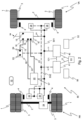
- Fig. 1 shows a schematic diagram of a preferred embodiment of an electrical equipment according to the invention, with an electropneumatic Service brake device 80, where pneumatic connections are shown and Fig. 2 a schematic diagram of the electrical equipment of Fig. 1 , showing electrical connections and some pneumatic connections.
- the following description of the electrical equipment refers to both figures.
- a front axle (VA) and a rear axle (RA) are shown, each having wheels 1 rotatably mounted on an axle 2.
- Each wheel 1 is assigned a pneumatic wheel brake actuator 4, which in the example shown is designed as a pneumatic service brake cylinder.
- Such a pneumatic wheel brake actuator 4 is arranged on each wheel 1 and, for example, actuates a disc brake 3 to generate a braking force.
- the pneumatic wheel brake actuator 4 is subjected to a brake pressure p VA or p HA , which creates a frictional force in the disc brake 3, resulting in a braking torque.
- speed sensors are provided on the wheels 1 to detect the speeds of individual wheels 1 and process them in higher-level functions such as ABS, ASR, or ESP.
- the electropneumatic service brake device 80 has a compressed air reservoir 10, which supplies various components 18, 20, 24, 82 of the electropneumatic service brake device 80 with compressed air via supply lines 14, 14a, 14b, 14c.
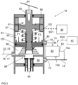
- a component represents a Fig. 3 schematically shown electropneumatic service brake valve device 18 here for example in the form of a foot brake module, which is connected to the supply line 14 via a supply inlet 15.
- the service brake valve device 18 is supplied with compressed air via this.
- the service brake valve device 18 further has a pneumatic control inlet 19, via which it can receive a pneumatic control pressure p St , with which the service brake valve device 18 is then pneumatically controlled.
- the service brake valve device 18 has two pneumatic control outputs 16, 17, via which it can output a first pneumatic brake control pressure p 1 and/or a second pneumatic brake control pressure p 2 into pneumatic control lines 22, 23.
- the service brake valve device 18 has a service brake actuating element 94, such as a brake pedal, via which braking requests from a driver can be input.
- the service brake valve device 18 is designed to transmit a braking request from the driver via a Fig. 3 shown, in particular electrical and contactless operating brake value transmitter 86 within its electrical channel and to control it as an actuation-dependent electrical actuation signal BS into a primary control connection SV1, as in Fig. 2 is shown.
- the electrical actuation signal BS is then fed via the primary control connection SV1 into a primary electronic brake control device 40, which here is formed, for example, by the electronic EBS control unit.
- the service brake valve device 18 has a housing in which a tappet piston 91 is axially movably received with a tappet receptacle 92 projecting through a cover opening of a housing cover.
- a tappet (not shown here) projects from above into the tappet receptacle 92 and is connected to the service brake actuating member 94, here, for example, in the form of a foot brake plate. Therefore, when the driver actuates the service brake actuating member 94, the tappet presses into the tappet receptacle 92 and the tappet piston 91 is moved by the actuating force into Fig. 3 moved downwards, like as illustrated by the arrow.
- the plunger piston 91 transmits the actuating force to a control piston 85, which is also axially movably mounted in the housing 2, preferably via a plunger piston compression spring 102.
- control piston 85 is mechanically connected to the tappet piston 91 via a tappet piston rod 87, wherein the tappet piston rod 87 is connected to the tappet piston 91 and can axially abut in an end of the control piston 85 designed as a cup-shaped sleeve 103 when the tappet piston rod 87 has reached the bottom of the sleeve 103, e.g., when the tappet piston 91 is moved toward the control piston 85 as a result of actuation of the service brake actuating element 94.
- the tappet piston rod 87 can slide in the sleeve 103 when the tappet piston 91 is moved away from the control piston 85.
- an outlet seat of a double-seat valve 88 is formed on a piston rod of the control piston 85.
- This outlet seat seals against a cup-shaped, hollow valve body of the double-seat valve 88, which is mounted axially movably in the housing, or lifts off from it, opening a flow cross-section between a working chamber 98 and a head-side through-opening in the valve body, which leads to a vent connection 99.
- the working chamber 98 is connected to the control outputs 16, 17, and these are connected to the control lines 22, 23, which in turn are connected to the pneumatic control inputs 95, 96 of a pressure control module 20.
- the control outputs 16, 17 are placed in one connection in the drawing; in reality, however, two separate control outputs 16, 17 are present.
- the valve body is urged against an inlet seat of the double-seat valve 88 by a valve body compression spring supported on the bottom of the housing and on the interior of the valve body.
- the inlet seat is formed on a radially inner edge of a central through-bore in another inner wall of the housing.
- Fig. 3 The "drive" position of the service brake valve device 18 is shown, in which the outlet seat is lifted from the valve body and the control outputs 16, 17 and thus also the wheel brake actuators 4 connected thereto are connected to the vent connection 99. This releases the active pneumatic wheel brake actuators 4.
- the pressure control module 20 includes an inlet-outlet solenoid valve combination controlled by an integrated electronic pressure control module control unit, which is connected on the output side to the pneumatic control input of the relay valve. Therefore, the relay valve can be actuated either by the pneumatic brake control pressure controlled through the de-energized backup valve or by the pneumatic brake control pressure generated electrically by controlling the inlet-outlet solenoid valve combination using the integrated electronic pressure control module control unit.
- the pressure control module control unit is connected via an electrical control input 97 to the primary control connection SV1, to which the primary electronic brake control device 40 is also connected, whereby the pressure control module control unit can be controlled or supplied with control signals by the primary electronic brake control device 40.
- the routines of the driver assistance system 93 could also be implemented in the primary electronic brake control device 40 and/or in the secondary electronic brake control device 41.
- the first and second brake control pressures p1 and p2 present at the control outputs 16, 17 and fed into the pneumatic control inputs 95, 96 of the pressure control module 20 via the control lines 22, 23 are applied to the then energized and consequently closed backup valves in the pressure control module 20 and not passed on to the integrated relay valves.
- the driver does not make a braking request and therefore does not actuate the service brake actuating element 94, but the driver assistance system 93 sends an assistance braking request signal AS to both the primary electronic brake control device 40 and the secondary electronic brake control device 41, as in Fig. 2 is indicated.
- the primary electronic brake control unit 40 can generate a first electrical brake request signal S1 based on the assistance brake request signal AS, which is then converted into corresponding brake pressures P VA , p HA , and p Trailer in the electrical service brake circuit, as described above, by the pressure control module 20 and the brake control module 24. Consequently, the assistance brake request signal AS is then implemented by the intact electrical service brake circuit or the intact pressure control module 20.
- the secondary electronic brake control device 41 In parallel or simultaneously, the secondary electronic brake control device 41 generates the second electrical brake request signal S2 based on the assistance brake request signal AS. This signal is fed via the secondary control connection SV2 into the solenoid valve device 82, which is then placed in the ventilation position and thereby generates the pneumatic control pressure p St , which is applied to the control chamber 90.
- the control pressure p St then prevailing in the control chamber 90 acts on the tappet piston 91 that delimits it and thus on the service brake actuating element 94, which the driver can feel on their foot when they touch the service brake actuating element 94 (pedal reaction). The driver can thus feel the initiation of automatic braking on their foot.
- the second actuating force F2 which preferably acts on the control piston 85 in parallel and in the same direction with respect to the first actuating force F1, As described above for the first actuating force F1, this ensures the generation of the first and second pneumatic brake control pressures p1, p2, which are fed into the pressure control module 20 at the control outputs 16, 17 and via the control lines 22, 23.
- first and second pneumatic brake control pressures p1, p2 are held back by the backup valves, which are energized by the primary electronic brake control device 40 and thus kept closed, and are therefore (initially) ineffective.
- the first and second pneumatic brake control pressures p1, p2 can immediately become effective in the pressure control module 20 at the integrated relay valves if the backup valves are de-energized and thus open due to a defect in the electrical service brake circuit.
- braking is to be carried out in response to both a driver braking request and an automatically generated braking request, for example if the driver brakes due to an emergency braking situation, but the braking request of the driver assistance system, e.g. in the form of an emergency braking assistant or an autopilot device, is greater than the driver's braking request.
- the first actuating force F1 from the driver's brake request and the second actuating force F2 from the automatically generated brake request act on the control piston 85 of the service brake valve device 18 in the same direction and in parallel, whereby the actuating forces F1, F2 on the control piston 85 add up and then the first pneumatic brake control pressure p1 and the second pneumatic brake control pressure p2 are output at the control outputs 16, 17 via the control lines 22, 23 into the pneumatic control inputs 95, 96 of the pressure control module 20, but are held back there by the backup valves powered by the primary electronic brake control device 40.
- the two backup valves integrated in the pressure control module 20 are de-energized and thereby switch to their open position, whereby in the event of a braking request from the driver assistance system 93, ie after the second electrical braking request signal S2 has been generated, the first and second brake control pressures p1, p2 already present there can control the relevant integrated relay valve, whereby the braking pressure p VA for the front axle VA and the braking pressure p HA for the rear axle HA can be generated. Since, for example, the brake pressure p VA for the front axle is used as the pneumatic control pressure for the trailer control module 24, the trailer brake pressure p trailer can also be generated so that a trailer that may be coupled can also be braked.
- the first and second pneumatic brake control pressures p1 and p2 can no longer be generated electrically, so that autonomous or automatic braking operation by the driver assistance system 93 is no longer possible.
- the pneumatic service brake circuit can then only be controlled by braking requests from the driver and the then mechanically generated first and second pneumatic brake control pressures p1 and p2. Since the backup valves in the pressure control module 20 are then de-energized and consequently switched to their through position, the first and second pneumatic brake control pressures p1 and p2 in the pressure control module 20 generate the brake pressure p VA for the front axle and the brake pressure p HA for the rear axle HA. Since the brake pressure p VA for the front axle VA is preferably used as the pneumatic control pressure for the trailer control module 24, the trailer brake pressure p trailer can also be generated, so that any trailer coupled to the vehicle can also be braked.
- the electropneumatic service brake device 80 and in particular the secondary electronic brake control device 41 (by appropriate programming), the solenoid valve device 82 and the service brake valve device 18 are designed such that the first and second pneumatic brake control pressures p1 and p2 are applied to, for example, each automatically generated assistance braking request signal AS, which represents an autonomous or automatic braking request, and is then immediately and directly present at the electromagnetic backup valve of the pressure control module 20, which is (still) closed by current supply.
- the first pneumatic brake control pressure p1 and the second pneumatic brake control pressure p2 are always present in the pressure control module 20 and can therefore ensure that the brake pressures p VA , p HA and p trailer are generated immediately after the failure of the electrical service brake circuit.
- the pneumatic control pressure p St and/or the first and second pneumatic brake control pressures p1 and p2 are preferably only generated electrically when the magnitude of the automatic or autonomous braking request represented by the assistance braking request signal AS is greater than the magnitude of a limit braking request a grenz .
- This limitation can be implemented, for example, by appropriate programming of the secondary electronic brake control device 41.
- the limit braking request a limit is preferably a deceleration other than zero or represents such a deceleration, for example -3 m/s 2 . Therefore, if, for example, an automatic or autonomous braking request (deceleration) of -4 m/s 2 is requested, first and second pneumatic brake control pressures p1 and p2 would be generated electrically, but not for an automatic or autonomous braking request (deceleration) of only -2 m/s 2 .
- the solenoid valve device 82 is therefore controlled by the secondary electronic brake control device 41, which is powered by the electrical secondary supply source 58, for example, in such a way that, independently of and in particular before the ignition or start signal for the drive engine of the vehicle is generated, the two pneumatic brake control pressures p1, p2 are generated and fed into the two pneumatic Control inputs of the pressure control module 20 are controlled. Since the starter is not supplied with power from the secondary supply source 58, the secondary supply source 58 is not involved in the power supply of the starter, so that no voltage drop occurs when the drive motor is started.
Landscapes
- Engineering & Computer Science (AREA)
- Transportation (AREA)
- Mechanical Engineering (AREA)
- Regulating Braking Force (AREA)
- Braking Systems And Boosters (AREA)
Claims (24)
- Équipement électropneumatique d'un véhicule avec une machine d'entraînement pouvant être mise en service par un signal d'allumage ou de démarrage, comprenant un appareil de freinage de service électropneumatique (80), dans lequel l'appareil de freinage de service électropneumatique (80) présente au moins :a) des actionneurs pneumatiques de freinage de roue (4),b) au moins un circuit électrique de freinage de service,c) au moins un circuit pneumatique de freinage de service,d) un appareil d'entrée de freinage de service (18) au moins électrique qui génère un signal d'actionnement électrique (BS) à l'intérieur de l'au moins un circuit électrique de freinage de service,e) à l'intérieur du circuit électrique de freinage de service, un appareil de commande de freinage électronique primaire (40), qui, en fonction du signal d'actionnement électrique (BS), génère un premier signal électrique de demande de freinage (S1) représentant une pression de freinage de consigne,f) un appareil de commande de freinage électronique secondaire (41) qui commande au moins un actionneur (18, 82) actionné électriquement par un second signal électrique de demande de freinage (S2), qui est conçu pour générer au moins une pression pneumatique de commande de freinage (p1, p2) sur la base du second signal électrique de demande de freinage (S2),g) au moins un module régulateur de pression électropneumatique (20) avec un dispositif de commande électronique intégré en tant qu'élément de l'au moins un circuit électrique de freinage de service, dans lequel le au moins un module régulateur de pression électropneumatique (20) est conçug1) pour recevoir au niveau d'une entrée de commande électrique (97) du module régulateur de pression (20) le premier signal électrique de demande de freinage (S1) et, en fonction du premier signal électrique de demande de freinage (S1), générer à l'intérieur de l'au moins un circuit électrique de freinage de service une pression de freinage régulée électroniquement (pVA, pHA, premorque) pour les actionneurs de freinage de roue (3, 4), etg2) pour recevoir au niveau d'au moins une entrée de commande pneumatique (95, 96) du module régulateur de pression (20) la au moins une pression pneumatique de commande de freinage (p1, p2) et, en fonction de la au moins une pression pneumatique de commande de freinage (p1, p2) à l'intérieur de l'au moins un circuit pneumatique de freinage de service, une pression de freinage (pvA, pHA, premorque) pour les actionneurs de freinage de roue (3, 4), etg3) pour générer la pression de freinage (pVA, pHA, premorque) dans les actionneurs pneumatiques de freinage de roue (3, 4),g4) le au moins un module régulateur de pression électropneumatique (20) présente au moins une soupape de secours électromagnétique qui est connectée à l'entrée de commande pneumatique (95, 96) et qui est conçue et commandée de manière àg4a) contenir la au moins une pression pneumatique de commande de freinage (p1, p2) lorsque le au moins un circuit électrique de freinage de service est intact ou suffisamment alimenté, maisg4b) dans le cas contraire, lorsque le au moins un circuit électrique de freinage de service présente un défaut ou est insuffisamment alimenté, transmettre la au moins une pression pneumatique de commande de freinage (p1, p2) pour que le au moins un module régulateur de pression (20) génère la pression de freinage (pVA, pHA premorque) en fonction de la au moins une pression pneumatique de commande de freinage (p1, p2), caractérisé en ce queh) le au moins un actionneur (18, 82) actionné électriquement est commandé par l'appareil de commande de freinage électronique secondaire (41) en fonction d'un signal de demande de freinage d'assistance (AS) généré automatiquement par un système d'aide à la conduite (93) et/ou en fonction du signal d'actionnement électrique (BS) de sorte que, indépendamment d'un défaut du circuit électrique de freinage de service, la au moins une pression pneumatique de commande de freinage (p1, p2) est générée par l'actionneur (18, 82) actionné électriquement en réponse au signal de demande de freinage d'assistance (AS) et/ou au signal d'actionnement de freinage (BS) et est injectée dans la au moins une entrée de commande pneumatique (95, 96) de l'au moins un module régulateur de pression (20), et/ou dans lequeli) le au moins un actionneur (18, 82) actionné électriquement est commandé par l'appareil de commande de freinage électronique secondaire (41) de sorte que, indépendamment d'une génération du signal d'allumage ou de démarrage pour la machine d'entraînement du véhicule, la au moins une pression pneumatique de commande de freinage (p1, p2) est générée par le au moins un actionneur (18, 82) actionné électriquement et est injectée dans la au moins une entrée de commande pneumatique (95, 96) de l'au moins un module régulateur de pression (20).
- Équipement électropneumatique selon la revendication 1, caractérisé en ce que le au moins un actionneur (18, 82) est commandé par l'appareil de commande de freinage électronique secondaire (41) de sorte que, en réponse à chaque signal de demande de freinage d'assistance (AS) et/ou à chaque signal d'actionnement de freinage (BS) qui représente une demande de freinage dont la valeur est supérieure à la valeur d'une demande de freinage limite (alimite), la au moins une pression pneumatique de commande de freinage (p1, p2) est générée et injectée dans la au moins une entrée de commande pneumatique (95, 96) du module régulateur de pression (20).
- Équipement électropneumatique selon la revendication 2, caractérisé en ce que la demande de freinage limite (alimite) est nulle ou représente un ralentissement différent de nul.
- Équipement électropneumatique selon l'une quelconque des revendications précédentes, caractérisé en ce que l'appareil d'entrée de freinage de service (18)a) est un appareil d'entrée de freinage de service (18) purement électrique qui génère uniquement le signal d'actionnement électrique (BS), mais aucune pression pneumatique de commande de freinage, oub) est un appareil de soupape de freinage de service électropneumatique qui génère, en plus du canal électrique, dans au moins un canal pneumatique, la au moins une pression pneumatique de commande de freinage (p1, p2).
- Équipement électropneumatique selon la revendication 4, caractérisé en ce que l'appareil de soupape de freinage de service électropneumatique (18) est conçu en ce que, par un actionnement d'un organe d'actionnement de freinage de service (94) en raison d'une demande de freinage du conducteur, au moins un piston de commande (85) de l'appareil de soupape de freinage de service (18) est chargé avec une première force d'actionnement (F1), et le piston de commande (85) commande directement ou indirectement au moins une soupape double siège (88) contenant un siège d'entrée et un siège de sortie de l'appareil de soupape de freinage de service (18) pour générer la au moins une pression pneumatique de commande de freinage (p1, p2).
- Équipement électropneumatique selon la revendication 5, caractérisé en ce que le au moins un actionneur (18, 82) actionné électriquement comprend l'appareil de soupape de freinage de service (18) ainsi que des moyens de génération d'une seconde force d'actionnement (F2) qui, par rapport à la première force d'actionnement (F1), agit parallèlement et dans le même sens ou en sens inverse sur le au moins un piston de commande (85) de l'appareil de soupape de freinage de service (18).
- Équipement électropneumatique selon la revendication 6, caractérisé en ce que les moyens de génération de la seconde force d'actionnement (F2) contiennent un générateur de force (82) à commande électrique, en particulier électrique, électrohydraulique ou électropneumatique.
- Équipement électropneumatique selon la revendication 7, caractérisé en ce que le générateur de force électropneumatique (82) comprend un appareil de soupape magnétique alimenté par une réserve d'air comprimé (10) avec de l'air comprimé de réserve sous pression de réserve (10), appareil qui génère, sur la base de l'air comprimé de réserve, une pression de commande pneumatique (pSt) au niveau du piston de commande (85) de l'appareil de soupape de freinage de service (18), pression sur laquelle la seconde force d'actionnement (F2) est basée.
- Équipement électropneumatique selon l'une quelconque des revendications 5 à 8, caractérisé en ce que l'appareil de soupape de freinage de service électropneumatique (18) est conçu pour générer, de manière séparée par circuit, une première pression pneumatique de commande de freinage (p1) pour un premier circuit pneumatique de freinage de service et une seconde pression pneumatique de commande de freinage (p2) pour un second circuit pneumatique de freinage de service.
- Équipement électropneumatique selon l'une quelconque des revendications précédentes, caractérisé en ce que l'appareil de freinage de service électropneumatique (80) comprend au moins un premier circuit de freinage pour un premier essieu (VA) du véhicule et au moins un second circuit de freinage pour un second essieu (HA) du véhicule, dans lequel il est conçu pour qu'une première pression de freinage (pVA) pour le premier circuit de freinage et une seconde pression de freinage (pHA) pour le second circuit de freinage sont générées individuellement, dans lequel le module régulateur de pression (20) est conçu en tant que module régulateur de pression à 2 canaux et génère la première pression de freinage (pVA) sur la base de la première pression pneumatique de commande de freinage (p1) et la seconde pression de freinage (pHA) sur la base de la seconde pression pneumatique de commande de freinage (p2).
- Équipement électropneumatique selon la revendication 9 ou 10, caractérisé en ce que l'appareil de freinage de service électropneumatique (80) comprend un module de commande de remorque (24) qui est conçu en tant que module régulateur de pression et qui est commandé électriquement au niveau de son entrée de commande électrique par l'intermédiaire du premier signal électrique de demande de freinage (S1) et qui est commandé pneumatiquement au niveau de son entrée de commande pneumatique par l'intermédiaire de la première pression de freinage (pVA) ou de la seconde pression de freinage (pHA).
- Équipement électropneumatique selon l'une quelconque des revendications précédentes, caractérisé en ce que l'appareil de commande de freinage électronique primaire (40), le dispositif de commande électronique intégré de l'au moins un module régulateur de pression (20) et le transmetteur de valeur de freinage (86) de l'appareil d'entrée de freinage de service (18) sont raccordés à une connexion de commande primaire (SV1) qui est séparée et indépendante d'une connexion de commande secondaire (SV2) à laquelle l'appareil de commande de freinage électronique secondaire (41) et le au moins un actionneur (18, 82) actionné électriquement sont raccordés.
- Équipement électropneumatique selon l'une quelconque des revendications précédentes, caractérisé en ce que le système d'assistance à la conduite(93) comprend un appareil de pilotage automatique, un assistant de freinage d'urgence ou un dispositif de régulation de dynamique de conduite (ESP).
- Équipement électropneumatique selon l'une quelconque des revendications précédentes, caractérisé en ce que l'appareil de commande de freinage électronique secondaire (41) commande le au moins un actionneur (18, 82) actionné électriquement de sorte que la au moins une pression pneumatique de commande de freinage (p1, p2) est générée en fonction d'au moins les grandeurs suivantes et injectée dans la au moins une entrée de commande pneumatique (95, 96) du module régulateur de pression (20) :a) un rapport de masse entre le véhicule et la remorque,b) les charges d'essieu d'au moins deux essieux (VA, HA) du véhicule,c) un certain nombre de canaux pneumatiques de l'appareil de soupape de freinage de service (18).
- Équipement électropneumatique selon l'une quelconque des revendications précédentes, caractérisé en ce que l'appareil de commande de freinage électronique primaire (40) génère le premier signal électrique de demande de freinage (S1) en fonction du signal d'actionnement électrique (BS) et/ou en fonction du signal de demande de freinage d'assistance (AS).
- Équipement électropneumatique selon l'une quelconque des revendications précédentes, caractérisé en ce que des soupapes de commande de pression (28) pouvant être commandées électriquement par l'appareil de commande de freinage électronique primaire (40) et/ou par l'appareil de commande de freinage électronique secondaire (40) sont prévues, par l'intermédiaire desquelles la pression de freinage (pvA, PHA) peut être commandée individuellement dans un actionneur pneumatique de freinage de roue (4).
- Équipement électropneumatique selon l'une quelconque des revendications précédentes, caractérisé en ce quea) un fonctionnement normal est prévu, dans lequel une commande/régulation du circuit électrique de freinage de service est effectuée en particulier exclusivement par l'intermédiaire de l'appareil de commande de freinage primaire (40), et/ou en ce queb) un premier niveau de redondance est prévu, dans lequel une commande de l'au moins un circuit pneumatique de freinage de service est effectuée par l'intermédiaire de la au moins une pression pneumatique de commande de freinage (p1, p2) générée par l'actionneur (18, 82) actionné électriquement, et/ou en ce quec) un second niveau de redondance est prévu, dans lequel une commande pneumatique de l'au moins un circuit pneumatique de freinage de service est effectuée en particulier exclusivement par l'intermédiaire de la au moins une pression pneumatique de commande de freinage (p1, p2) générée par un actionnement d'un organe d'actionnement de freinage de service (94).
- Équipement électropneumatique selon l'une quelconque des revendications précédentes, caractérisé en ce que, à l'intérieur du circuit électrique de freinage de service, une source d'alimentation primaire électrique (52) est prévue, qui alimente en énergie électrique l'appareil de commande de freinage électronique primaire (40).
- Équipement électropneumatique selon la revendication 18, caractérisé en ce que la source d'alimentation primaire électrique (52) est indépendante d'une source d'alimentation secondaire (58) qui alimente en énergie électrique l'appareil de commande de freinage électronique secondaire (41).
- Équipement électropneumatique selon les revendications 7 et 19, caractérisé en ce que la source d'alimentation secondaire (58) alimente en énergie électrique au moins une partie du générateur de force (82).
- Équipement électropneumatique selon l'une quelconque des revendications précédentes, caractérisé en ce que l'appareil d'entrée de freinage de service (18) présente un organe d'actionnement de freinage de service (94) et, à l'intérieur de l'au moins un circuit électrique de freinage de service, au moins un canal électrique avec au moins un générateur de valeur de freinage électrique (86) pouvant être actionné par l'organe d'actionnement de freinage de service (94), générateur qui génère le signal d'actionnement électrique (BS) en fonction d'un actionnement de l'organe d'actionnement de freinage de service (94).
- Équipement électropneumatique selon l'une quelconque des revendications précédentes, caractérisé en ce que l'appareil de commande de freinage électronique secondaire (41) commande, en fonction d'un signal de demande de freinage d'assistance (AS) généré automatiquement par un système d'assistance à la conduite (93) et/ou en fonction du signal d'actionnement électrique (BS) et/ou indépendamment du signal d'allumage ou de démarrage, le au moins un actionneur (18, 82) actionné électriquement par l'intermédiaire du second signal électrique de demande de freinage (S2).
- Véhicule avec une machine d'entraînement pouvant être mise en service par un signal d'allumage ou de démarrage, comprenant un équipement électropneumatique selon l'une quelconque des revendications précédentes.
- Véhicule selon la revendication 23, caractérisé en ce qu'il est conçu en tant que véhicule tracteur pour tirer une remorque freinée.
Applications Claiming Priority (2)
| Application Number | Priority Date | Filing Date | Title |
|---|---|---|---|
| DE102021114055.2A DE102021114055A1 (de) | 2021-05-31 | 2021-05-31 | Elektro-pneumatische Ausrüstung eines Fahrzeugs mit vorsorglich mit Backup-Druck versorgtem autonomen Bremskreis |
| PCT/EP2022/063727 WO2022253594A1 (fr) | 2021-05-31 | 2022-05-20 | Équipement électropneumatique d'un véhicule comprenant un système de freinage autonome alimenté par précaution avec une pression de secours |
Publications (2)
| Publication Number | Publication Date |
|---|---|
| EP4347336A1 EP4347336A1 (fr) | 2024-04-10 |
| EP4347336B1 true EP4347336B1 (fr) | 2025-07-09 |
Family
ID=82021140
Family Applications (1)
| Application Number | Title | Priority Date | Filing Date |
|---|---|---|---|
| EP22730178.5A Active EP4347336B1 (fr) | 2021-05-31 | 2022-05-20 | Équipement électropneumatique d'un véhicule comprenant un système de freinage autonome alimenté par précaution avec une pression de secours |
Country Status (5)
| Country | Link |
|---|---|
| US (1) | US12509036B2 (fr) |
| EP (1) | EP4347336B1 (fr) |
| CN (1) | CN117396383A (fr) |
| DE (1) | DE102021114055A1 (fr) |
| WO (1) | WO2022253594A1 (fr) |
Families Citing this family (2)
| Publication number | Priority date | Publication date | Assignee | Title |
|---|---|---|---|---|
| DE102022118023A1 (de) | 2022-07-19 | 2024-01-25 | Knorr-Bremse Systeme für Nutzfahrzeuge GmbH | Ausrüstung eines teilautonom oder autonom betriebenen Kraftfahrzeugs |
| US12540682B2 (en) * | 2023-04-14 | 2026-02-03 | Bendix Commercial Vehicle Systems Llc | Foot brake module with a guiding feature on a relay piston |
Citations (15)
| Publication number | Priority date | Publication date | Assignee | Title |
|---|---|---|---|---|
| EP1541437A2 (fr) | 2003-12-09 | 2005-06-15 | KNORR-BREMSE SYSTEME FÜR NUTZFAHRZEUGE GmbH | Système de freinage électronique pour véhicule |
| EP1343674B1 (fr) | 2000-12-08 | 2008-08-13 | KNORR-BREMSE SYSTEME FÜR NUTZFAHRZEUGE GmbH | Module de frein a pied a fonction d'activation |
| DE102014112015A1 (de) * | 2014-08-22 | 2016-02-25 | Knorr-Bremse Systeme für Nutzfahrzeuge GmbH | Verfahren zum Steuern einer durch eine Betriebsbremsventileinrichtung betätigten Betriebsbremseinrichtung sowie Betriebsbremseinrichtung |
| DE102016215697A1 (de) | 2016-08-22 | 2018-02-22 | Robert Bosch Gmbh | Bypass-Einheit und pneumatisches Bremssystem für ein Fahrzeug |
| EP3197735B1 (fr) | 2014-09-22 | 2018-11-21 | KNORR-BREMSE Systeme für Nutzfahrzeuge GmbH | Équipement électrique d'un véhicule, présentant un dispositif de freinage et de direction au moins partiellement électrique, doté d'une disponibilité élevée |
| DE102017113336A1 (de) | 2017-06-19 | 2018-12-20 | Knorr-Bremse Systeme für Nutzfahrzeuge GmbH | Elektrische Ausrüstung eines Fahrzeugs oder einer Fahrzeugkombination aus einem Zugfahrzeug und wenigstens einem Anhängerfahrzeug |
| DE102017121761A1 (de) | 2017-09-20 | 2019-03-21 | Knorr-Bremse Systeme für Nutzfahrzeuge GmbH | Elektropneumatisches Bremssystem mit Testmodus für den pneumatischen Backup-Bremskreis |
| WO2019076861A1 (fr) | 2017-10-16 | 2019-04-25 | Knorr-Bremse Systeme für Nutzfahrzeuge GmbH | Concept de redondance pour un système de freinage, destiné à une conduite hautement automatisée |
| DE102017011611A1 (de) | 2017-12-15 | 2019-06-19 | Knorr-Bremse Systeme für Nutzfahrzeuge GmbH | Elektrische Ausrüstung eines Fahrzeugs mit redundanter ABS- und Fahrerdynamikregelung |
| WO2019210964A1 (fr) | 2018-05-03 | 2019-11-07 | Volvo Truck Corporation | Commande de mouvement redondant pour véhicule doté d'un agencement de freinage redondant |
| DE102018219378A1 (de) | 2018-11-13 | 2020-05-14 | Knorr-Bremse Systeme für Nutzfahrzeuge GmbH | Redundantes Bremssystem und Verfahren zum Betrieb eines solchen Bremssystems |
| DE102019106591A1 (de) | 2019-03-15 | 2020-09-17 | Wabco Gmbh | Elektronisch steuerbares Bremssystem mit zwei Rückfallebenen |
| EP3515776B1 (fr) | 2016-09-21 | 2020-10-14 | KNORR-BREMSE Systeme für Nutzfahrzeuge GmbH | Unité de conditionnement d'air pour un dispositif de freinage d'un véhicule utilitaire et procédé pour faire fonctionner une unité de conditionnement d'air |
| WO2021110640A1 (fr) | 2019-12-04 | 2021-06-10 | Zf Cv Systems Global Gmbh | Système de frein pneumatique à commande électrique comprenant un système de modulateur de pression à deux canaux |
| WO2021190869A1 (fr) | 2020-03-24 | 2021-09-30 | Knorr-Bremse Systeme für Nutzfahrzeuge GmbH | Système de frein à commande électronique présentant une pression de commande de secours générée sur la base d'un circuit consommateur d'air comprimé supplémentaire |
Family Cites Families (9)
| Publication number | Priority date | Publication date | Assignee | Title |
|---|---|---|---|---|
| DE102008009043B3 (de) | 2008-02-14 | 2009-05-14 | Knorr-Bremse Systeme für Nutzfahrzeuge GmbH | Elektronisch geregeltes Bremssystem mit redundanter Steuerung der Bremsaktuatoren |
| DE102015016720A1 (de) | 2015-12-22 | 2017-06-22 | Wabco Gmbh | Verfahren zum adaptiven Regeln einer fahrerbetätigungsabhängigen Fahrzeug-Ist-Verzögerung |
| DE102016010463A1 (de) * | 2016-08-31 | 2018-03-01 | Wabco Gmbh | Verfahren zum elektronischen Steuern eines pneumatischen Bremssystems in einem Fahrzeug, insbesondere Nutzfahrzeug, sowie elektronisch steuerbares pneumatisches Bremssystem |
| DE102017002716A1 (de) | 2017-03-21 | 2018-09-27 | Wabco Gmbh | Elektronisch steuerbares Bremssystem sowie Verfahren zum Steuern des elektronisch steuerbaren Bremssystems |
| DE102017002721A1 (de) | 2017-03-21 | 2018-09-27 | Wabco Gmbh | Elektronisch steuerbares Bremssystem sowie Verfahren zum Steuern des elektronisch steuerbaren Bremssystems mit rein elektrischem Bremswertgeber |
| DE102017113743A1 (de) * | 2017-06-21 | 2018-12-27 | Man Truck & Bus Ag | Druckmittelbetätigte und zumindest teilweise elektronische Bremsvorrichtung |
| DE102019106274A1 (de) | 2019-03-12 | 2020-09-17 | Wabco Gmbh | Elektronisch steuerbares Bremssystem mit zwei Rückfallebenen (alternative Ausführung) |
| DE102019131110A1 (de) | 2019-11-18 | 2021-05-20 | Wabco Europe Bvba | Bremssystem mit sicherer Notstoppfunktion und Verfahren hierzu |
| WO2021099307A1 (fr) | 2019-11-18 | 2021-05-27 | Zf Cv Systems Global Gmbh | Unité de soupape à sécurité intégrée, système de freinage pneumatique à commande électronique, procédé d'actionnement d'un système de freinage |
-
2021
- 2021-05-31 DE DE102021114055.2A patent/DE102021114055A1/de active Pending
-
2022
- 2022-05-20 US US18/559,603 patent/US12509036B2/en active Active
- 2022-05-20 CN CN202280039079.1A patent/CN117396383A/zh active Pending
- 2022-05-20 WO PCT/EP2022/063727 patent/WO2022253594A1/fr not_active Ceased
- 2022-05-20 EP EP22730178.5A patent/EP4347336B1/fr active Active
Patent Citations (15)
| Publication number | Priority date | Publication date | Assignee | Title |
|---|---|---|---|---|
| EP1343674B1 (fr) | 2000-12-08 | 2008-08-13 | KNORR-BREMSE SYSTEME FÜR NUTZFAHRZEUGE GmbH | Module de frein a pied a fonction d'activation |
| EP1541437A2 (fr) | 2003-12-09 | 2005-06-15 | KNORR-BREMSE SYSTEME FÜR NUTZFAHRZEUGE GmbH | Système de freinage électronique pour véhicule |
| DE102014112015A1 (de) * | 2014-08-22 | 2016-02-25 | Knorr-Bremse Systeme für Nutzfahrzeuge GmbH | Verfahren zum Steuern einer durch eine Betriebsbremsventileinrichtung betätigten Betriebsbremseinrichtung sowie Betriebsbremseinrichtung |
| EP3197735B1 (fr) | 2014-09-22 | 2018-11-21 | KNORR-BREMSE Systeme für Nutzfahrzeuge GmbH | Équipement électrique d'un véhicule, présentant un dispositif de freinage et de direction au moins partiellement électrique, doté d'une disponibilité élevée |
| DE102016215697A1 (de) | 2016-08-22 | 2018-02-22 | Robert Bosch Gmbh | Bypass-Einheit und pneumatisches Bremssystem für ein Fahrzeug |
| EP3515776B1 (fr) | 2016-09-21 | 2020-10-14 | KNORR-BREMSE Systeme für Nutzfahrzeuge GmbH | Unité de conditionnement d'air pour un dispositif de freinage d'un véhicule utilitaire et procédé pour faire fonctionner une unité de conditionnement d'air |
| DE102017113336A1 (de) | 2017-06-19 | 2018-12-20 | Knorr-Bremse Systeme für Nutzfahrzeuge GmbH | Elektrische Ausrüstung eines Fahrzeugs oder einer Fahrzeugkombination aus einem Zugfahrzeug und wenigstens einem Anhängerfahrzeug |
| DE102017121761A1 (de) | 2017-09-20 | 2019-03-21 | Knorr-Bremse Systeme für Nutzfahrzeuge GmbH | Elektropneumatisches Bremssystem mit Testmodus für den pneumatischen Backup-Bremskreis |
| WO2019076861A1 (fr) | 2017-10-16 | 2019-04-25 | Knorr-Bremse Systeme für Nutzfahrzeuge GmbH | Concept de redondance pour un système de freinage, destiné à une conduite hautement automatisée |
| DE102017011611A1 (de) | 2017-12-15 | 2019-06-19 | Knorr-Bremse Systeme für Nutzfahrzeuge GmbH | Elektrische Ausrüstung eines Fahrzeugs mit redundanter ABS- und Fahrerdynamikregelung |
| WO2019210964A1 (fr) | 2018-05-03 | 2019-11-07 | Volvo Truck Corporation | Commande de mouvement redondant pour véhicule doté d'un agencement de freinage redondant |
| DE102018219378A1 (de) | 2018-11-13 | 2020-05-14 | Knorr-Bremse Systeme für Nutzfahrzeuge GmbH | Redundantes Bremssystem und Verfahren zum Betrieb eines solchen Bremssystems |
| DE102019106591A1 (de) | 2019-03-15 | 2020-09-17 | Wabco Gmbh | Elektronisch steuerbares Bremssystem mit zwei Rückfallebenen |
| WO2021110640A1 (fr) | 2019-12-04 | 2021-06-10 | Zf Cv Systems Global Gmbh | Système de frein pneumatique à commande électrique comprenant un système de modulateur de pression à deux canaux |
| WO2021190869A1 (fr) | 2020-03-24 | 2021-09-30 | Knorr-Bremse Systeme für Nutzfahrzeuge GmbH | Système de frein à commande électronique présentant une pression de commande de secours générée sur la base d'un circuit consommateur d'air comprimé supplémentaire |
Non-Patent Citations (3)
| Title |
|---|
| ANONYMOUS: "EBS für Motorwagen und Bussen Systembeschreibung, 3. Ausgabe ", WABCO EUROPE BVBA, 1 January 2016 (2016-01-01), pages 1 - 52, XP055948991 |
| ANONYMOUS: "EBS3 – ELEKTRONISCHES BREMSSYSTEM SYSTEMBESCHREIBUNG", WABCO STANDARD BROCHURE EBS3 – ELEKTRONISCHES BREMSSYSTEM - SYSTEMBESCHREIBUNG, WABCO STANDARD GMBH, HANNOVER, DE, 1 December 2016 (2016-12-01), Hannover, DE, pages 1 - 44, XP055949074 |
| D9 - ROBERT BOSCH GMBH: "Springer", 1 January 2018, article BOSCH, KRAFTFAHRTECHNISCHES TASCHENBUCH, 29. AUFLAGE: "Bremssysteme", pages: 1086 - 1125, XP093188444 |
Also Published As
| Publication number | Publication date |
|---|---|
| US12509036B2 (en) | 2025-12-30 |
| US20240425022A1 (en) | 2024-12-26 |
| CN117396383A (zh) | 2024-01-12 |
| DE102021114055A1 (de) | 2022-12-01 |
| EP4347336A1 (fr) | 2024-04-10 |
| WO2022253594A1 (fr) | 2022-12-08 |
Similar Documents
| Publication | Publication Date | Title |
|---|---|---|
| DE102014013756B3 (de) | Elektrische Ausrüstung eines Fahrzeugs mit einer wenigstens teilweise elektrischen Brems- und Lenkeinrichtung mit hoher Verfügbarkeit | |
| EP3642089B1 (fr) | Équipement électrique pour un véhicule ou une combinaison de véhicules comprenant un véhicule tracteur et au moins un véhicule tracté | |
| EP3529118B1 (fr) | Système comprenant des unités de commande séparées pour un frein de stationnement électrique | |
| EP3529117B1 (fr) | Système comprenant des unités de commande séparées pour les unités de réglage d'un frein de stationnement électrique | |
| EP3576995B1 (fr) | Équipement électrique d'un véhicule comprenant un dispositif de freinage et de direction au moins partiellement électrique | |
| EP3724043B1 (fr) | Équipement électrique d'un véhicule comprenant une régulation dynamique redondante de l'abs et de la dynamique de conduite | |
| EP3421309B1 (fr) | Dispositif de freinage actionné par un agent de pression et au moins partiellement électronique | |
| EP4069559B1 (fr) | Ensemble soupape de frein de stationnement monostable et insensible aux défaillances | |
| EP3183145B1 (fr) | Procédé de commande d'un dispositif de frein de service actionné par un dispositif de soupape de frein de service et dispositif de frein de service | |
| WO2019197555A1 (fr) | Système de freinage hydraulique de véhicule et procédé pour le faire fonctionner | |
| DE102012025423A1 (de) | Elektrohydraulische Fahrzeug-Bremsanlage und Verfahren zum Betreiben derselben | |
| EP4347336B1 (fr) | Équipement électropneumatique d'un véhicule comprenant un système de freinage autonome alimenté par précaution avec une pression de secours | |
| EP4370391A1 (fr) | Procédé de contrôle du fonctionnement d'un système de freinage électronique à fluide sous pression d'un véhicule | |
| WO2024094471A1 (fr) | Unité structurale électropneumatique et dispositif de frein électropneumatique à double redondance et commande de glissement de frein | |
| DE102023134202B3 (de) | Bremsanlage eines Fahrzeugs mit redundanter Parkbremsfunktion | |
| DE102022117667A1 (de) | Verfahren zum Bestimmen eines Bremsdrucks und druckmittelbetätigte Bremseinrichtung | |
| WO2024017608A1 (fr) | Équipement d'un véhicule à moteur fonctionnant de manière autonome ou partiellement autonome | |
| DE102024125055A1 (de) | Elektro-pneumatische Betriebsbremseinrichtung mit Rückkopplung des Betriebsbremsdrucks |
Legal Events
| Date | Code | Title | Description |
|---|---|---|---|
| STAA | Information on the status of an ep patent application or granted ep patent |
Free format text: STATUS: UNKNOWN |
|
| STAA | Information on the status of an ep patent application or granted ep patent |
Free format text: STATUS: THE INTERNATIONAL PUBLICATION HAS BEEN MADE |
|
| PUAI | Public reference made under article 153(3) epc to a published international application that has entered the european phase |
Free format text: ORIGINAL CODE: 0009012 |
|
| STAA | Information on the status of an ep patent application or granted ep patent |
Free format text: STATUS: REQUEST FOR EXAMINATION WAS MADE |
|
| 17P | Request for examination filed |
Effective date: 20240102 |
|
| AK | Designated contracting states |
Kind code of ref document: A1 Designated state(s): AL AT BE BG CH CY CZ DE DK EE ES FI FR GB GR HR HU IE IS IT LI LT LU LV MC MK MT NL NO PL PT RO RS SE SI SK SM TR |
|
| DAV | Request for validation of the european patent (deleted) | ||
| DAX | Request for extension of the european patent (deleted) | ||
| GRAP | Despatch of communication of intention to grant a patent |
Free format text: ORIGINAL CODE: EPIDOSNIGR1 |
|
| STAA | Information on the status of an ep patent application or granted ep patent |
Free format text: STATUS: GRANT OF PATENT IS INTENDED |
|
| INTG | Intention to grant announced |
Effective date: 20250203 |
|
| GRAS | Grant fee paid |
Free format text: ORIGINAL CODE: EPIDOSNIGR3 |
|
| P01 | Opt-out of the competence of the unified patent court (upc) registered |
Free format text: CASE NUMBER: APP_19331/2025 Effective date: 20250423 |
|
| GRAA | (expected) grant |
Free format text: ORIGINAL CODE: 0009210 |
|
| STAA | Information on the status of an ep patent application or granted ep patent |
Free format text: STATUS: THE PATENT HAS BEEN GRANTED |
|
| AK | Designated contracting states |
Kind code of ref document: B1 Designated state(s): AL AT BE BG CH CY CZ DE DK EE ES FI FR GB GR HR HU IE IS IT LI LT LU LV MC MK MT NL NO PL PT RO RS SE SI SK SM TR |
|
| REG | Reference to a national code |
Ref country code: GB Ref legal event code: FG4D Free format text: NOT ENGLISH |
|
| REG | Reference to a national code |
Ref country code: CH Ref legal event code: EP |
|
| REG | Reference to a national code |
Ref country code: IE Ref legal event code: FG4D Free format text: LANGUAGE OF EP DOCUMENT: GERMAN |
|
| REG | Reference to a national code |
Ref country code: DE Ref legal event code: R096 Ref document number: 502022004604 Country of ref document: DE |
|
| REG | Reference to a national code |
Ref country code: NL Ref legal event code: MP Effective date: 20250709 |
|
| PG25 | Lapsed in a contracting state [announced via postgrant information from national office to epo] |
Ref country code: PT Free format text: LAPSE BECAUSE OF FAILURE TO SUBMIT A TRANSLATION OF THE DESCRIPTION OR TO PAY THE FEE WITHIN THE PRESCRIBED TIME-LIMIT Effective date: 20251110 |
|
| PG25 | Lapsed in a contracting state [announced via postgrant information from national office to epo] |
Ref country code: NL Free format text: LAPSE BECAUSE OF FAILURE TO SUBMIT A TRANSLATION OF THE DESCRIPTION OR TO PAY THE FEE WITHIN THE PRESCRIBED TIME-LIMIT Effective date: 20250709 |
|
| PG25 | Lapsed in a contracting state [announced via postgrant information from national office to epo] |
Ref country code: IS Free format text: LAPSE BECAUSE OF FAILURE TO SUBMIT A TRANSLATION OF THE DESCRIPTION OR TO PAY THE FEE WITHIN THE PRESCRIBED TIME-LIMIT Effective date: 20251109 |
|
| PG25 | Lapsed in a contracting state [announced via postgrant information from national office to epo] |
Ref country code: NO Free format text: LAPSE BECAUSE OF FAILURE TO SUBMIT A TRANSLATION OF THE DESCRIPTION OR TO PAY THE FEE WITHIN THE PRESCRIBED TIME-LIMIT Effective date: 20251009 |
|
| REG | Reference to a national code |
Ref country code: LT Ref legal event code: MG9D |
|
| PG25 | Lapsed in a contracting state [announced via postgrant information from national office to epo] |
Ref country code: FI Free format text: LAPSE BECAUSE OF FAILURE TO SUBMIT A TRANSLATION OF THE DESCRIPTION OR TO PAY THE FEE WITHIN THE PRESCRIBED TIME-LIMIT Effective date: 20250709 |
|
| PG25 | Lapsed in a contracting state [announced via postgrant information from national office to epo] |
Ref country code: HR Free format text: LAPSE BECAUSE OF FAILURE TO SUBMIT A TRANSLATION OF THE DESCRIPTION OR TO PAY THE FEE WITHIN THE PRESCRIBED TIME-LIMIT Effective date: 20250709 |
|
| PG25 | Lapsed in a contracting state [announced via postgrant information from national office to epo] |
Ref country code: GR Free format text: LAPSE BECAUSE OF FAILURE TO SUBMIT A TRANSLATION OF THE DESCRIPTION OR TO PAY THE FEE WITHIN THE PRESCRIBED TIME-LIMIT Effective date: 20251010 |
|
| PG25 | Lapsed in a contracting state [announced via postgrant information from national office to epo] |
Ref country code: SE Free format text: LAPSE BECAUSE OF FAILURE TO SUBMIT A TRANSLATION OF THE DESCRIPTION OR TO PAY THE FEE WITHIN THE PRESCRIBED TIME-LIMIT Effective date: 20250709 |
|
| PG25 | Lapsed in a contracting state [announced via postgrant information from national office to epo] |
Ref country code: LV Free format text: LAPSE BECAUSE OF FAILURE TO SUBMIT A TRANSLATION OF THE DESCRIPTION OR TO PAY THE FEE WITHIN THE PRESCRIBED TIME-LIMIT Effective date: 20250709 |
|
| PG25 | Lapsed in a contracting state [announced via postgrant information from national office to epo] |
Ref country code: BG Free format text: LAPSE BECAUSE OF FAILURE TO SUBMIT A TRANSLATION OF THE DESCRIPTION OR TO PAY THE FEE WITHIN THE PRESCRIBED TIME-LIMIT Effective date: 20250709 Ref country code: PL Free format text: LAPSE BECAUSE OF FAILURE TO SUBMIT A TRANSLATION OF THE DESCRIPTION OR TO PAY THE FEE WITHIN THE PRESCRIBED TIME-LIMIT Effective date: 20250709 |
|
| PG25 | Lapsed in a contracting state [announced via postgrant information from national office to epo] |
Ref country code: RS Free format text: LAPSE BECAUSE OF FAILURE TO SUBMIT A TRANSLATION OF THE DESCRIPTION OR TO PAY THE FEE WITHIN THE PRESCRIBED TIME-LIMIT Effective date: 20251009 |
|
| PG25 | Lapsed in a contracting state [announced via postgrant information from national office to epo] |
Ref country code: ES Free format text: LAPSE BECAUSE OF FAILURE TO SUBMIT A TRANSLATION OF THE DESCRIPTION OR TO PAY THE FEE WITHIN THE PRESCRIBED TIME-LIMIT Effective date: 20250709 |
|
| PG25 | Lapsed in a contracting state [announced via postgrant information from national office to epo] |
Ref country code: SM Free format text: LAPSE BECAUSE OF FAILURE TO SUBMIT A TRANSLATION OF THE DESCRIPTION OR TO PAY THE FEE WITHIN THE PRESCRIBED TIME-LIMIT Effective date: 20250709 |
|
| REG | Reference to a national code |
Ref country code: DE Ref legal event code: R026 Ref document number: 502022004604 Country of ref document: DE |
|
| PG25 | Lapsed in a contracting state [announced via postgrant information from national office to epo] |
Ref country code: DK Free format text: LAPSE BECAUSE OF FAILURE TO SUBMIT A TRANSLATION OF THE DESCRIPTION OR TO PAY THE FEE WITHIN THE PRESCRIBED TIME-LIMIT Effective date: 20250709 |
|
| PG25 | Lapsed in a contracting state [announced via postgrant information from national office to epo] |
Ref country code: IT Free format text: LAPSE BECAUSE OF FAILURE TO SUBMIT A TRANSLATION OF THE DESCRIPTION OR TO PAY THE FEE WITHIN THE PRESCRIBED TIME-LIMIT Effective date: 20250709 |
|
| PLBI | Opposition filed |
Free format text: ORIGINAL CODE: 0009260 |
|
| PLAX | Notice of opposition and request to file observation + time limit sent |
Free format text: ORIGINAL CODE: EPIDOSNOBS2 |
|
| PG25 | Lapsed in a contracting state [announced via postgrant information from national office to epo] |
Ref country code: CZ Free format text: LAPSE BECAUSE OF FAILURE TO SUBMIT A TRANSLATION OF THE DESCRIPTION OR TO PAY THE FEE WITHIN THE PRESCRIBED TIME-LIMIT Effective date: 20250709 |
|
| REG | Reference to a national code |
Ref country code: CH Ref legal event code: L10 Free format text: ST27 STATUS EVENT CODE: U-0-0-L10-L00 (AS PROVIDED BY THE NATIONAL OFFICE) Effective date: 20260423 |
|
| PG25 | Lapsed in a contracting state [announced via postgrant information from national office to epo] |
Ref country code: SK Free format text: LAPSE BECAUSE OF FAILURE TO SUBMIT A TRANSLATION OF THE DESCRIPTION OR TO PAY THE FEE WITHIN THE PRESCRIBED TIME-LIMIT Effective date: 20250709 Ref country code: EE Free format text: LAPSE BECAUSE OF FAILURE TO SUBMIT A TRANSLATION OF THE DESCRIPTION OR TO PAY THE FEE WITHIN THE PRESCRIBED TIME-LIMIT Effective date: 20250709 |