EP4347475B1 - Kurbelanordnung - Google Patents
Kurbelanordnung Download PDFInfo
- Publication number
- EP4347475B1 EP4347475B1 EP22715796.3A EP22715796A EP4347475B1 EP 4347475 B1 EP4347475 B1 EP 4347475B1 EP 22715796 A EP22715796 A EP 22715796A EP 4347475 B1 EP4347475 B1 EP 4347475B1
- Authority
- EP
- European Patent Office
- Prior art keywords
- crank
- winch
- arrangement
- driving head
- locking plate
- Prior art date
- Legal status (The legal status is an assumption and is not a legal conclusion. Google has not performed a legal analysis and makes no representation as to the accuracy of the status listed.)
- Active
Links
Images


Classifications
-
- B—PERFORMING OPERATIONS; TRANSPORTING
- B66—HOISTING; LIFTING; HAULING
- B66D—CAPSTANS; WINCHES; TACKLES, e.g. PULLEY BLOCKS; HOISTS
- B66D1/00—Rope, cable, or chain winding mechanisms; Capstans
- B66D1/60—Rope, cable, or chain winding mechanisms; Capstans adapted for special purposes
- B66D1/74—Capstans
- B66D1/7463—Accessories
- B66D1/7468—Handles
- B66D1/7473—Handles with locking means
-
- G—PHYSICS
- G05—CONTROLLING; REGULATING
- G05G—CONTROL DEVICES OR SYSTEMS INSOFAR AS CHARACTERISED BY MECHANICAL FEATURES ONLY
- G05G1/00—Controlling members, e.g. knobs or handles; Assemblies or arrangements thereof; Indicating position of controlling members
- G05G1/08—Controlling members for hand actuation by rotary movement, e.g. hand wheels
- G05G1/085—Crank handles
-
- G—PHYSICS
- G05—CONTROLLING; REGULATING
- G05G—CONTROL DEVICES OR SYSTEMS INSOFAR AS CHARACTERISED BY MECHANICAL FEATURES ONLY
- G05G1/00—Controlling members, e.g. knobs or handles; Assemblies or arrangements thereof; Indicating position of controlling members
- G05G1/08—Controlling members for hand actuation by rotary movement, e.g. hand wheels
- G05G1/10—Details, e.g. of discs, knobs, wheels or handles
- G05G1/12—Means for securing the members on rotatable spindles or the like
Definitions
- the present invention relates to a crank arrangement having the features of the first part of claim 1. More particularly it relates to a winch handle releasably engageable with a winch of a sailing boat.
- the invention also relates to an assembly comprising a crank arrangement and a winch having the features of the first part of claim 16.
- the sails are supported by one or more masts.
- the sails are attached to lines or wires holding them in place and applying tension to the sails and supporting e.g. the mast.
- the lines, or wires are denoted differently depending on location and function or attachment such as headstay, backstay, shrouds, sheets, halyards, etc.
- a winch or a similar driving unit comprises a driving shaft and a socket allowing reception of a driving or engagement portion of a crank arrangement such that, when a winch handle part is manually operated, the manual force to which the handle is exposed is transformed into a torque in the winch, or more generally, the driving unit, hence allowing it to be rotated around an axis.
- the shape and dimensions of the engagement surfaces of the winch socket and of the engagement portion of the winch handle have to mate well in order to enable proper transfer of torque from the manually operated winch handle to the winch and to avoid damages and wear on either of the surfaces.
- Winch sockets are often dimensioned and formed according to legacy industry standards allowing proper engagement with an engagement part, a lug, or a driving head, of a crank arrangement, a winch handle, with an adequate corresponding engagement profile.
- winch handles In the following also simply denoted winch handles, is that they comprise an elongate crank arm with a driving head or lug adapted to mate with a receiving portion, also called receiving cavity, of winch sockets, such that engagement between winch socket and winch handle is enabled.
- the elongate crank arm in most known crank arrangements is arranged to extend mainly perpendicularly to a center axis of the driving head generally equipped with a locking mechanism to secure the winch handle to the winch during operation.
- a handle part is disposed, which extends mainly perpendicularly to the crank arm, and is oriented mainly in parallel with the main axis of the driving head.
- the handle part is generally arranged to be rotatable around an axis extending substantially perpendicularly to the longitudinal extension of the crank arm.
- crank arrangement (a winch handle) may be unintentionally released or detached from the winch socket.
- different locking mechanisms have been used.
- a locking mechanism is based on using a rotatable part which can be rotated between a locking position and an unlocking position in which the winch handle can be released.
- Several winch crank arrangements using a locking mechanism based on the principle with a rotatable part are known.
- a locking mechanism comprises a plate which is connected to a circular rod which runs through a key grip. The plate with the rod is so mounted that the plate can be rotated through a central axis of the key grip.
- the receiving part of the driving unit in the winch socket is provided with a flange such that the plate in given positions locks axially against the flange and can pass the flange when rotated a certain angle with respect to said given positions.
- the shaft is on the side opposite to the side of the key grip, in the direction of the shaft, connected to an actuating part which e.g. extends perpendicularly from the center axis of the rod, on an upper side of the which handle.
- the actuating part is kept in a neutral position e.g. by means of a spring. In the neutral position the plate is held in such a position with respect to the axial geometry of the driving shaft that the plate prevents the winch handle from being released or detached from the driving shaft when the winch handle part comprising the key grip is taken up in the receiving part of the driving shaft.
- the plate In the neutral position, and when the winch handle key grip part is engaged within the receiving part of the driving shaft, the plate is held in such a position with respect to the axial geometry of the driving shaft that the plate prevents the winch handle part from being released from the driving shaft, and when the winch handle is released from the driving shaft, i.e. the key grip is outside the receiving part, it cannot be engaged with the driving shaft since the key grip cannot pass into the receiving part.
- an operator presses on the actuating part until it has turned to an end position in which the actuating part, with interconnected rod and locking plate, can rotate to a position in which the plate is allowed to be inserted axially in the receiving part, the socket, and such that the winch handle can be released from the receiving part of the winch socket.
- WO2008/119108 which discloses the preamble of claim 1, discloses a winch handle with a lug for engaging with a winch socket with a locking plate connected to the lug.
- a self-aligning guide is attached to or integral with the locking plate for guiding the lug into engagement with the winch socket regardless of the orientation of the locking plate with respect to the lug.
- An external lever arranged on the upper side of the crank arm is provided for facilitating rotation of the locking plate.
- winch crank arrangements based on such a rotatable locking mechanism is that, in order to achieve a release position, the winch handle arm part has to be gripped at the same time as an actuator (e.g. a button) has to be turned to reach its end position.
- an actuator e.g. a button
- different maneuver operations cannot take place as fast as would be desirable, such as for example stay turning maneuvers.
- they are disadvantageous from an ergonomic point of view, and two hands may be needed.
- the external actuator also is exposed and could be either to easily actuated, in which case there is a risk of an accidental removal of the winch handle, or alternatively be hard to turn or operate.
- the flange in the driving shaft locking the locking plate is exposed to wear and may be damaged.
- Winch handles using locking mechanisms based on translationally movable parts generally comprise one or more parts which can perform a linear movement, perpendicularly to the center axis of a key grip.
- the movable parts are actuated upon by means of a separate part, which is movable axially with the key grip in such a way that the parts movable perpendicularly to the center axis lock against a flange in the receiving part of the driving shaft, the winch socket.
- the part movable axially with the key grip is in known arrangements generally actuated upon by means of a pivotally mounted elongate element arranged along, and e.g. taken up in a recess on the upper side of the arm part.
- the unlocking, release position is then achieved through pressing the pivotally mounted elongate element towards the arm part towards an inner end position in which it actuates upon the movable part which is movable axially with the key grip, which movable part in turn acts on parts or elements which are movable in a linear direction perpendicularly to the center axis of the key grip such that said movable locking parts move away from the flange until an unlocking position is achieved.
- the pivotally mounted elongate element may in some known arrangements be pressed inwards to reach the inner end position by means of one hand gripping around the arm part.
- the pivotally mounted elongate element is spring biased and forced back towards an outer end position in which the axially with the key grip movable part is moved to a position in which the linearly and perpendicularly to the center axis of the key grip movable parts are moved to a position in which the key grip is allowed to pass through the receiving part and the winch handle can be released from the winch socket driving shaft.
- winch handles which are based on a translating element locking mechanism, are that they can be released from the winch by gripping around the arm part, i.e. it is not necessary to reach the key grip area. Maneuver operations are faster than for winch handles which are based on a rotating element locking mechanism.
- known winch handles based on a translating element locking mechanism still suffer from several disadvantages.
- One disadvantage is that the size and stroke length of the linearly movable parts are dependent on the dimensions of the receiving part of the driving shaft, the winch socket, which follow given standards for winches. Small dimensions of the locking element parts may influence the locking reliability since even a slight wear may have considerable effects on the locking functionality. Further, the fact that such a locking mechanism comprises a plurality of towards each other movable parts negatively affects the robustness, assembly and maintenance. Still another disadvantage is that the movable parts are exposed to dirt, salts and other environmental external factors, corrosion, which may affect the locking functionality.
- EP 1 582 297 and US 7 114 705 show grab activated self-locking winch handles suffering from the disadvantages discussed above.
- a most particular object is to provide a crank arrangement that is safely locked to a driving arrangement when engaged and prevents accidental, involuntary release.
- crank arrangement as initially referred to is provided which comprises the characteristic features of the characterizing part of claim 1.
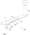
- Fig. 1 shows a winch handle, or more generally a crank arrangement 100, which in a releasable manner can be engaged with, and locked within, a winch socket 200 (cf. Fig.2 ) of a winch on a sailing boat wherein the winch socket 200 can be rotated when in engagement with a driving head 29 of the winch handle 10 rotating around an axis x.
- the winch handle 100 comprises an elongate crank arm 10 at, or close to, one end of which a handle part 40 is provided, substantially perpendicularly to the longitudinal extension of the crank arm 10.
- the crank arm 10 comprises a crank arm base section 10' and two hinged lever arms 11A, 11B extending in parallel on opposite outer sides of the crank arm base section 10' and receivable in hinged lever arm recesses 12A,12B provided on the opposite outer sides of the crank arm base section 10'.
- a protective cover element 13' is shown which is arranged to cover an upper recess 13 (cf. Fig 2 ).
- a hollow driving head 29 is provided which has an external engagement profile 30 allowing it to be axially introduced into a winch socket 200 receiving cavity 201 of a winch 210 (see Figs. 4A-4C ) with a receiving portion engagement profile mating with the engagement profile 30 of the driving head 29, in the shown embodiment an octagonal, star shaped, profile.
- a locking plate 25 is shown which is connected to an actuator connecting rod 26 of an actuator element 20 (cf. Fig. 2 ) housed in a rotatable manner within the driving head 29.
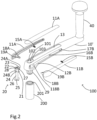
- Fig.2 is an exploded view of a first embodiment of the winch handle 100 according to the present invention.
- Fig. 2 for illustrative purposes very schematically illustrates a winch socket 200 with a receiving cavity 201 with which the winch handle 100 can be operatively engaged.
- Fig.2 shows the crank arm 10 comprising the crank arm base section 10' and the two elongate hinged lever arms 11A,11B.
- the crank arm base section 10' as referred to above comprises two elongate recesses 12A,12B, each for receiving one of said hinged lever arms 11A,11B.
- the hinged lever arms 11A,11B are pivotally mounted around each a rotation axis (not shown) disposed in openings 17A,17B in the crank arm base section 10' elongate recesses 12A,12B, the rotation axes extending in parallel, and being substantially perpendicular and vertically disposed with respect to the longitudinal extension of the crank arm 20 and located adjacent the end portions of the recesses 12A,12B distant from the driving head 29, and the end sections of the hinged lever arms 11A, 11B distant from the driving head 29.
- each lever arm 11A, 11B is allowed to rotate around its rotation axis between a first position in which it is substantially taken up in the recess 12A,12B, corresponding to an engagement/disengagement state in which the winch handle 100 can be engaged with/disengaged from a winch socket 200, and a second position wherein each lever arm 11A, 11B are pivoted outwards, away from the crank arm base section10', around their respective pivot axes, corresponding to a locking state, or an engaged state, in which the winch handle 100 can be locked in the winch socket 200, through the crank arm 10 being grabbed/released through a one hand gripping/releasing operation as will further described below.
- the hinged lever arms 11A, 11B are here spring biased or loaded by means of compression springs 15A,15B arranged between the crank arm base section 11' and a respective hinged lever arm 11A,11B to which they are connected.
- the compression springs 15A,15B are fastened by means of spring holding members (not shown) arranged in spring receiving openings 16A,16B in the crank lever arm recesses 12A,12B in the crank arm base section 10' and to the respective lever arms 11A, 11B at a distance from the rotation axes and urge the lever arms 11A, 11B to assume a second position, i.e. when the hinged lever arms are free, not gripped, or released from a grip, i.e.
- the lever arms 11A,11B, on their respective side sections facing the crank arm base section 10' each comprises a protruding actuating pin 18A, 18B, each actuating pin 18A,18B being perpendicular to the hinged lever arm 11A,11B on which it is disposed, and directed towards the crank arm base section 10', and located at different distances from the respective outer ends of the hinged lever arms (11A,11B).
- the crank arm base section 10' on each side comprises a transversal pin receiving opening 118A,118B (only 118B shown in Fig.2 ) which are arranged at a first and a second distance respectively from the outer end of the crank arm base section 10' distant from the handle part 40.
- the protruding actuating pins 18A, 18B are arranged at first and a second distance respectively from the end of the respective hinged lever arm 11A,11B, each protruding actuating pin 18A, 18B being provided with a gripping recess 19A,19B.
- the actuating pin 18A of first hinged lever arm 11A is here arranged at first distance from the end of the hinged lever arm 11A which is larger than the distance from the end of the other hinged lever arm 11B at which the second actuating pin 18B is located.
- the difference in distance from the respective end portions of the hinged lever arms 11A,11B to the respective actuating pins 18A, 18B is such as to allow reception of an actuating member 21 of a rotatable actuator element 20, as will be more thoroughly described below, between the actuating pins 18A, 18B in such a way that gripping recess 19A on hinged lever arm 11A mates with a first actuation shoulder 24A of the actuating member 21 and gripping recess 19B on hinged lever arm 11B mates with a second actuation shoulder 24B of the actuating member 21, hence allowing the interaction between the hinged lever arms 11A,11B and the rotatable actuator element 20.
- hinged lever arms 11A, 11B are both operatively connected to the rotatable actuator element 20, either one of, or both hinged lever arms 11A, 11B can be pressed/released (moved between a loaded state in which a load is applied to the compression spring, the compression spring is compressed, and a released state in which no force is applied to the compression spring) to move the actuator element 20, and hence to achieve the engagement/disengagement state and the locking state respectively.
- the protruding actuating pins may be provided with protrusions for engagement with recesses provided in the actuation shoulders instead.
- the crank arm base section 10' on an upper side comprises a keyhole shaped recess 101, the narrow end 103 of the keyhole, in the following denoted cutout, being directed towards the handle part 40, the circular part 102 of the keyhole shaped recess 101 facing the outer end of the crank arm base section 10' and being coaxial with a hollow driving head 29 here having an octagonal external shape, engagement profile 30.
- the keyhole shaped recess 101 has a depth substantially corresponding to the height of an upper plate 22 of actuator element 20.
- the upper plate 22 of the actuator element 20 comprises a circularly shaped plate of substantially the same dimensions as the key hole circular recess 102, but slightly smaller allowing it to be received therein, and an actuation protrusion 23 with dimensions smaller than the narrow part 103 of the keyhole (the cutout) to allow rotation of the upper plate 22 between a first position in which the actuation protrusion 23 is blocked by a side wall 103' of narrow portion or cutout 103 and in which the winch handle 100 is in a position allowing engagement/disengagement of the winch handle 100, and a second position in which the actuation protrusion 23 is blocked by an opposed wall 103" of the cutout 103 of the keyhole 101 corresponding to a locked position (a neutral position) in which the winch handle 100 is locked when received in a winch socket receiving cavity 201, and the hinged lever arms 11A,11B released (and rotated outwardly) as will further described below. In the second position the winch handle 100 cannot be engaged with/disengaged from
- the actuator element 20 further comprises a locking plate 25 of, here, a substantially square shaped transverse cross-section, connecting to a lower end of an actuator connecting rod 26 at the opposed end of which actuating member 21 of the actuator element 20 is provided.
- the actuating member 21 comprising the upper plate 22 with the actuation protrusion 23 further comprises a first actuation shoulder 24A and a second actuation shoulder 24B which are provided on opposed sides of an actuating member 21 cylindrical receiving portion 24 and extend axially downwards from the upper plate 22.
- the first actuation shoulder 24A and the second actuation shoulder 24B protrude on opposite sides of the cylindrical receiving portion 24 which is adapted to receive the actuator connecting rod 26 and extend a certain distance in the direction towards the locking plate 25.
- the first and second actuation shoulders 24A, 24B are so arranged that the first actuation shoulder 24A will be actuated upon through engagement with the first actuating pin 18A recess 19A and the second actuation shoulder 24B will be actuated upon through engagement with the second actuating pin 18B recess 19B when the hinged lever arms 11A,11B are gripped, moving the actuating pins 18A,18B through pin openings 118A, 118B in the crank arm base section 10' and hence rotate the actuating member 21, as well as when the hinged lever arms 11A,11B are released, the actuating member 21 will be actuated upon to rotate in the opposite direction. When the actuating member 21 is rotated, also the locking plate 25 will be rotated.
- the rotational movement of the actuator element 20 received in driving head 29 is thus limited through the shoulders 24A,24B being blocked when getting in contact with inner walls 103',103" of the keyhole narrow portion 103, or cutout, in the crank arm base portion 10'.
- the rotational movement is limited to 22.5° (1/16 of a full turn).
- the locking plate 25 is connected, e.g. fixedly, to the actuating member 21 via the actuating element rod 26 such that also the locking plate 25 will be rotated when the actuating member 21 is rotated by means of the actuating shoulders 24A,24B being actuated upon via the protruding pins 18A,18B when the crank arm 10 is gripped and the hinged lever arms 18A,18B hence pushed against the action of the springs 15A,15B.
- the locking plate 25 When the locking plate 25 is rotated 1/16 of a full turn, the locking plate 25 will be aligned with the external engagement profile 30 of the driving head 29, integral with the crank arm base section 10', or fixedly secured thereto, which in turn allows alignment with a mating star shaped geometry, octagonal shape, of the winch socket 200 receiving portion 201 allowing introduction of the driving head 29 into the winch socket receiving portion 201 and removal of the driving head 29 from the winch socket receiving portion 201 through a downwards directed axial movement and an upwards directed axial movement respectively.
- the locking plate 25 is misaligned with external engagement profile 30 of the driving head 29 and hence also with the winch socket 200 receiving cavity 201 geometry (see Fig.4B ) by the hinged lever arms 11A, 11B being urged outwardly by the springs 15A,15B, and via the actuating pins 18A,1( actuation upon the actuating element 21 as described above.
- the actuating connecting rod 26 in the shown embodiment is secured to the upper side of the actuating member upper plate 22 through which the actuator connecting rod 26 is received and protrudes by means of a securing portion 27 connected to, or integral with, the end of the actuator connecting rod 26.
- the securing portion 27 which comprises a through locking hole orthogonal to the rotation axis of the rod 27 for reception of a locking pin 28. It should be clear that the actuator connecting rod 26 can be secured to the actuating member 21 through any appropriate alternative means, or in any appropriate manner, this just illustrating one exemplary embodiment.
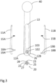
- Fig.3 is an exploded view from above of the winch handle 10 of Fig.2 shown for illustrative purposes, and to more clearly show the hinged lever arms 11A, 11B and the positioning of the actuating pins 18A,18B with recesses 19A,19B as discussed with reference to Fig.2 .
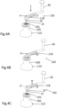
- Fig.4A schematically illustrates how the winch handle 100 is operated for engagement with a winch socket 200.
- One or both hinged lever arms 11A, 11B are pressed (arrows P,P), e.g. by the winch handle 100 simply being manually grabbed anywhere along the crank arm.
- locking plate 25 will be rotated, allowing the driving head 29 to be received in the winch socket receiving cavity 201, by the locking plate 25 being aligned with the external engagement profile 30 of the driving head 29 and hence also with the winch socket 200 receiving cavity 201 star shaped octagonal engagement profile.
- Fig.4B illustrates how the winch handle 100 is locked to the winch socket 200.
- Fig. 4C schematically illustrates how the handle 100 is operated for disengagement from a winch socket 200.
- the winch handle 20 is simply grabbed, one or both the hinged lever arms 11A, 11A being pushed inwards towards the crank arm base section (dashed arrows D,D) and the winch handle can be lifted up, which is enabled through the actuation on the locking plate 25 by means of actuating pins 18A,18B as described above, such that it will be aligned with the external engagement profile 30 of the driving head 29, the geometry of which hence being aligned with the geometry of the receiving cavity 201 of the winch socket receiving portion or cavity 201, thus allowing disengagement.
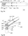
- Fig.5A is a cross-sectional view taken through the winch handle along the section A-A in Fig.1 in a state allowing engagement with, or disengagement from, a winch socket.
- the hinged lever arms 11A, 11B have been gripped, urged against the action of the springs 15A, 15B, and pivoted around their rotation axes in pivot arm recesses 17A,17B such that they are taken up in the crank arm recesses 12,12B in the crank arm base section 10'.
- Actuating pins 18A,18B protruding perpendicularly to the longitudinal extension of the respective hinged lever arms 11A, 11B and arranged at different distances from outer ends of the hinged lever arms 11A, 11B have actuated upon actuating member 21 by means of the pin gripping recess 19A engaging with first actuation shoulder 24A of the actuating member 21, pin gripping recess 19B engaging with second actuation shoulder 24B of the actuating member 21, rotating it, in this embodiment, clock-wise, until the actuating member 21 upper plate 22 is blocked from further rotation by protrusion 22 reaching wall 103' of the cutout 103 in the crank arm base section 10'; not shown in Fig.5A ; cf. see Fig.5E .
- Fig.5B is a view in perspective from above of the winch handle 100 in the same position as in Fig.5A , i.e. in a position for engagement with winch socket 200, or just after disengagement from the winch socket 200 (the part of the winch handle with the handle part has been excluded since it has been shown above and no details are affected and need to be shown in order to explain the functionality).
- Fig.5C is a schematic view from below of the end portion of the winch handle 100 showing the position of the locking plate 25 with respect to the octagonal engagement profile 30 of the driving head 29, wherein the square shaped locking plate 25 is so arranged that every second corner of the octagon coincides with a corner of the locking plate 25.
- Fig 5D is a cross-sectional view taken vertically through part of the winch handle 100 along the section B1-B1 in Fig.5C and through a winch socket 200 in which the winch handle is in a state allowing engagement as in Figs. 5A-5C .
- Fig.5D can particularly be seen how the actuating element protrusion 23 is located in the cutout 103 and the first and second actuating shoulders 24A,24B being actuated upon by the actuating pins 18A,18B. It also shows the locking element 25 interconnected via the actuator connecting rod 26 with the actuating member 21 of the actuator element 20, and protruding out of the driving head 29 having an octagonal external engagement profile 30.
- Fig. 5E is an enlarged view from above of the front portion of the winch handle 100 illustrating the actuating member 21 with the locking pin 28 introduced through the locking opening in securing portion 27 for securing the actuator connecting rod 26 with the locking plate 26 to the actuating member 21 and the crank arm base section 10', and with the actuating member protrusion 23 in a position wherein it is blocked by the wall 103' of the cutout 103 from further rotation in an engagement position as in Figs 5A-5D .
- elements already discussed with reference to the preceding figures will not be further discussed here.
- Fig.6A is a cross-sectional view taken through the winch handle along the section A-A in Fig.1 similar to Fig. 5A but in a state in which the winch handle 100, with the driving head 29, cf. e.g. Fig.2 , Fig.5D ) introduced into a receiving cavity 201 of a winch socket 200 (cf. Fig. 6B ), is locked therein.
- the hinged lever arms 11A, 11B After introduction of the driving head 29 into the winch socket 200, the hinged lever arms 11A, 11B have been released, urged by means of the springs 15A,15B, and pivoted around their rotation axes at pivot arm recesses 17A,17B such that they are rotated to protrude slightly from the recesses 12,12B in direction towards the front end of the crank arm base section 10'.
- Actuating pins 18A,18B have actuated upon actuating element 21 by means of the pin gripping recess 19A engaging with first actuation shoulder 24A of the actuating member 21, pin gripping recess 19B engaging with second actuation shoulder 24B of the actuating member 21, rotating it, in this embodiment counter clock-wise, until it is blocked from further rotation by the actuating member 21 upper plate 22 protrusion 22 reaching wall 103" of the cutout 103 in the crank arm base section 10'; not shown in Fig.6A ; cf. see Fig.6E .
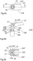
- Fig.6B is a view in perspective from above of the winch handle 100 in the same position as in Fig.6A , i.e. in a locking state within a winch socket 200 (as in Fig.5B the part of the winch handle comprising the handle part has been excluded since it has been shown above and no details are affected and need to be shown in order to explain the functionality).
- Fig.6C is a schematic view from below of the end portion of the winch handle 100 in a locking state showing the position of the locking plate 25 being misaligned with respect to the octagonal engagement profile 30 of the driving head 29, the square shaped locking plate 25 being so arranged that instead of an external profile in the shape of an octagon, the driving head 29 with the locking plate 25 will provide an external profile having 12 vertices, a dodecagon.
- Fig 6D is a cross-sectional view taken vertically through part of the winch handle 100 along the section B'-B' in Fig.6C and through a winch socket 200 in which the winch handle is in a locking state as in Figs. 6A-6C .
- Fig.6D can particularly be seen how the actuating element protrusion 23 is located in the cutout 103 and the first and second actuating shoulders 24A,24B being actuated upon by the actuating pins 18A, 18B.
- Fig. 6E is an enlarged view from above of the front portion of the winch handle illustrating the actuating member 21 with the locking pin 28 introduced through the locking opening in securing portion 27 for securing the actuating element rod 26 with the locking plate 26 to the actuating member 21 and the crank arm base section 20', and with the actuating member protrusion 23 in a position wherein it is blocked by the wall 103" of the cutout 103 from further rotation in an engagement position as in Figs 6A-6D .
- elements already discussed with reference to the preceding figures will not be further discussed here.
- the actuating member 21, to which the locking plate 25 is fixedly connected via the actuator connecting rod 26, which is taken up within the actuating member 21 cylindrical receiving portion 24, is here axially secured to the crank arm base portion 10' by means of the locking pin 28 introduced through an opening in the securing portion 27 of the actuator connecting rod 26 protruding through a recess in the upper plate 22 of the actuating member 21.
- the present invention is not limited to a winch handle with an octagonal shape for a winch socket having an internal octagonal engagement profile; essential being that in an engagement position the locking plate and the external profile of the handle driving head are aligned, and correspond to an engagement profile of a receiving portion of a winch socket, whereas in a locking position they are misaligned, preventing voluntary or accidental removal of the winch handle from the winch socket, and that a grip anywhere along the crank arm can be used to allow alignment of the locking plate with the external profile of the driving head, allowing axial insertion into/removal from a winch socket, and the inventive concept is also not limited to a particular winch socket or a winch socket such as shown and described with reference to the in Fig.1 , Figs.4A-4C illustrated embodiment; on the contrary it may be of different kinds and be varied in a number of different manners.
- a winch handle may, instead of one or more hinged lever arms, comprise one or more operating elements in form of spring biased slidingly and/or translationally movable elements or lever arms performing a sliding or translational movement in a horizontal plane, in parallel with the crank arm base section, or transversal to the longitudinal extension of the crank arm base section can be used, allowing a one hand grip for exerting or applying a force on a spring element to bring it into an engagement/disengagement state and release of the hand grip to bring it into locked state in which engagement/disengagement (release) is prevented.
- the shape of the locking element and of the external engagement profile of the driving head may be different, as long as, through rotation of the locking plate in one direction, it is aligned with the engagement profile, whereas through rotation in an opposite direction, it is brought into misalignment with the engagement profile; other shapes of locking plate, and other polygonal engagement profiles hence being possible.
- cranking arrangement particularly a winch handle
- a driving arrangement particularly, but not exclusively, a manually operable winch for a sailing boat
- gripping anywhere along the elongate crank arm using only one hand, e.g. a palm grip, and which when engaged, cannot be accidentally removed, but is securely locked thereto.
- cranking arrangement which is robust and wear resistant.
- a solution is provided which combines a rotational locking mechanism with a one hand grip mechanism for engagement/disengagement.
Landscapes
- Engineering & Computer Science (AREA)
- Physics & Mathematics (AREA)
- General Physics & Mathematics (AREA)
- Automation & Control Theory (AREA)
- Mechanical Engineering (AREA)
- Lock And Its Accessories (AREA)
- Lubrication Of Internal Combustion Engines (AREA)
- Cylinder Crankcases Of Internal Combustion Engines (AREA)
Claims (17)
- Kurbelanordnung (100) zum Betätigen einer Antriebsanordnung, wobei die Kurbelanordnung (100) aufweist: einen verlängerten Kurbelarm (10) mit einem hohlen Antriebskopf (29), der an einem Ende davon angeordnet ist, und einer Griffpartie (40) bei einer Entfernung von dem Antriebskopf (29), wobei der Antriebskopf (29) und die Griffpartie (40) im Wesentlichen senkrecht zu dem Kurbelarm (10) in im Wesentlichen entgegengesetzten Richtungen vorstehen, wobei der Antriebskopf (29) ein äußeres Eingriffsprofil (30) aufweist; eine Sperrplatte (25), die an einem äußeren Ende eines Aktuatorbauteils (20) angeordnet ist, das drehbar innerhalb des hohlen Antriebskopfes (29) aufgenommen ist; eine Hebelanordnung (11A, 11B) zum Drehen der Sperrplatte (25) von einer zweiten Position, in der die Sperrplatte (25) mit dem Eingriffsprofil (30) des Antriebskopfes (30) fehlausgerichtet ist, zu einer ersten Position, in der die Sperrplatte (25) mit dem Eingriffsprofil (30) des Antriebskopfes (29) ausgerichtet ist,
dadurch gekennzeichnet,
dass die Hebelanordnung (11A, 11B) mindestens einen federgespannten Hebelarm (11A, 11B) aufweist, der sich parallel zu einer äußeren Längswand des Kurbelalarms (10) erstreckt und bewegbar, zum Beispiel translatorisch oder rotatorisch, bezüglich eines Kurbelarmbasisabschnittes (10') montiert ist, wobei der mindestens eine Hebelarm (11A, 11B) Eingriffseinrichtungen (18A, 18B) aufweist, die dazu angepasst sind, wenn der Kurbelarm (10) gegriffen wird, sodass mindestens einer des mindestens einen Hebelarms (11A, 11B) bewegt wird, auf ein Einwirkelement (21) des Aktuatorbauteils (20) einzuwirken, das mit der Sperrplatte (25) verbunden ist, sodass die Sperrplatte (25) eine Drehbewegung in einer Richtung durchführen wird, zum Annehmen der ersten Position, bei der sie mit dem Eingriffsprofil (30) des Antriebskopfes (29) ausgerichtet ist, wohingegen, wenn der mindestens eine Hebelarm (11A, 11B) freigegeben wird, auf die Sperrplatte (25) eingewirkt werden wird, zum Durchführen einer Drehbewegung in einer entgegengesetzten Richtung, zum Annehmen der zweiten Position, in der die Sperrplatte (25) mit dem Eingriffsprofil (30) des Antriebskopfes (29) fehlausgerichtet ist, dass Einrichtungen zum Beschränken der Drehbewegung des Einwirkelements (21) vorgesehen sind, und dadurch, dass die Sperrplatte (25) von der zweiten, fehlausgerichteten Position zu der ersten, ausgerichteten Position überführt werden kann, einen Eingriff mit einer Antriebsanordnung mittels eines Greifens des Kurbelarms (10) mit einer Hand während eines Bewegens des Hebelarms (10A, 10B) gegen die Federwirkung ermöglichend, und dadurch, dass die Sperrplatte (25) von der ersten, ausgerichteten Position zu der zweiten, fehlausgerichteten Position überführt werden kann, an eine Antriebsanordnung sperrend, mittels eines Freigebens des Griffs auf den Kurbelarm (10). - Kurbelanordnung (100) gemäß Anspruch 1,
dadurch gekennzeichnet,
dass die Kurbelanordnung (100) einen Windengriff zum Betätigen einer Winde (210) aufweist. - Kurbelanordnung (100) gemäß Anspruch 2,
dadurch gekennzeichnet,
dass, wenn die Sperrplatte (25) in der ersten Position und mit dem Eingriffsprofil (30) des Antriebskopfes (29) ausgerichtet ist, ein In-Eingriff-Kommen mit/ Außer-Eingriff-Kommen von einem Windensockel (200) ermöglicht ist, und dadurch, dass, wenn der/die Klapphebelarm/e (11A, 11B) freigegeben ist/sind und die Sperrplatte (25) zum Annehmen der zweiten Position gedreht ist und mit dem Eingriffsprofil (30) des Antriebskopfes (29) fehlausgerichtet ist, der Antriebskopf (29), der in einer Aufnahmekavität (201) einer Antriebsanordnung (200) aufgenommen ist, an die Antriebsanordnung (200) gesperrt ist. - Kurbelanordnung (100) gemäß einem der Ansprüche 1 bis 3,
dadurch gekennzeichnet,
dass die Hebelanordnung (11A, 11B) zwei Klapphebelarme (11A, 11B) aufweist, die sich parallel an entgegengesetzten äußeren Seitenwänden des Kurbelarms (10) erstrecken, wobei jeder Klapphebelarm (11A, 11B) schwenkbar um eine jeweilige Drehachse montiert ist, zum Beispiel in einer jeweiligen Öffnung oder Vertiefung (17A, 17B) in dem Kurbelbasisabschnitt (10') bei einer Entfernung von dem Endabschnitt angeordnet ist, bei dem die Griffpartie (40) angeordnet ist, und mittels einer jeweiligen Druckfeder (15A, 15B) auswärts gedrängt wird, wobei jeder Klapphebelarm (11A, 11B) an entgegengesetzten Endabschnitten betätigbar mit dem Aktuatorbauteil (20) verbunden ist, wobei die Klapphebelarme (11A, 11B) somit durch Drehung bewegbar sind. - Kurbelanordnung (100) gemäß Anspruch 4,
dadurch gekennzeichnet,
dass jede Eingriffseinrichtung des Klapphebelarms (11A, 11B) einen vorstehenden Stift (18A, 18B) aufweist, wobei jeder vorstehende Stift (18A, 18B) bei einer jeweiligen Entfernung von dem äußeren Ende des jeweiligen Klapphebelarms (11A, 11B) liegt, wobei die Entfernung von dem äußeren Ende von einem der Klapphebelarme (11A), bei dem einer der vorstehenden Stifte (18A) liegt, die Entfernung von dem äußeren Ende des anderen Klapphebelarms (11B) übersteigt, bei dem der andere vorstehende Stift (18B) liegt, sodass einer der vorstehenden Stifte (18A) mittels einer Öffnung (118A) an einer Seite des Kurbelarmbasisabschnitts (10') mit einer Einwirkschulter (24A), die an einer äußeren Seite des Einwirkelements (21) vorgesehen ist, in Eingriff kommen wird und der andere vorstehende Stift (18B) mittels einer Öffnung (118B) an der entgegengesetzten Seite des Kurbelarmbasisabschnitts (10') mit einer Einwirkschulter (24B), die an einer entgegengesetzten äußeren Seite des Einwirkelements (21) vorgesehen ist, in Eingriff kommen wird, es somit dem Einwirkbauteil (21) ermöglichend, gedreht zu werden, wenn der Kurbelarm (10) gegriffen wird, sodass mindestens einer der Klapphebelarme (11A, 11B) in Richtung des Kurbelbasisabschnitts (10') gedrängt wird. - Kurbelanordnung (100) gemäß Anspruch 5,
dadurch gekennzeichnet,
dass jeder vorstehende Stift (18A, 18B) eine Greifvertiefung (19A, 19B) aufweist, wobei die Greifvertiefungen (19A, 19B) dazu angepasst sind, mit der jeweiligen Einwirkschulter (24A, 24B) in Eingriff zu kommen. - Kurbelanordnung (100) gemäß Anspruch 5,
dadurch gekennzeichnet,
dass jeder vorstehende Stift (18A, 18B) einen Vorsprung aufweist, wobei die Vorsprünge dazu angepasst sind, mit einer Vertiefung in der jeweiligen Einwirkschulter (24A, 24B) in Eingriff zu kommen. - Kurbelanordnung (100) gemäß Anspruch 6 oder 7,
dadurch gekennzeichnet,
dass das Einwirkelement (21) einen hohlen oberen zylindrischen Abschnitt (24), der dazu angepasst ist, ein oberes Ende einer Aktuatorverbindungsstange (26) aufzunehmen, eine obere Platte (22) aufweist, die eine kreisförmige Platte mit einem Einwirkvorsprung (23) aufweist, wobei die Einwirkschultern (24A, 24B) an entgegengesetzten Seiten des zylindrischen Aufnahmeabschnitts (24) des Einwirkelements (21) vorgesehen sind und sich von der oberen Platte (22) in der Richtung zu der Sperrplatte (25) axial abwärts erstrecken. - Kurbelanordnung (100) gemäß Anspruch 8,
dadurch gekennzeichnet,
dass der Kurbelarmbasisabschnitt (10') an einer oberen Seite eine schlüssellochförmige Vertiefung (101) aufweist, die einen kreisförmigen Abschnitt (102), der mit dem hohlen Antriebskopf (29) koaxial ist, und einen Ausschnitt (103) aufweist, der in Richtung zu der Griffpartie (40) gerichtet ist, wobei der Ausschnitt (103) die Blockiereinrichtung ausbildet, wobei die schlüssellochförmige Vertiefung (101) so dimensioniert ist und liegt, dass sie eine Aufnahme der oberen Platte (22) des Einwirkbauteils (21) ermöglicht, wobei die kreisförmige obere Platte (22) des Aktuatorbauteils (20) im Wesentlichen dieselben Abmessungen hat wie die kreisförmige Vertiefung (102), aber etwas kleiner, was es ihr ermöglicht, darin aufgenommen zu werden, wobei der Einwirkvorsprung (23) der oberen Platte (22) Querabmessungen hat, die kleiner sind als der Ausschnitt (103), was eine Drehung der oberen Platte (22) zwischen einer ersten Position, in der der Einwirkvorsprung (23) durch eine Seitenwand (103') des Ausschnitts (103) blockiert ist, wenn der Kurbelarm derart gegriffen wird, dass der mindestens eine Klapphebelarm (11A, 11B) in Richtung des Kurbelarmbasisabschnitts (10') gedrückt wird, was ein In-Eingriff-Kommen/Außer-Eingriff-Kommen der Kurbelanordnung (100) ermöglicht, und einer zweiten Position ermöglicht, in der der Einwirkvorsprung (23) durch eine entgegengesetzte Wand (103") des Ausschnitts (103) blockiert ist, die zu einer gesperrten Position (einer neutralen Position) korrespondiert, in der der mindestens eine Klapphebelarm (11A, 11B) freigegeben ist und in der der Windengriff (100) nicht mit einem Windensockel (200) in Eingriff gebracht werden kann/von diesem außer Eingriff gebracht werden kann. - Kurbelanordnung (100) gemäß einem der vorangehenden Ansprüche,
dadurch gekennzeichnet,
dass der Antriebskopf (29) eine achteckige Querschnittsaußenform hat, die die Eingriffsfläche (30) ausbildet, und dass die Sperrplatte (25) quadratförmig ist. - Kurbelanordnung (100) gemäß Anspruch 10,
dadurch gekennzeichnet,
dass zum Drehen des Einwirkbauteils (21) von der ersten Position zu der zweiten Position und umgekehrt dieses um einen Winkel von 22,5° gedreht wird, der zu einem Sechzehntel einer vollen Umdrehung korrespondiert, wobei eine Drehung von der ersten zu der zweiten, sperrenden Position automatisch durch eine Freigabe der Klapphebelarme (11A, 11B) erreicht wird. - Kurbelanordnung (100) zumindest gemäß Anspruch 8,
dadurch gekennzeichnet,
dass das Aktuatorbauteil (20) ferner einen Sicherungsabschnitt (27) aufweist, der mit einem oberen Ende der Aktuatorverbindungsstange (26)verbunden oder einstückig ist, das zu dem Ende entgegengesetzt ist, bei dem die Sperrplatte (25) vorgesehen ist, wobei das obere Ende durch die obere Platte (22) vorsteht und der Sicherungsabschnitt (27) an einer oberen Seite der oberen Platte (22) angeordnet ist, wobei der Sicherungsabschnitt (27) eine Durchgangsöffnung zur Aufnahme eines Sperrstifts (28) aufweist, der das Aktuatorbauteil (20) axial an dem Kurbelarmbasisabschnitt (10') sperrt. - Kurbelanordnung (100) zumindest gemäß Anspruch 4,
dadurch gekennzeichnet,
dass der Kurbelarmbasisabschnitt (10') zwei verlängerte Vertiefungen (12A, 12B) aufweist, die an entgegengesetzten äußeren Seiten vorgesehen sind und zur Aufnahme der Klapphebelarme (11A, 11B) angepasst sind, sodass, wenn diese gegriffen sind und einwärts gegen die Wirkung der Druckfedern (15A, 15B) gedrängt sind und um ihre Drehachsen geschwenkt sind, diese im Wesentlichen in den verlängerten Vertiefungen (12A, 12B) aufgenommen sind, wohingegen in einer freigegebenen Position jeweilige Vorderabschnitte der Klapphebelarme (11A, 11B) etwas von den verlängerten Vertiefungen (12A, 12B) vorstehen. - Kurbelanordnung (100) gemäß Anspruch 9,
dadurch gekennzeichnet,
dass der Kurbelarmbasisabschnitt (10') eine obere Vertiefung (13), in deren Vorderende die schlüssellochförmige Vertiefung (101) liegt, und ein Schutzabdeckungsbauteil (13') aufweist, das dazu angepasst ist, die obere Vertiefung (13) abzudecken, wobei das Schutzabdeckungsbauteil (13') fest oder lösbar mit dem Kurbelarmbasisabschnitt (10') verbunden ist. - Kurbelanordnung (100) gemäß einem der vorangehenden Ansprüche,
dadurch gekennzeichnet,
dass die Sperrplatte (25) drehbar mit dem Einwirkelement (21) gekuppelt ist. - Baugruppe, die eine Winde (210) für ein Segelboot und einen Windengriff (100) zur manuellen Betätigung der Winde (210) aufweist,
dadurch gekennzeichnet,
dass der Windengriff eine Kurbelanordnung (100) nach einem der Ansprüche 1 bis 15 aufweist, dass die Winde (210) einen Windensockel (201) mit einem inneren Eingriffsprofil aufweist, das sich mit dem äußeren Eingriffsprofil (30) des Antriebskopfes (29) der Kurbelanordnung fügt, wobei die Eingriffsprofile zum Beispiel eine achteckige Querschnittsform haben. - Verwendung einer Kurbelanordnung gemäß einem der Ansprüche 1 bis 15 zum manuellen Betätigen einer Segelbootwinde.
Applications Claiming Priority (2)
| Application Number | Priority Date | Filing Date | Title |
|---|---|---|---|
| SE2150687A SE545360C2 (en) | 2021-05-28 | 2021-05-28 | A crank arrangement |
| PCT/SE2022/050328 WO2022250587A1 (en) | 2021-05-28 | 2022-04-01 | A crank arrangement |
Publications (2)
| Publication Number | Publication Date |
|---|---|
| EP4347475A1 EP4347475A1 (de) | 2024-04-10 |
| EP4347475B1 true EP4347475B1 (de) | 2025-05-21 |
Family
ID=81326379
Family Applications (1)
| Application Number | Title | Priority Date | Filing Date |
|---|---|---|---|
| EP22715796.3A Active EP4347475B1 (de) | 2021-05-28 | 2022-04-01 | Kurbelanordnung |
Country Status (5)
| Country | Link |
|---|---|
| US (1) | US12617658B2 (de) |
| EP (1) | EP4347475B1 (de) |
| DK (1) | DK4347475T3 (de) |
| SE (1) | SE545360C2 (de) |
| WO (1) | WO2022250587A1 (de) |
Families Citing this family (2)
| Publication number | Priority date | Publication date | Assignee | Title |
|---|---|---|---|---|
| SE545055C2 (en) | 2021-01-13 | 2023-03-14 | Selden Mast Ab | A winch arrangement for a sailing boat |
| SE545360C2 (en) | 2021-05-28 | 2023-07-18 | Selden Mast Ab | A crank arrangement |
Family Cites Families (25)
| Publication number | Priority date | Publication date | Assignee | Title |
|---|---|---|---|---|
| GB1371994A (en) | 1972-04-18 | 1974-10-30 | Francis B F | Sail rigging |
| JPS57125631A (en) * | 1981-01-27 | 1982-08-05 | Daiwa Seiko Co | Handle folding apparatus of fishing reel |
| US4582298A (en) * | 1984-03-05 | 1986-04-15 | Barient, Inc. | Variable radius crank winch |
| US4924795A (en) | 1988-11-18 | 1990-05-15 | International Marine Industries | Winch for roller reefing |
| US5255573A (en) * | 1992-01-22 | 1993-10-26 | Harken, Inc. | Winch handle |
| DE4232329A1 (de) * | 1992-09-26 | 1994-03-31 | Ewald Ettrich | Ratschenkurbel mit Mittelarretierung |
| US5370366A (en) | 1993-02-23 | 1994-12-06 | Harken, Inc. | Backwind sailboat winch |
| US5582080A (en) * | 1994-09-26 | 1996-12-10 | Barmore; Thomas C. | Ratchet wrench |
| US5833217A (en) * | 1996-11-25 | 1998-11-10 | Goldsby; Alan T. | Detachable two-handed crank handle for nautical winch |
| DE20000724U1 (de) | 2000-01-18 | 2001-05-31 | Meyerdierks Helmut | Motorwinsch |
| US6491285B1 (en) * | 2000-10-10 | 2002-12-10 | Paul K. Tomita | Winch handle retention system |
| US6921060B2 (en) * | 2003-06-12 | 2005-07-26 | Ronald Thomas Weed, Jr. | Winch handle |
| DE10348642B4 (de) * | 2003-10-15 | 2010-05-20 | Aat Alber Antriebstechnik Gmbh | Handgriff zur Betätigung eines motorischen Hilfsantriebs |
| US7114705B2 (en) | 2004-03-30 | 2006-10-03 | Steiner Donald J | Grab-activated self-locking winch handle |
| GB0409253D0 (en) | 2004-04-26 | 2004-05-26 | Lewmar Ltd | Winch and winch drum |
| WO2008119108A1 (en) * | 2007-03-30 | 2008-10-09 | Goodcart Pty Ltd | Guide for a winch crank |
| NL1036523C2 (nl) | 2009-02-06 | 2010-08-09 | Holmatro Ind Equip | Lier met groeven in het manteloppervlak van de trommel. |
| NL2003675C2 (nl) * | 2009-10-20 | 2011-04-21 | Holmatro Ind Equip | Lierhendel. |
| CN204921926U (zh) | 2015-08-13 | 2015-12-30 | 南京高精船用设备有限公司 | 封闭行星齿轮箱 |
| CN108046147A (zh) | 2017-12-28 | 2018-05-18 | 南京高速齿轮制造有限公司 | 与卷筒一体化的起重机用减速箱 |
| CN210686874U (zh) | 2019-10-09 | 2020-06-05 | 浙江赛亚智能传动科技有限公司 | 一种新型多级行星减速器 |
| SE546972C2 (en) | 2019-11-13 | 2025-03-18 | Selden Mast Ab | An arrangement for a sailing boat furling system and a furling system with such an arrangement |
| SE545055C2 (en) | 2021-01-13 | 2023-03-14 | Selden Mast Ab | A winch arrangement for a sailing boat |
| SE545360C2 (en) | 2021-05-28 | 2023-07-18 | Selden Mast Ab | A crank arrangement |
| SE546135C2 (en) | 2022-10-07 | 2024-06-04 | Selden Mast Ab | A winch drum with a number of protrusions or ribs and a winch with such a winch drum |
-
2021
- 2021-05-28 SE SE2150687A patent/SE545360C2/en unknown
-
2022
- 2022-04-01 DK DK22715796.3T patent/DK4347475T3/da active
- 2022-04-01 US US18/285,479 patent/US12617658B2/en active Active
- 2022-04-01 EP EP22715796.3A patent/EP4347475B1/de active Active
- 2022-04-01 WO PCT/SE2022/050328 patent/WO2022250587A1/en not_active Ceased
Also Published As
| Publication number | Publication date |
|---|---|
| US12617658B2 (en) | 2026-05-05 |
| WO2022250587A1 (en) | 2022-12-01 |
| EP4347475A1 (de) | 2024-04-10 |
| DK4347475T3 (da) | 2025-06-30 |
| SE2150687A1 (en) | 2022-11-29 |
| SE545360C2 (en) | 2023-07-18 |
| US20240182277A1 (en) | 2024-06-06 |
Similar Documents
| Publication | Publication Date | Title |
|---|---|---|
| US12617658B2 (en) | Crank arrangement | |
| EP2620258B1 (de) | Verriegelungszangen mit Griffsperrmechanismus | |
| JP4338633B2 (ja) | 船舶積載用コンテナの自動ロッキング装置 | |
| CN215402777U (zh) | 可安全打开的滑轮装置 | |
| US8167273B2 (en) | Spring-latched connection for torque transmitting shaft | |
| EP2305431B1 (de) | Selbstverriegelnde Kurbel für eine Winde | |
| CN111512405B (zh) | 电气开关的旋转手柄结构件 | |
| US5833217A (en) | Detachable two-handed crank handle for nautical winch | |
| CN114391069A (zh) | 带致动按钮和释放按钮的水下钩 | |
| US4094047A (en) | Snap shackle | |
| CN106837013B (zh) | 一种行李箱提手锁及行李箱 | |
| US8851003B2 (en) | Sailboat halyard lock | |
| EP1004541A1 (de) | Verfahren zum Verriegelen von einem Wirbel eines Rollenblockes | |
| EP2232351B1 (de) | Lösemechanismus für einen schotwindengriff | |
| WO2008119108A1 (en) | Guide for a winch crank | |
| KR100485511B1 (ko) | 선박 적재용 컨테이너의 자동 결속장치 | |
| EP2490978A1 (de) | Winschkurbel | |
| GB2086547A (en) | Halyard stopper | |
| EP3293140B1 (de) | Haken mit verriegelung- und auslösemechanismus | |
| EP4140937B1 (de) | Hebevorrichtung für schachtabdeckungen oder ähnliches | |
| HK1077549B (en) | Apparatus for automatically locking ship containers | |
| HK1110372B (en) | A device for mechanical guiding, a lock module and a lock device comprising such a device | |
| HK1110372A1 (en) | A device for mechanical guiding, a lock module and a lock device comprising such a device |
Legal Events
| Date | Code | Title | Description |
|---|---|---|---|
| STAA | Information on the status of an ep patent application or granted ep patent |
Free format text: STATUS: UNKNOWN |
|
| STAA | Information on the status of an ep patent application or granted ep patent |
Free format text: STATUS: THE INTERNATIONAL PUBLICATION HAS BEEN MADE |
|
| PUAI | Public reference made under article 153(3) epc to a published international application that has entered the european phase |
Free format text: ORIGINAL CODE: 0009012 |
|
| STAA | Information on the status of an ep patent application or granted ep patent |
Free format text: STATUS: REQUEST FOR EXAMINATION WAS MADE |
|
| 17P | Request for examination filed |
Effective date: 20231101 |
|
| AK | Designated contracting states |
Kind code of ref document: A1 Designated state(s): AL AT BE BG CH CY CZ DE DK EE ES FI FR GB GR HR HU IE IS IT LI LT LU LV MC MK MT NL NO PL PT RO RS SE SI SK SM TR |
|
| DAV | Request for validation of the european patent (deleted) | ||
| DAX | Request for extension of the european patent (deleted) | ||
| GRAP | Despatch of communication of intention to grant a patent |
Free format text: ORIGINAL CODE: EPIDOSNIGR1 |
|
| STAA | Information on the status of an ep patent application or granted ep patent |
Free format text: STATUS: GRANT OF PATENT IS INTENDED |
|
| INTG | Intention to grant announced |
Effective date: 20250110 |
|
| GRAS | Grant fee paid |
Free format text: ORIGINAL CODE: EPIDOSNIGR3 |
|
| GRAA | (expected) grant |
Free format text: ORIGINAL CODE: 0009210 |
|
| STAA | Information on the status of an ep patent application or granted ep patent |
Free format text: STATUS: THE PATENT HAS BEEN GRANTED |
|
| AK | Designated contracting states |
Kind code of ref document: B1 Designated state(s): AL AT BE BG CH CY CZ DE DK EE ES FI FR GB GR HR HU IE IS IT LI LT LU LV MC MK MT NL NO PL PT RO RS SE SI SK SM TR |
|
| REG | Reference to a national code |
Ref country code: GB Ref legal event code: FG4D |
|
| REG | Reference to a national code |
Ref country code: CH Ref legal event code: EP |
|
| REG | Reference to a national code |
Ref country code: DE Ref legal event code: R096 Ref document number: 602022014946 Country of ref document: DE |
|
| REG | Reference to a national code |
Ref country code: IE Ref legal event code: FG4D |
|
| REG | Reference to a national code |
Ref country code: DK Ref legal event code: T3 Effective date: 20250626 |
|
| REG | Reference to a national code |
Ref country code: NL Ref legal event code: MP Effective date: 20250521 |
|
| PG25 | Lapsed in a contracting state [announced via postgrant information from national office to epo] |
Ref country code: FI Free format text: LAPSE BECAUSE OF FAILURE TO SUBMIT A TRANSLATION OF THE DESCRIPTION OR TO PAY THE FEE WITHIN THE PRESCRIBED TIME-LIMIT Effective date: 20250521 Ref country code: ES Free format text: LAPSE BECAUSE OF FAILURE TO SUBMIT A TRANSLATION OF THE DESCRIPTION OR TO PAY THE FEE WITHIN THE PRESCRIBED TIME-LIMIT Effective date: 20250521 Ref country code: PT Free format text: LAPSE BECAUSE OF FAILURE TO SUBMIT A TRANSLATION OF THE DESCRIPTION OR TO PAY THE FEE WITHIN THE PRESCRIBED TIME-LIMIT Effective date: 20250922 |
|
| REG | Reference to a national code |
Ref country code: LT Ref legal event code: MG9D |
|
| PG25 | Lapsed in a contracting state [announced via postgrant information from national office to epo] |
Ref country code: NO Free format text: LAPSE BECAUSE OF FAILURE TO SUBMIT A TRANSLATION OF THE DESCRIPTION OR TO PAY THE FEE WITHIN THE PRESCRIBED TIME-LIMIT Effective date: 20250821 Ref country code: GR Free format text: LAPSE BECAUSE OF FAILURE TO SUBMIT A TRANSLATION OF THE DESCRIPTION OR TO PAY THE FEE WITHIN THE PRESCRIBED TIME-LIMIT Effective date: 20250822 |
|
| PG25 | Lapsed in a contracting state [announced via postgrant information from national office to epo] |
Ref country code: PL Free format text: LAPSE BECAUSE OF FAILURE TO SUBMIT A TRANSLATION OF THE DESCRIPTION OR TO PAY THE FEE WITHIN THE PRESCRIBED TIME-LIMIT Effective date: 20250521 Ref country code: NL Free format text: LAPSE BECAUSE OF FAILURE TO SUBMIT A TRANSLATION OF THE DESCRIPTION OR TO PAY THE FEE WITHIN THE PRESCRIBED TIME-LIMIT Effective date: 20250521 |
|
| PG25 | Lapsed in a contracting state [announced via postgrant information from national office to epo] |
Ref country code: BG Free format text: LAPSE BECAUSE OF FAILURE TO SUBMIT A TRANSLATION OF THE DESCRIPTION OR TO PAY THE FEE WITHIN THE PRESCRIBED TIME-LIMIT Effective date: 20250521 |
|
| PG25 | Lapsed in a contracting state [announced via postgrant information from national office to epo] |
Ref country code: HR Free format text: LAPSE BECAUSE OF FAILURE TO SUBMIT A TRANSLATION OF THE DESCRIPTION OR TO PAY THE FEE WITHIN THE PRESCRIBED TIME-LIMIT Effective date: 20250521 |
|
| PG25 | Lapsed in a contracting state [announced via postgrant information from national office to epo] |
Ref country code: RS Free format text: LAPSE BECAUSE OF FAILURE TO SUBMIT A TRANSLATION OF THE DESCRIPTION OR TO PAY THE FEE WITHIN THE PRESCRIBED TIME-LIMIT Effective date: 20250821 |
|
| PG25 | Lapsed in a contracting state [announced via postgrant information from national office to epo] |
Ref country code: IS Free format text: LAPSE BECAUSE OF FAILURE TO SUBMIT A TRANSLATION OF THE DESCRIPTION OR TO PAY THE FEE WITHIN THE PRESCRIBED TIME-LIMIT Effective date: 20250921 |
|
| PG25 | Lapsed in a contracting state [announced via postgrant information from national office to epo] |
Ref country code: LV Free format text: LAPSE BECAUSE OF FAILURE TO SUBMIT A TRANSLATION OF THE DESCRIPTION OR TO PAY THE FEE WITHIN THE PRESCRIBED TIME-LIMIT Effective date: 20250521 |
|
| REG | Reference to a national code |
Ref country code: AT Ref legal event code: MK05 Ref document number: 1796620 Country of ref document: AT Kind code of ref document: T Effective date: 20250521 |
|
| PG25 | Lapsed in a contracting state [announced via postgrant information from national office to epo] |
Ref country code: AT Free format text: LAPSE BECAUSE OF FAILURE TO SUBMIT A TRANSLATION OF THE DESCRIPTION OR TO PAY THE FEE WITHIN THE PRESCRIBED TIME-LIMIT Effective date: 20250521 Ref country code: SM Free format text: LAPSE BECAUSE OF FAILURE TO SUBMIT A TRANSLATION OF THE DESCRIPTION OR TO PAY THE FEE WITHIN THE PRESCRIBED TIME-LIMIT Effective date: 20250521 |
|
| PG25 | Lapsed in a contracting state [announced via postgrant information from national office to epo] |
Ref country code: CZ Free format text: LAPSE BECAUSE OF FAILURE TO SUBMIT A TRANSLATION OF THE DESCRIPTION OR TO PAY THE FEE WITHIN THE PRESCRIBED TIME-LIMIT Effective date: 20250521 |
|
| PG25 | Lapsed in a contracting state [announced via postgrant information from national office to epo] |
Ref country code: EE Free format text: LAPSE BECAUSE OF FAILURE TO SUBMIT A TRANSLATION OF THE DESCRIPTION OR TO PAY THE FEE WITHIN THE PRESCRIBED TIME-LIMIT Effective date: 20250521 |
|
| PG25 | Lapsed in a contracting state [announced via postgrant information from national office to epo] |
Ref country code: SK Free format text: LAPSE BECAUSE OF FAILURE TO SUBMIT A TRANSLATION OF THE DESCRIPTION OR TO PAY THE FEE WITHIN THE PRESCRIBED TIME-LIMIT Effective date: 20250521 |
|
| REG | Reference to a national code |
Ref country code: DE Ref legal event code: R097 Ref document number: 602022014946 Country of ref document: DE |
|
| PLBE | No opposition filed within time limit |
Free format text: ORIGINAL CODE: 0009261 |
|
| STAA | Information on the status of an ep patent application or granted ep patent |
Free format text: STATUS: NO OPPOSITION FILED WITHIN TIME LIMIT |
|
| REG | Reference to a national code |
Ref country code: CH Ref legal event code: L10 Free format text: ST27 STATUS EVENT CODE: U-0-0-L10-L00 (AS PROVIDED BY THE NATIONAL OFFICE) Effective date: 20260402 |
|
| PGFP | Annual fee paid to national office [announced via postgrant information from national office to epo] |
Ref country code: GB Payment date: 20260325 Year of fee payment: 5 |
|
| 26N | No opposition filed |
Effective date: 20260224 |