EP4347940B1 - Faltbares faltenentfernungsgehäuse mit geführter faltung und entfaltung und verfahren zu seiner verwendung - Google Patents
Faltbares faltenentfernungsgehäuse mit geführter faltung und entfaltung und verfahren zu seiner verwendung Download PDFInfo
- Publication number
- EP4347940B1 EP4347940B1 EP22730225.4A EP22730225A EP4347940B1 EP 4347940 B1 EP4347940 B1 EP 4347940B1 EP 22730225 A EP22730225 A EP 22730225A EP 4347940 B1 EP4347940 B1 EP 4347940B1
- Authority
- EP
- European Patent Office
- Prior art keywords
- roof
- guide piece
- curtain
- base
- mast
- Prior art date
- Legal status (The legal status is an assumption and is not a legal conclusion. Google has not performed a legal analysis and makes no representation as to the accuracy of the status listed.)
- Active
Links
Images







Classifications
-
- D—TEXTILES; PAPER
- D06—TREATMENT OF TEXTILES OR THE LIKE; LAUNDERING; FLEXIBLE MATERIALS NOT OTHERWISE PROVIDED FOR
- D06F—LAUNDERING, DRYING, IRONING, PRESSING OR FOLDING TEXTILE ARTICLES
- D06F73/00—Apparatus for smoothing or removing creases from garments or other textile articles by formers, cores, stretchers, or internal frames, with the application of heat or steam
- D06F73/02—Apparatus for smoothing or removing creases from garments or other textile articles by formers, cores, stretchers, or internal frames, with the application of heat or steam having one or more treatment chambers
-
- D—TEXTILES; PAPER
- D06—TREATMENT OF TEXTILES OR THE LIKE; LAUNDERING; FLEXIBLE MATERIALS NOT OTHERWISE PROVIDED FOR
- D06F—LAUNDERING, DRYING, IRONING, PRESSING OR FOLDING TEXTILE ARTICLES
- D06F58/00—Domestic laundry dryers
- D06F58/20—General details of domestic laundry dryers
- D06F58/203—Laundry conditioning arrangements
Definitions
- the present invention relates to the field of steaming enclosures. It aims in particular to propose a foldable steaming enclosure and a method of using this steaming enclosure.
- hand-held garment steamers allow, through an action of the user holding the hand-held steamer near the item, to steam a fabric item, such as a garment.
- these devices require direct action by the user throughout the steaming, which represents a significant constraint and loss of time for the user.
- drying cabinets allow items placed by the user in a closed enclosure formed by the cabinet to be dried. Hot air is injected into the closed enclosure so as to dry the items placed in the drying cabinet without requiring any action by the user.
- these drying cabinets are limited to drying the items, and in particular do not allow the items located in the drying cabinet to be smoothed.
- Steaming cabinets allow items to be dried or steamed without requiring direct user intervention.
- a steaming enclosure includes a roof, a base, and a curtain.
- the roof, base, and curtain form a closed steaming enclosure volume.
- the user places one or more items in the steaming enclosure volume and initiates an action cycle to be performed by the enclosure.
- Some steaming enclosures such as those described in the documents EP 1 471 178 A1 And EP 1 600 551 A1 , comprise a curtain interposed between a base and a roof.
- a zipper is provided on the curtain, the user being able to open the zipper to access the interior of the enclosure in order to place or remove a garment, then close the zipper before starting a steaming cycle.
- the documents EP 1 057 923 A1 , EP 1 215 330 A1 , KR 100813048 B1 , KR 20170141489 A , KR 100813048 B1 And KR 20170141489 describe foldable steaming enclosures comprising a foldable curtain interposed between a base and a roof.
- the user must then guide the folding and unfolding of the curtain himself when handling it to fold or unfold the steaming enclosure.
- the user must ensure, while folding or unfolding the curtain, that the curtain remains well positioned relative to the rest of the enclosure, in particular relative to the roof, in order to then be able to attach the curtain to the roof to hold it in place.
- This manual guidance of the folding or unfolding of the curtain by the user complicates the folding and unfolding of the enclosure for the user.
- This manual guidance can also complicate the attachment of the curtain to the roof by the user, for example if the curtain is poorly positioned relative to the roof following poor guidance by the user when unfolding it.
- the curtain may be poorly folded by the user, leading to the appearance of unwanted creases on the curtain, or a larger footprint of the folded steaming enclosure.
- An aim of the invention is to propose a steaming enclosure whose folding and unfolding is easier compared to the prior art.
- the method according to the second aspect or according to the third aspect may further comprise a step of adjusting a length of the mast.
- the method according to the second aspect or according to the third aspect may further comprise a step of, when the de-creasing enclosure is in the access configuration, placing an article in or removing an article from the open receiving space provided between the guide piece and the roof.
- the article to be steamed, or fabric article may for example be a garment or a child's soft toy. It is understood that the steaming enclosure 10, or steaming cabinet, is adapted to receive one or more articles to be steamed, and to carry out the simultaneous steaming of all the articles placed in the steaming enclosure 10.
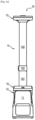
- the mast 14 has a structural role for the stability of the steaming enclosure 10, and a support role for maintaining the roof 13 at a desired distance from the base 11, the distance between the base 11 and the roof 13 possibly being different depending on the configuration of the steaming enclosure 10.
- the mast 14 can be fixed to the base 11 and to the roof 13.
- the mast 14 also has a role of guiding the translation, that is to say the sliding, of the guide piece 15 along the mast 14.
- a translation of the guide piece 15 along the mast 14 adapted to bring the guide piece 15 closer to the roof 13 causes an unfolding of the curtain 12.
- a translation of the guide piece 15 along the mast 14 adapted to bring the guide piece 15 closer to the base 11 causes a folding of the curtain 12.
- a translation of the guide piece 15 along the mast 14 causes a folding or an unfolding of the curtain 12, depending on the direction of translation of the guide piece 15.
- the de-creasing enclosure 10 therefore makes it possible to guide the translation of the guide piece 15 along the mast 14, that is to say to guide the folding and unfolding of the curtain 12.
- the user can thus easily fold or unfold the curtain 12, without having to manage the guiding of the curtain 12 himself during folding or unfolding along the mast 14, said guiding being ensured by the guiding elements 151 of the guide piece 15.
- the user can also easily attach or detach the guide piece 15 to the roof 13, by means of the fixing elements 152, 155, 156 of the guide piece 15 ensuring a removable fixing of the guide piece 15 to the roof 13.
- the guidance due to the translation of the guide piece 15 facilitates the unfolding and folding of the curtain 12, allowing a good positioning of the curtain 12 with respect to the roof 13 to easily attach the curtain 12 to the roof 13, the curtain 12 being immediately in the correct position to be attached to the roof 13 once it is unfolded.
- the user can easily modify a configuration of the steaming enclosure 10.
- Access to the steaming enclosure 10 to place the items to be steamed does not require specific means of closing and opening the curtain 12 such as a zipper.
- Folding the curtain 12 and attaching it to the roof 13 of the steaming enclosure 10 allows the user to switch to the working configuration, the open space in which the item to be steamed is positioned becoming a closed space of the steaming enclosure 10.
- the user can then launch an action cycle, for example a drying cycle, a steaming cycle, and/or a sanitizing cycle.
- the steaming enclosure 10 then performs the action cycle on the items without requiring any additional action by the user.
- a curtain axis corresponds to a direction of folding and unfolding of the curtain 12, also called vertical direction.
- the curtain axis is substantially orthogonal to the base 11 and the roof 13 of the steaming enclosure 10.
- the curtain axis passes substantially through a center of the de-creasing enclosure 10.
- top and bottom are used in reference to a position along the curtain axis, with the base 11 located at a low position and the roof 13 located at a high position.
- a radial direction is a direction perpendicular to and passing through the curtain axis.
- the terms internal and external respectively, are used in reference to the radial direction such that the inner portion or face of an element is closer to the curtain axis than the outer portion or face of the same element.
- the closed volume of the steaming enclosure 10 forms an internal volume of the steaming enclosure 10.
- the mast 14 extends substantially in the vertical direction.
- a length of the mast 14 corresponds to a dimension of the mast 14 along the curtain axis, i.e. to a dimension of the mast 14 in the direction of the greatest extent of the mast 14.
- a distance between the roof 13 and the base 11 of the steaming enclosure 10 corresponds substantially to the length of the mast 14 in the vertical direction.
- the first end 121 of the curtain 12 is adapted to be fixed to the base 11.
- the first end 121 is thus fixedly mounted relative to the base 11, and cannot be dismantled by the user.
- the textile wall 100 can substantially form a sleeve around the curtain axis, the presence of folds being limited.
- the curtain 12 When the curtain 12 is at least partially folded, the curtain 12 may be partially or completely folded back on itself.
- the curtain 12 may be at least partially placed on the base 11, if necessary inside the base 11.
- the curtain 12 may be waterproof and elastic.
- a waterproof curtain 12 makes it possible to maintain the desired humidity levels and temperature in the steaming enclosure 10 during the steaming process.
- An elastic curtain 12 makes it possible to facilitate folding or unfolding of the curtain 12, while limiting the appearance of creases.
- the curtain 12 may comprise a multi-layer textile wall comprising a first layer and a second layer, the first layer being made of a textile material comprising elastic fibers and the second layer being made of a waterproof textile material.
- the curtain 12 may comprise a textile wall and a frame.
- the frame may comprise a first curtain connector 210 provided to ensure attachment of the textile wall to the base 11 of the steaming enclosure 10 and a second curtain connector 220 provided to ensure attachment of the textile wall to the guide piece 15, as illustrated by way of non-limiting examples in Figures 10a , 10b , 12a And 12b .
- the first curtain connector 210 is attached to the first end 121 of the curtain. 12 and the second curtain connector 220 is attached to the second end 122 of the curtain 12.
- the first curtain connector 210 and/or the second curtain connector 220 may each have substantially oblong and similar shapes.
- the first curtain connector 210 and the second curtain connector 220 may be sewn over an entire perimeter of the first end 121 of the curtain 12 and the second end 122 of the curtain 12, respectively, so as to define a substantially oblong perimeter of the first end 12 of the curtain 12 and the second end 122 of the curtain 12, respectively.
- a perimeter of the unfolded curtain 12 is substantially oblong over an entire length of the curtain 12 in the vertical direction.
- the first curtain connector 210 and/or the second curtain connector 220 may be made of plastic.
- the frame may further comprise a plurality of ribs, the frame ribs being arranged at regular intervals along the textile wall.
- Each portion of the textile wall located between two frame ribs has a convex shape, such that the frame and the textile wall ensure accordion folding and unfolding of the curtain 12.
- the steaming enclosure 10 has dimensions adapted to ensure the steaming of at least one fabric article located in the closed volume of the steaming enclosure 10.
- the mast 14 can be arranged inside the closed volume of the steaming enclosure 10.
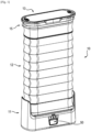
- the curtain 12 forms an external wall of the steaming enclosure 10 and has a stretched accordion shape.
- the curtain 12 has at least one fold, the curtain 12 having a folded accordion shape.
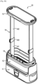
- the guide piece 15 is located at a distance from the roof 13, the guide piece 15 being brought closer to the base 11 relative to the working configuration, so as to provide between the guide piece 15 and the roof 13 the open space for receiving an article to be steamed.
- a user can place a garment in the open receiving space.
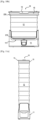
- the de-creasing enclosure 10 may further have a transport configuration, illustrated as non-limiting examples in [ Fig.10b ], in [ Fig.11b ] and in [ Fig.12b ], adapted to facilitate transport of the steaming enclosure 10 by a user.
- the steaming enclosure 10 is mobile, or portable, such that the steaming enclosure 10 can easily be assembled, disassembled and transported by the user.
- the mobile steaming enclosure 10 has in particular a reduced weight and has, in particular in the transport configuration, dimensions which allow its transport by a user. The user can thus transport the steaming enclosure 10 to different locations.
- the user can, thanks to the guidance of the guide piece 15 along the mast 14, assemble or disassemble the steaming enclosure 10 without difficulty and in a limited time.
- the mast 14 may have an adjustable length so as to maintain the roof 13 at an adjustable distance from the base 11.
- the length of the mast 14 is adjustable, a variation in the length of the mast 14 causing a corresponding variation in the distance between the roof 13 and the base 11.
- the mast 14 In the working configuration and in the access configuration, the mast 14 has a first length.
- the curtain 12 In the transport configuration, the curtain 12 is at least partially folded and the mast 14 has a second length strictly less than the first length.
- the mast 14 is therefore shorter in the transport configuration than in the working configuration or in the access configuration.
- the roof 13 is closer to the base 11 in the transport configuration than in the working configuration or in the access configuration.
- the steaming enclosure 10 has a smaller footprint in the transport configuration than in the working configuration or in the access configuration.
- the dimensions of the steaming enclosure 10 in the transport configuration are therefore smaller than in the working configuration or in the access configuration.
- the steaming enclosure 10 can thus be transported more easily when it is in the transport configuration.
- the reduced size of the steaming enclosure 10 in its transport configuration also allows space to be saved when storing the steaming enclosure 10, for example in a cupboard.
- the guide piece 15 can be fixed to the roof 13 by the fixing elements 152, 155, 156, the at least partially folded curtain 12 connecting the base 11 and the roof 13.
- the guide piece 15 can be detached from the roof 13, the curtain 12 also being able to connect the base 11 and the roof 13.
- the guide piece 15 can be located at a distance from the roof 13.
- the base 11 may be movable so as to allow movement of the steaming enclosure 10.
- the base 11 may be mounted on wheels.
- the steaming enclosure 10 can be even more easily moved by the user, regardless of the configuration of the steaming enclosure 10.
- the mast 14 may be telescopic, with multiple portions of the mast 14 fitting and sliding into each other to adjust a length of the mast 14.
- the mast 14 may comprise a first portion 141 of mast 14 fixed to the base 11, a second portion 142 of mast 14 fixed to the roof 13, and a connecting piece 143 connecting the first portion 141 of mast 14 and the second portion 142 of mast 14.
- the second portion 142 of mast 14 may be movable relative to the first portion 141 of mast 14, in particular be retractable in the first part 141 of mast 14, so as to adjust a length of the mast 14.
- a first length of the mast 14 may correspond substantially to a sum of a length of the first portion 141 of the mast 14 and a length of the second portion 142 of the mast 14.
- the first portion 141 of the mast 14 and the second portion 142 of the mast 14 may be connected and locked in position by the connecting piece 143 so as to form a substantially continuous mast 14 extending substantially in the vertical direction.
- the mast 14 makes it possible to ensure continuous guidance of the guide piece 15 during its translation along the mast 14 to unfold the curtain 12.
- the guide piece 15 can extend when the steaming enclosure 10 is in the access configuration substantially at the level of the first part 141 of the mast 14.
- the guide piece 15 must therefore be moved by the user in translation along the first part 141 of the mast 14, the junction part 143, then the second part 142 of the mast 14, in order to be fixed to the roof 13 of the steaming enclosure 10.
- a second length of the mast 14 may correspond substantially to the length of the first part 141 of the mast 14, the second part 142 of the mast 14 being for example retracted into the first part 141 of the mast 14, or folded against the first part 141 of the mast 14.
- a distance between the roof 13 and the base 11 of the steaming enclosure 10 is reduced when the mast 14 has the second length.
- the mast 14 may further comprise guide elements adapted to cooperate with the guide elements 151 of the guide part 15 so as to optimize the translational guidance of the guide part 15 along the mast 14.
- the guide elements of the mast 14 may comprise a guide rail, a guide roller 151 of the guide part 15 being adapted to roll in the guide rail. The precision of the guidance of the guide part 15 in translation along the mast 14 is thus further improved.
- the guide piece 15 is movable, and is mounted to slide in translation along the mast 14.
- the guide piece 15 can extend around the mast 14 and be arranged in contact with the mast 14.
- the guide piece 15, illustrated as a non-limiting example in [ Fig.9a ], in [ Fig.9b ] and in [ Fig.9c ], may have a substantially oblong shape.
- the guide piece 15 is attached to the second end 122 of the curtain 12. More particularly, the guide piece 15 may be attached to the second curtain connector 220 which is attached to the second end 122 of the curtain 12.
- the guide piece 15 may have a substantially oblong cylindrical shape around the curtain axis.
- the guide part 15 may have a base 154 for positioning the curtain 12, gripping elements 153, guide elements 151 and/or fixing elements 152, 155, 156.
- the base 154 for setting up the curtain 12 is adapted to ensure the fixing of the guide piece 15 to the second end 122 of the curtain 12.
- the base 154 for setting up the curtain 12 may have a substantially oblong shape.
- a perimeter of the base 154 for setting up the curtain 12 may correspond substantially to a perimeter of the second curtain connector 220.
- the curtain 12 may be attached to the curtain 12 mounting base 154, for example via the second curtain connector 220, the second curtain connector 220 being attached to both the second end 122 of the curtain 12 and to the curtain 12 mounting base 154.
- the base 11 of the steaming enclosure 10 may have a substantially oblong shape.
- a perimeter of the base 11 may correspond substantially to a perimeter of the first curtain connector 210.
- the curtain 12 may be attached to the base 11 via the first curtain connector 210, the first curtain connector 210 being attached to both the first end 121 of the curtain 12 and the base 11.
- the first curtain connector 210 may be screwed to a bottom 111 of the base 11 of the steaming enclosure 10.
- the gripping elements 153 of the guide piece 15 may comprise a handle.
- the user grasps the handle 153 to slide the guide piece 15 along the mast 14 in order to bring it closer to the base 11 or the roof 13 of the steaming enclosure 10.
- the handle 153 may be formed by an external projection of the base 11 of the guide piece 15.
- the guide piece 15 may comprise two handles 153 arranged on either side of the oblong base 154, on each side of the oblong base 154. Thus, the user can grasp the two handles 153 at the same time to move the guide piece 15, which makes guiding easier.
- the guide elements 151 of the guide part 15 are adapted to extend into contact with the mast 14, more particularly into contact with an external face of the mast 14, so as to provide translational guidance of the guide part 15 along the mast 14.
- the guide elements 151 may be mounted on the substantially oblong base 154 of the guide part 15, for example be mounted in the substantially oblong base 154 so as to protrude at least partially in a more internal position than the base 154.
- the guide elements 151 of the guide part 15 may comprise at least one guide roller adapted to roll along the mast 14 during translational movement of the guide part 15 along the mast 14.
- the guide roller 151 may be in the form of a disk or a wheel. The guide roller 151 makes it possible to reduce friction during the translational movement of the guide part 15 along the mast 14.
- the smoothing enclosure 10 may comprise two substantially parallel masts 14 arranged on each side of the base 11, for example on either side of the oblong base 11.
- the guide elements 151 are adapted to provide translational guidance of the guide part 15 along each of the two masts 14.
- the guide elements 151 may comprise at least two guide rollers arranged on either side of the oblong base 154, on each side of the oblong base 154.
- Each guide roller 151 is in contact with one of the two masts 14 of the steaming enclosure 10. This configuration allows even more efficient and precise guidance of the translation of the guide part 15 along the mast 14.
- the guide elements 151 can comprise two pairs of guide rollers 151 arranged on either side of the oblong base 154, each pair of guide rollers 151 being in contact with one of the two masts 14 of the steaming enclosure 10.
- the fixing elements 152, 155, 156 of the guide piece 15 are adapted to removably fix the guide piece 15 to the roof 13.
- the roof 13 may comprise fixing elements adapted to cooperate with the fixing elements 152, 155, 156 of the guide piece 15 to the roof 13 so as to ensure a removably fixing of the guide piece 15 to the roof 13.
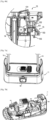
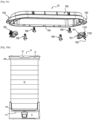
- the [ Fig.6a ] and the [ Fig.6b ] illustrate a non-limiting example of a cooperation between the guide piece 15 and the roof 13 so as to fix, or attach, the guide piece 15 to the roof 13.
- the fixing elements 152, 155, 156 of the guide piece 15 may comprise a clipping hook 1551 of the guide piece 15 to the roof 13.
- the fixing of the guide piece 15 to the roof 13 is then carried out by clipping the guide piece 15 onto the roof 13.
- clipping makes it possible to attach the curtain 12 to the roof 13 automatically when the curtain 12 reaches the fully unfolded position, that is to say without requiring any specific action on the part of the user.
- the clipping hook 1551 is automatically in position to be clipped to the roof 13 due to the guiding of the unfolding of the curtain 12 by the guiding elements 151 of the guiding piece 15: when the guiding piece 15 reaches the level of the roof 13 of the steaming enclosure 10, the clipping hook 1551 engages with the roof 13 to lock the guiding piece 15 relative to the roof 13, without requiring any additional action by the user.
- the clipping hook 1551 can be attached and fixed to the base 154 for placing the curtain 12 of the guide piece 15, in a more internal position than the handle 153.
- the clipping hook 1551 can project towards the roof 13, that is to say upwards, relative to the base 154 for placing the curtain 12 of the guide piece 15, so that the clipping hook 1551 comes into contact with the roof 13 of the steaming enclosure 10 when the curtain 12 is unfolded.
- the fixing elements 152, 155, 156 of the guide piece 15 may comprise a lever 155 comprising a first end 1551 and a second end 1552 opposite the first end 1551.
- the first end 1551 of the lever 155 forms the clipping hook of the guide piece 15 to the roof 13.
- the second end 1552 of the lever 155 is adapted to be actuated in pivoting so as to unclip the guide piece 15 from the roof 13.
- the second end 1552 of the lever 155 can be actuated in pivoting by the user when the guide piece 15 is attached to the roof 13, so as to detach the clipping hook 1151 formed by the first end 1551 from the roof 13.
- the second end 1552 of the lever 155 projects toward the base 11, i.e. downwards, relative to the base 154 of the guide piece 15, so as to be able to be grasped by the user when the guide piece 15 is fixed to the roof 13 by the clipping hook forming the first end 1551 of the lever 155.
- the user can actuate the second end 1552 of the lever 155 so as to pivot the lever 155 to disengage the first end 1551 of the lever from the roof 13 and thus detach the guide piece 15 from the roof 13.
- the fixing elements 152, 155, 156 of the guide piece 15 may comprise a frustoconical wall 152.
- the roof 13 then comprises a cavity adapted to receive the frustoconical wall 152 when the guide piece 15 is fixed to the roof 13.
- the cavity of the roof 13 may extend substantially downwards relative to the roof 13.
- the frustoconical wall 152 makes it possible to further improve the precision of the guidance of the unfolding of the curtain 12, in particular makes it possible to precisely position the guide piece 15 relative to the roof 13 at the end of travel of the movement of the guide piece 15 towards the roof 13, when the steaming enclosure 10 is moved to the working configuration, so as to make it possible to easily attach the guide piece 15 to the roof 13.
- the cavity of the roof 13 may have a shape and dimensions substantially complementary to said frustoconical wall 152 of the guide piece 15: for example, a shape and dimensions of an inner surface of the roof cavity 13 may substantially correspond to a shape and dimensions of an outer surface of the frustoconical wall 152 of the guide piece 15.
- the frustoconical wall 152 may be attached and fixed to the base 154 for placing the curtain 12, or be formed in one piece with the base 154.
- the frustoconical wall 152 may extend toward the roof 13, i.e. upwards, relative to the base 154, such that the frustoconical wall 152 comes into contact with the roof 13 of the steaming enclosure 10, in particular is inserted into the roof cavity 13, when the curtain 12 is unfolded.
- the fixing elements 152, 155, 156 of the guide piece 15 may comprise clips 156 for fixing the curtain 12 attached and fixed along a perimeter of the base 154 for setting up the curtain 12.
- the fixing clips 156 may be elastic tabs.
- four fixing clips 156 may be distributed along the base 154 for setting up the curtain.
- the clips 156 of fixing cooperate when unfolding the curtain 12 with fixing elements of the roof 13, for example can be inserted into respective housings of the roof 13 when the curtain 12 is unfolded.
- the fixing clips 156 contribute to fixing the curtain 12 to the roof 13 of the steaming enclosure 10 and to maintaining the steaming enclosure 10 in the working configuration.
- the roof 13 may include a seal 131, an example of which is visible in the Figures 5, 6a And 6b , adapted to ensure the seal between the guide piece 15 and the roof 13 when the guide piece 15 is fixed to the roof 13.
- the seal 131 makes it possible to ensure the steam seal, so that when the steaming enclosure 10 is in the working configuration and performs a steaming cycle, the steam injected into the closed volume of the steaming enclosure 10 does not escape from the steaming enclosure 10.
- the seal 131 may be arranged along an entire circumference of the guide piece 15.
- the fixing elements 152, 155, 156 of the guide piece 15 bear on the seal 131 when the guide piece 15 is fixed to the roof 13, so as to ensure sealing.
- the steam generation and injection device 200 and the hot air blowing drying device 100 can be integrated into the base 11 of the steaming enclosure 10, as illustrated by way of non-limiting example in Figures 7a and 7b .
- the steam generation and injection device 200 and the hot air blowing drying device 100 may comprise at least one pipe opening from the base 11 of the steaming enclosure 10 into the volume for receiving the article to be steamed, at the base 11 of the steaming enclosure 10.
- the steam and hot air generated are injected into the steaming enclosure 10 at the base 11 of the steaming enclosure 10, and rise towards the roof 13 of the steaming enclosure 10 through the article(s) to be steamed. This makes it possible to ensure effective steaming of the article placed in the steaming enclosure 10.
- the hot air blowing drying device 100 may comprise a fan associated with a heating resistor. The air is heated by the heating resistor and ventilated by the fan to be injected inside the steaming enclosure 10.
- the steaming enclosure 10 may further comprise a device for cooling by blowing cold air, adapted to cool the fabric article(s) placed in the steaming enclosure 10 after its/their steaming.
- the device for cooling by blowing cold air may correspond to the device for drying by blowing hot air 200.
- the device may be configured to blow hot air, then to blow cold air once the step of drying by blowing hot air is complete.
- the steaming enclosure 10 may comprise at least one garment placement element adapted to ensure placement and maintenance of the garment during a steaming cycle.
- the user prepares the item to be steamed by placing the item to be steamed in the steaming enclosure 10, in particular on a garment placement element.
- At least one garment-placing element can be attached and removably fixed to the roof 13 of the steaming enclosure 10.
- a rod, a hanger 40 and/or at least one article-fixing clip 41 can be attached and removably fixed to the roof 13 of the steaming enclosure 10.
- the [ Fig.5 ] illustrates a non-limiting example of a hanger 40 and a clamp 41 removably attached to the roof 13 of the steaming enclosure 10.
- At least one garment fitting element may comprise at least one weighted clamp 30, as illustrated by way of non-limiting example in Figures 14a to 14c .
- the user can then hang the at least one weighted clip 30 on the fabric article and place the fabric article in the steaming enclosure 10, before or after having hung said weighted clip 30, in particular on a hanger 40 of the steaming enclosure 10.
- the weighted clip 30 is preferably hung on a lower part of the fabric article, for example at the base 11 of the garment, an upper part of the fabric article being placed on the hanger 40 of the steaming enclosure 10.
- Several weighted clips 30 can be hung on the fabric article.
- weighted clips 30 can be hung on each sleeve of the shirt and on the base 11 of the shirt. If the fabric article is a pair of pants, weighted clips 30 can be hung at the bottom of each of the pants legs.
- the weighted clamp 30 may have different weights and/or dimensions.
- the weighted clamp 30 may have a width of between 100 mm and 200 mm, preferably a width of about 150 mm.
- the weighted clamp 30 may have a weight of between 300 g and 1 kg, preferably about 400 g.
- Fig.14a illustrates an example of a weighted clamp 30 30 having dimensions and a weight greater than the 30 weighted clamp illustrated in [ Fig.14b ].
- the dimensions of the weighted clamp 30 are adapted according to the fabric article on which the weighted clamp 30 is intended to be attached. This makes it easier to attach the weighted clamp 30 to the fabric article.
- the weight of the weighted clamp 30 is adapted to adjust the tension of the fibers of the fabric article, thereby further improving the efficiency of the wrinkle removal process.
- One or more openings may be formed in the hanger 40, as illustrated by way of non-limiting example in [ Fig.15 ].
- the steam and/or hot air injected into the steaming enclosure 10 can pass through the openings of the hanger 40, which makes it possible to further increase the efficiency of the steaming process.
- the hanger 40 may have a minimum width of 450 mm, and/or a minimum thickness of 40 mm.
- the hanger 40 may have rounded edges to avoid marking the articles placed on the hanger 40.
- the hanger 40 can be placed on the rod, or on a hook fixed to the roof 13 of the steaming enclosure 10.
- the base 11 may comprise at least one garment-placing element, such as a perforated grid 60.
- the perforated grid 60 as illustrated by way of non-limiting examples in Figures 16a And 16b , is adapted to be placed in contact with the base 11 of the steaming enclosure 10, on the base 11 of the steaming enclosure 10.
- the user can place a fabric article on the perforated grid 60.
- the perforated grid 60 forms a shelf adapted to receive a fabric article to be steamed.
- the perforated grid 60 can be a removable grid formed of two grid halves. The two grid halves are arranged in contact with each other and in contact with the base 11 of the steaming enclosure 10, so as to form a perforated grid 60 which covers the base 11 of the steaming enclosure 10.
- the perforated grid 60 When the steam generation and injection device and the hot air blowing drying device are integrated into the base 11 of the steaming enclosure 10, the perforated grid 60 is positioned close to the steam and hot air outlets of the base 11 of the steaming enclosure 10. Thus, the temperatures are particularly high for the articles placed on the perforated grid 60.
- the perforated grid 60 therefore allows particularly effective steaming and, where appropriate, sanitization of the articles placed on the perforated grid 60. For example, stuffed animals or shoes can be placed on the perforated grid 60.
- the user can for example unclip the clipping hook 1551 from the guide piece 15 of the roof 13 so as to detach the guide piece 15 from the roof 13.
- Attaching the fasteners 152, 155, 156 of the guide piece 15 to the roof 13 can be performed without requiring any particular action by the user when the curtain 12 reaches the fully extended position. More particularly, when the guide piece 15 reaches the level of the roof 13 of the steaming enclosure 10, the clipping hook 1551 can engage with the roof 13 to lock the guide piece 15 relative to the roof 13, without requiring any additional action by the user.
- a method of using the steaming enclosure 10 may further comprise a step of adjusting a length of the mast 14.
- the length of the mast 14 may be adjusted by the user. For example, when the steaming enclosure 10 is in the access configuration, the user may retract the second portion 142 of the mast 14 inside the first portion 141 of the mast to change the mast 14 from a first length to a second length strictly less than the first length. Conversely, the user may deploy the second portion 142 of the mast 14 outside the first portion 141 of the mast 14 to change the mast 14 from the first length to the second length.
- a method of using the steaming enclosure 10 may further comprise a step of, when the steaming enclosure 10 is in the access configuration, placing an article in or removing an article from the open receiving space provided between the guide piece 15 and the roof 13. The user thereby positions one or more articles to be steamed in the open receiving space.
- the open receiving space will become the closed volume of the steaming enclosure 10 when the steaming enclosure 10 is in the working configuration.
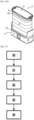
- the method may further comprise a step E4 of cooling the article by blowing cold air into the steaming enclosure 10, the cooling step E4 being carried out following the drying step by blowing hot air E3.
- the method may further comprise a prior step E0 of parameterization by a user of the steaming enclosure 10, by means of a parameterization unit 50 of the steaming enclosure 10.
Landscapes
- Engineering & Computer Science (AREA)
- Textile Engineering (AREA)
- Curtains And Furnishings For Windows Or Doors (AREA)
- Irons (AREA)
- Apparatus For Radiation Diagnosis (AREA)
Claims (17)
- Glättkammer (10), umfassend:- eine Basis (11);- ein Dach (13), das der Basis (11) zugewandt ist;- einen Mast (14), der sich zwischen der Basis (11) und dem Dach (13) erstreckt, um das Dach (13) in Abstand von der Basis (11) zu halten;- einen auseinanderfaltbaren Vorhang (12), der dazu vorgesehen ist, sich zwischen der Basis (11) und dem Dach (13) zu erstrecken, wobei der Vorhang (12) ein erstes Ende (121), das geeignet ist, an der Basis (11) befestigt zu werden, und ein zweites Ende (122) umfasst, das dem ersten Ende (121) gegenüberliegt; und- ein Führungsteil (15), das am zweiten Ende (122) des Vorhangs (12) befestigt ist, wobei das Führungsteil (15) Befestigungselemente (152, 155, 156) umfasst, die dazu vorgesehen sind, eine abnehmbare Befestigung des Führungsteils (15) am Dach (13) sicherzustellen, wobei die Glättkammer (10) aufweist:- eine Arbeitskonfiguration, in der das Führungsteil (15) über die Befestigungselemente (152, 155, 156) am Dach (13) befestigt ist und der Vorhang (12) auseinandergefaltet ist, um das Dach (13) und die Basis (11) zu verbinden, wobei die Basis (11) , das Dach (13) und der Vorhang (12) zusammen ein geschlossenes Volumen der Glättkammer (10) begrenzen; und- eine Zugangskonfiguration, in der das Führungsteil (15) vom Dach (13) gelöst ist und der Vorhang (12) mindestens teilweise zusammengefaltet ist, um zwischen dem Führungsteil (15) und dem Dach (13) einen offenen Raum zum Aufnehmen eines zu glättenden Artikels auszugestalten, dadurch gekennzeichnet, dass das Führungsteil (15) Führungselemente (151) umfasst, die dazu vorgesehen sind, eine Verschiebung des Führungsteils (15) entlang des Mastes (14) zu führen.
- Glättkammer (10) nach Anspruch 1, wobei der Mast (14) eine verstellbare Länge aufweist, um das Dach (13) in einem verstellbaren Abstand von der Basis (11) zu halten, wobei in der Arbeitskonfiguration und in der Zugangskonfiguration der Mast (14) eine erste Länge aufweist, und wobei die Glättkammer (10) weiter eine Transportkonfiguration aufweist, in der der Vorhang (12) mindestens teilweise zusammengefaltet ist und der Mast (14) eine zweite Länge aufweist, die strikt kleiner ist als die erste Länge.
- Glättkammer (10) nach Anspruch 2, wobei der Mast (14) teleskopierbar ist.
- Glättkammer (10) nach einem der Ansprüche 1 bis 3, wobei der Vorhang (12) eine mehrschichtige Textilwand (100) umfasst, die eine erste Schicht und eine zweite Schicht umfasst, wobei die erste Schicht aus einem Textilmaterial hergestellt ist, das elastische Fasern umfasst, und wobei die zweite Schicht aus einem dichten Textilmaterial hergestellt ist.
- Glättkammer (10) nach einem der Ansprüche 1 bis 4, wobei der Vorhang (12) eine Textilwand (100) und eine Armierung umfasst, die eine Vielzahl von Stegen umfasst, wobei die Armierungsstege in regelmäßigem Intervall entlang der Textilwand (100) angeordnet sind, und wobei jeder Abschnitt der Textilwand (100), der sich zwischen zwei Armierungsstegen befindet, eine konvexe Form aufweist, sodass die Armierung und die Textilwand (100) ein ziehharmonikaartiges Zusammenfalten und Auseinanderfalten des Vorhangs sicherstellen.
- Glättkammer (10) nach einem der Ansprüche 1 bis 5, wobei das Führungsteil (15) eine im Wesentlichen längliche Form aufweist, und wobei das Führungsteil (15) am zweiten Ende (122) des Vorhangs (12) befestigt ist.
- Glättkammer (10) nach einem der Ansprüche 1 bis 6, wobei die Führungselemente (151) des Führungsteils (15) mindestens eine Führungsrolle umfassen, die geeignet ist, entlang des Mastes (14) zu rollen.
- Glättkammer (10) nach einem der Ansprüche 1 bis 7, wobei die Befestigungselemente (152, 155, 156) des Führungsteils (15) einen Haken (1551) zum Einclipsen des Führungsteils (15) am Dach (13) umfassen.
- Glättkammer (10) nach Anspruch 8, wobei die Befestigungselemente (152, 155, 156) des Führungsteils (15) einen Hebel (155) umfassen, der ein erstes Ende (1551) und ein dem ersten Ende (1551) gegenüberliegendes zweites Ende (1552) umfasst, wobei das erste Ende (1551) des Hebels (155) den Haken zum Einclipsen des Führungsteils (15) am Dach (13) bildet, und wobei das zweite Ende (1552) des Hebels (155) geeignet ist, schwenkend betätigt zu werden, um den Haken (1551) zum Einclipsen des Führungsteils (15) vom Dach (13) auszuclipsen.
- Glättkammer (10) nach einem der Ansprüche 1 bis 9, wobei die Befestigungselemente (152, 155, 156) des Führungsteils (15) eine kegelstumpfförmige Wand (152) umfassen und das Dach (13) einen Hohlraum umfasst, der geeignet ist, die kegelstumpfförmige Wand (152) aufzunehmen, wenn das Führungsteil (15) am Dach (13) befestigt ist.
- Glättkammer (10) nach einem der Ansprüche 1 bis 10, wobei das Dach (13) eine Dichtung (131) umfasst, die geeignet ist, die Dichtigkeit zwischen dem Führungsteil (15) und dem Dach (13) sicherzustellen, wenn das Führungsteil (15) am Dach (13) befestigt ist.
- Glättkammer (10) nach einem der Ansprüche 1 bis 11, die zwei im Wesentlichen parallele Masten (14) umfasst, die beiderseits der Basis (11) angeordnet sind, und wobei die Führungselemente (151) geeignet sind, eine Verschiebeführung des Führungsteils (15) entlang jedes der zwei Masten (14) sicherzustellen.
- Glättkammer (10) nach einem der Ansprüche 1 bis 12, wobei in der Zugangskonfiguration der Vorhang (12) mindestens teilweise im Inneren der Basis (11) zusammengefaltet ist.
- Verfahren zur Verwendung einer Glättkammer (10) nach einem der Ansprüche 1 bis 13, das mindestens die folgenden Schritte umfasst, um von der Arbeitskonfiguration in die Zugangskonfiguration zu gelangen:- Lösen der Befestigungselemente (152, 155, 156) des Führungsteils (15) vom Dach (13); und- Verschiebebewegen des Führungsteils (15) entlang des Mastes (14), um den Vorhang (12) zusammenzufalten, wobei die Verschiebung über die Führungselemente (151) geführt wird.
- Verfahren zur Verwendung einer Glättkammer (10) nach einem der Ansprüche 1 bis 13, das mindestens die folgenden Schritte umfasst, um von der Zugangskonfiguration in die Arbeitskonfiguration zu gelangen:- Verschiebebewegen des Führungsteils (15) entlang des Mastes (14), um den Vorhang (12) auseinanderzufalten, wobei die Verschiebung über die Führungselemente (151) geführt wird; und- Befestigen der Befestigungselemente (152, 155, 156) des Führungsteils (15) am Dach (13).
- Verfahren nach Anspruch 14 oder Anspruch 15, das weiter einen Schritt umfasst, der darin besteht, eine Länge des Mastes (14) zu verstellen.
- Verfahren nach einem der Ansprüche 14 bis 16, das weiter einen Schritt umfasst, der darin besteht, wenn sich die Glättkammer (10) in der Zugangskonfiguration befindet, einen Artikel in dem offenen Aufnahmeraum, der zwischen dem Führungsteil (15) und dem Dach (13) ausgestaltet ist, zu platzieren oder einen Artikel aus diesem herauszunehmen.
Applications Claiming Priority (2)
| Application Number | Priority Date | Filing Date | Title |
|---|---|---|---|
| FR2105816A FR3123664B1 (fr) | 2021-06-02 | 2021-06-02 | Enceinte de defroissage pliable avec guidage du pliage et du depliage |
| PCT/EP2022/063933 WO2022253618A1 (fr) | 2021-06-02 | 2022-05-23 | Enceinte de defroissage pliable avec guidage du pliage et du depliage |
Publications (3)
| Publication Number | Publication Date |
|---|---|
| EP4347940A1 EP4347940A1 (de) | 2024-04-10 |
| EP4347940B1 true EP4347940B1 (de) | 2025-02-19 |
| EP4347940C0 EP4347940C0 (de) | 2025-02-19 |
Family
ID=76523200
Family Applications (1)
| Application Number | Title | Priority Date | Filing Date |
|---|---|---|---|
| EP22730225.4A Active EP4347940B1 (de) | 2021-06-02 | 2022-05-23 | Faltbares faltenentfernungsgehäuse mit geführter faltung und entfaltung und verfahren zu seiner verwendung |
Country Status (4)
| Country | Link |
|---|---|
| EP (1) | EP4347940B1 (de) |
| CN (1) | CN117480294B (de) |
| FR (1) | FR3123664B1 (de) |
| WO (1) | WO2022253618A1 (de) |
Family Cites Families (18)
| Publication number | Priority date | Publication date | Assignee | Title |
|---|---|---|---|---|
| GB515875A (en) * | 1938-07-06 | 1939-12-15 | Charles Willber | Improvements in or relating to clothes drying and airing cabinets |
| GB1414041A (en) * | 1973-03-06 | 1975-11-12 | Parlour N S | Apparatus for treating laundry articles |
| FR2298636A1 (fr) * | 1975-01-23 | 1976-08-20 | Alby Albert | Ensemble util |
| FR2484194A1 (fr) * | 1980-06-11 | 1981-12-18 | Maison Occitane Sa | Rideau isolant de serre a depliage et repliage automatiques |
| ATE239815T1 (de) | 1999-06-04 | 2003-05-15 | Whirlpool Co | Vorrichtung zum reinigen und zum auffrischen von textilien |
| EP1215330B1 (de) | 2000-12-14 | 2005-03-23 | Whirlpool Corporation | Vorrichtung zum Reinigen und zum Auffrischen von Textilien mit einer eingebauten Betriebsanzeige |
| US7444840B2 (en) | 2003-04-23 | 2008-11-04 | Whirlpool Corporation | Air circulation system in a clothes refresher |
| US8141269B2 (en) | 2004-05-24 | 2012-03-27 | Whirlpool Corporation | Expandable/collapsible enclosure for a clothes refresher |
| KR100813048B1 (ko) | 2005-02-28 | 2008-03-14 | 엘지전자 주식회사 | 리프레쉬 장치 |
| KR100808177B1 (ko) * | 2005-04-22 | 2008-02-29 | 엘지전자 주식회사 | 리프레쉬 장치 |
| US8464562B1 (en) * | 2012-04-02 | 2013-06-18 | Michael G. Colburn | Garment steamer |
| RU2652970C2 (ru) * | 2012-08-21 | 2018-05-03 | Конинклейке Филипс Н.В. | Камера для отпаривателя |
| US10773881B2 (en) * | 2015-10-05 | 2020-09-15 | Advanced Composite Structures, Llc | Air cargo container and curtain for the same |
| KR20170141489A (ko) | 2016-06-15 | 2017-12-26 | 엘지전자 주식회사 | 의류 처리 장치 |
| CN206692923U (zh) * | 2017-03-09 | 2017-12-01 | 桂林电子科技大学 | 干衣机 |
| CN108330663A (zh) * | 2018-04-17 | 2018-07-27 | 桂林电子科技大学 | 一种简易可调家用型干衣机 |
| KR102132154B1 (ko) * | 2018-11-14 | 2020-07-09 | (주)동양이지텍 | 방수천 커버의 교환과 세탁이 용이한 의류 관리기 |
| CN211713463U (zh) * | 2019-09-25 | 2020-10-20 | 青岛星河针织品有限公司 | 一种便于携带的内衣烘干装置 |
-
2021
- 2021-06-02 FR FR2105816A patent/FR3123664B1/fr active Active
-
2022
- 2022-05-23 CN CN202280039146.XA patent/CN117480294B/zh active Active
- 2022-05-23 WO PCT/EP2022/063933 patent/WO2022253618A1/fr not_active Ceased
- 2022-05-23 EP EP22730225.4A patent/EP4347940B1/de active Active
Also Published As
| Publication number | Publication date |
|---|---|
| FR3123664A1 (fr) | 2022-12-09 |
| WO2022253618A1 (fr) | 2022-12-08 |
| EP4347940A1 (de) | 2024-04-10 |
| CN117480294B (zh) | 2026-04-14 |
| CN117480294A (zh) | 2024-01-30 |
| EP4347940C0 (de) | 2025-02-19 |
| FR3123664B1 (fr) | 2023-04-28 |
Similar Documents
| Publication | Publication Date | Title |
|---|---|---|
| US10117513B1 (en) | Portable chafing and serving table | |
| CN104768431B (zh) | 脚架 | |
| CA2621216C (fr) | Capot de nacelle pour turboreacteur et nacelle comportant au moins un tel capot | |
| EP2881513B1 (de) | Reise-Trockenständer zum Wäschetrocknen | |
| WO2012076772A1 (fr) | Dispositif de repassage escamotable à centrale vapeur | |
| CA2785162A1 (en) | Portable cooking device | |
| WO2022253618A1 (fr) | Enceinte de defroissage pliable avec guidage du pliage et du depliage | |
| EP0771229B1 (de) | Faltbare hintergrundstruktur | |
| US20140109433A1 (en) | Collapsible Clothes Hanging and Drying Apparatus | |
| KR100732607B1 (ko) | 절첩식 빨래 건조대 | |
| BE665231A (de) | ||
| FR2950239A1 (fr) | Grille-pain a porte laterale pivotante | |
| US6301800B1 (en) | Method of use for inverted bonnet hair dryer | |
| US2004035A (en) | Convertible and portable wardrobe and clothes drier | |
| CN202148438U (zh) | 一种用于电暖器的开合式衣架 | |
| KR200483979Y1 (ko) | 애완동물용 드라이 룸 | |
| KR101440267B1 (ko) | 빨래건조대 | |
| EP0837175A1 (de) | Wäschetrockner | |
| FR3063964A1 (fr) | Chariot de courses pour poussette | |
| KR101487428B1 (ko) | 노출식 빨래 건조대 | |
| WO2018130844A1 (en) | A drier system | |
| EP4347942A1 (de) | Faltbare faltenentfernungshülle mit einem mehrschichtigen vorhang | |
| GB2292310A (en) | Portable clothes airer | |
| KR200480670Y1 (ko) | 사다리 일체형 쇼핑카트 | |
| KR102945465B1 (ko) | 접이식 빨래건조대 |
Legal Events
| Date | Code | Title | Description |
|---|---|---|---|
| STAA | Information on the status of an ep patent application or granted ep patent |
Free format text: STATUS: UNKNOWN |
|
| STAA | Information on the status of an ep patent application or granted ep patent |
Free format text: STATUS: THE INTERNATIONAL PUBLICATION HAS BEEN MADE |
|
| PUAI | Public reference made under article 153(3) epc to a published international application that has entered the european phase |
Free format text: ORIGINAL CODE: 0009012 |
|
| STAA | Information on the status of an ep patent application or granted ep patent |
Free format text: STATUS: REQUEST FOR EXAMINATION WAS MADE |
|
| 17P | Request for examination filed |
Effective date: 20231213 |
|
| AK | Designated contracting states |
Kind code of ref document: A1 Designated state(s): AL AT BE BG CH CY CZ DE DK EE ES FI FR GB GR HR HU IE IS IT LI LT LU LV MC MK MT NL NO PL PT RO RS SE SI SK SM TR |
|
| DAV | Request for validation of the european patent (deleted) | ||
| DAX | Request for extension of the european patent (deleted) | ||
| GRAP | Despatch of communication of intention to grant a patent |
Free format text: ORIGINAL CODE: EPIDOSNIGR1 |
|
| STAA | Information on the status of an ep patent application or granted ep patent |
Free format text: STATUS: GRANT OF PATENT IS INTENDED |
|
| INTG | Intention to grant announced |
Effective date: 20241008 |
|
| GRAS | Grant fee paid |
Free format text: ORIGINAL CODE: EPIDOSNIGR3 |
|
| GRAA | (expected) grant |
Free format text: ORIGINAL CODE: 0009210 |
|
| STAA | Information on the status of an ep patent application or granted ep patent |
Free format text: STATUS: THE PATENT HAS BEEN GRANTED |
|
| AK | Designated contracting states |
Kind code of ref document: B1 Designated state(s): AL AT BE BG CH CY CZ DE DK EE ES FI FR GB GR HR HU IE IS IT LI LT LU LV MC MK MT NL NO PL PT RO RS SE SI SK SM TR |
|
| REG | Reference to a national code |
Ref country code: GB Ref legal event code: FG4D Free format text: NOT ENGLISH |
|
| REG | Reference to a national code |
Ref country code: CH Ref legal event code: EP |
|
| REG | Reference to a national code |
Ref country code: IE Ref legal event code: FG4D Free format text: LANGUAGE OF EP DOCUMENT: FRENCH |
|
| REG | Reference to a national code |
Ref country code: DE Ref legal event code: R096 Ref document number: 602022010880 Country of ref document: DE |
|
| U01 | Request for unitary effect filed |
Effective date: 20250227 |
|
| U07 | Unitary effect registered |
Designated state(s): AT BE BG DE DK EE FI FR IT LT LU LV MT NL PT RO SE SI Effective date: 20250307 |
|
| U20 | Renewal fee for the european patent with unitary effect paid |
Year of fee payment: 4 Effective date: 20250425 |
|
| PG25 | Lapsed in a contracting state [announced via postgrant information from national office to epo] |
Ref country code: RS Free format text: LAPSE BECAUSE OF FAILURE TO SUBMIT A TRANSLATION OF THE DESCRIPTION OR TO PAY THE FEE WITHIN THE PRESCRIBED TIME-LIMIT Effective date: 20250519 |
|
| PG25 | Lapsed in a contracting state [announced via postgrant information from national office to epo] |
Ref country code: PL Free format text: LAPSE BECAUSE OF FAILURE TO SUBMIT A TRANSLATION OF THE DESCRIPTION OR TO PAY THE FEE WITHIN THE PRESCRIBED TIME-LIMIT Effective date: 20250219 |
|
| PG25 | Lapsed in a contracting state [announced via postgrant information from national office to epo] |
Ref country code: ES Free format text: LAPSE BECAUSE OF FAILURE TO SUBMIT A TRANSLATION OF THE DESCRIPTION OR TO PAY THE FEE WITHIN THE PRESCRIBED TIME-LIMIT Effective date: 20250219 |
|
| PG25 | Lapsed in a contracting state [announced via postgrant information from national office to epo] |
Ref country code: IS Free format text: LAPSE BECAUSE OF FAILURE TO SUBMIT A TRANSLATION OF THE DESCRIPTION OR TO PAY THE FEE WITHIN THE PRESCRIBED TIME-LIMIT Effective date: 20250619 Ref country code: NO Free format text: LAPSE BECAUSE OF FAILURE TO SUBMIT A TRANSLATION OF THE DESCRIPTION OR TO PAY THE FEE WITHIN THE PRESCRIBED TIME-LIMIT Effective date: 20250519 |
|
| PG25 | Lapsed in a contracting state [announced via postgrant information from national office to epo] |
Ref country code: HR Free format text: LAPSE BECAUSE OF FAILURE TO SUBMIT A TRANSLATION OF THE DESCRIPTION OR TO PAY THE FEE WITHIN THE PRESCRIBED TIME-LIMIT Effective date: 20250219 |
|
| PG25 | Lapsed in a contracting state [announced via postgrant information from national office to epo] |
Ref country code: GR Free format text: LAPSE BECAUSE OF FAILURE TO SUBMIT A TRANSLATION OF THE DESCRIPTION OR TO PAY THE FEE WITHIN THE PRESCRIBED TIME-LIMIT Effective date: 20250520 |
|
| PG25 | Lapsed in a contracting state [announced via postgrant information from national office to epo] |
Ref country code: SM Free format text: LAPSE BECAUSE OF FAILURE TO SUBMIT A TRANSLATION OF THE DESCRIPTION OR TO PAY THE FEE WITHIN THE PRESCRIBED TIME-LIMIT Effective date: 20250219 |
|
| PG25 | Lapsed in a contracting state [announced via postgrant information from national office to epo] |
Ref country code: CZ Free format text: LAPSE BECAUSE OF FAILURE TO SUBMIT A TRANSLATION OF THE DESCRIPTION OR TO PAY THE FEE WITHIN THE PRESCRIBED TIME-LIMIT Effective date: 20250219 |
|
| PG25 | Lapsed in a contracting state [announced via postgrant information from national office to epo] |
Ref country code: SK Free format text: LAPSE BECAUSE OF FAILURE TO SUBMIT A TRANSLATION OF THE DESCRIPTION OR TO PAY THE FEE WITHIN THE PRESCRIBED TIME-LIMIT Effective date: 20250219 |
|
| REG | Reference to a national code |
Ref country code: CH Ref legal event code: H13 Free format text: ST27 STATUS EVENT CODE: U-0-0-H10-H13 (AS PROVIDED BY THE NATIONAL OFFICE) Effective date: 20251223 |
|
| PLBE | No opposition filed within time limit |
Free format text: ORIGINAL CODE: 0009261 |
|
| STAA | Information on the status of an ep patent application or granted ep patent |
Free format text: STATUS: NO OPPOSITION FILED WITHIN TIME LIMIT |
|
| PG25 | Lapsed in a contracting state [announced via postgrant information from national office to epo] |
Ref country code: CH Free format text: LAPSE BECAUSE OF NON-PAYMENT OF DUE FEES Effective date: 20250531 |
|
| 26N | No opposition filed |
Effective date: 20251120 |
|
| PG25 | Lapsed in a contracting state [announced via postgrant information from national office to epo] |
Ref country code: MC Free format text: LAPSE BECAUSE OF FAILURE TO SUBMIT A TRANSLATION OF THE DESCRIPTION OR TO PAY THE FEE WITHIN THE PRESCRIBED TIME-LIMIT Effective date: 20250219 |
|
| PG25 | Lapsed in a contracting state [announced via postgrant information from national office to epo] |
Ref country code: IE Free format text: LAPSE BECAUSE OF NON-PAYMENT OF DUE FEES Effective date: 20250523 |