EP4348096B1 - Agencement et procédé dans un système d'alimentation en carburant hydrogène liquide - Google Patents
Agencement et procédé dans un système d'alimentation en carburant hydrogène liquide Download PDFInfo
- Publication number
- EP4348096B1 EP4348096B1 EP21731720.5A EP21731720A EP4348096B1 EP 4348096 B1 EP4348096 B1 EP 4348096B1 EP 21731720 A EP21731720 A EP 21731720A EP 4348096 B1 EP4348096 B1 EP 4348096B1
- Authority
- EP
- European Patent Office
- Prior art keywords
- inlet line
- tank
- liquid hydrogen
- gas
- supply system
- Prior art date
- Legal status (The legal status is an assumption and is not a legal conclusion. Google has not performed a legal analysis and makes no representation as to the accuracy of the status listed.)
- Active
Links
Images

Classifications
-
- B—PERFORMING OPERATIONS; TRANSPORTING
- B63—SHIPS OR OTHER WATERBORNE VESSELS; RELATED EQUIPMENT
- B63B—SHIPS OR OTHER WATERBORNE VESSELS; EQUIPMENT FOR SHIPPING
- B63B27/00—Arrangement of ship-based loading or unloading equipment for cargo or passengers
- B63B27/24—Arrangement of ship-based loading or unloading equipment for cargo or passengers of pipe-lines
-
- B—PERFORMING OPERATIONS; TRANSPORTING
- B63—SHIPS OR OTHER WATERBORNE VESSELS; RELATED EQUIPMENT
- B63B—SHIPS OR OTHER WATERBORNE VESSELS; EQUIPMENT FOR SHIPPING
- B63B17/00—Vessels parts, details, or accessories, not otherwise provided for
- B63B17/0027—Tanks for fuel or the like ; Accessories therefor, e.g. tank filler caps
-
- B—PERFORMING OPERATIONS; TRANSPORTING
- B63—SHIPS OR OTHER WATERBORNE VESSELS; RELATED EQUIPMENT
- B63B—SHIPS OR OTHER WATERBORNE VESSELS; EQUIPMENT FOR SHIPPING
- B63B25/00—Load-accommodating arrangements, e.g. stowing, trimming; Vessels characterised thereby
- B63B25/02—Load-accommodating arrangements, e.g. stowing, trimming; Vessels characterised thereby for bulk goods
- B63B25/08—Load-accommodating arrangements, e.g. stowing, trimming; Vessels characterised thereby for bulk goods fluid
- B63B25/12—Load-accommodating arrangements, e.g. stowing, trimming; Vessels characterised thereby for bulk goods fluid closed
- B63B25/16—Load-accommodating arrangements, e.g. stowing, trimming; Vessels characterised thereby for bulk goods fluid closed heat-insulated
-
- B—PERFORMING OPERATIONS; TRANSPORTING
- B63—SHIPS OR OTHER WATERBORNE VESSELS; RELATED EQUIPMENT
- B63B—SHIPS OR OTHER WATERBORNE VESSELS; EQUIPMENT FOR SHIPPING
- B63B27/00—Arrangement of ship-based loading or unloading equipment for cargo or passengers
- B63B27/30—Arrangement of ship-based loading or unloading equipment for transfer at sea between ships or between ships and off-shore structures
- B63B27/34—Arrangement of ship-based loading or unloading equipment for transfer at sea between ships or between ships and off-shore structures using pipe-lines
-
- B—PERFORMING OPERATIONS; TRANSPORTING
- B63—SHIPS OR OTHER WATERBORNE VESSELS; RELATED EQUIPMENT
- B63H—MARINE PROPULSION OR STEERING
- B63H21/00—Use of propulsion power plant or units on vessels
- B63H21/38—Apparatus or methods specially adapted for use on marine vessels, for handling power plant or unit liquids, e.g. lubricants, coolants, fuels or the like
-
- F—MECHANICAL ENGINEERING; LIGHTING; HEATING; WEAPONS; BLASTING
- F17—STORING OR DISTRIBUTING GASES OR LIQUIDS
- F17C—VESSELS FOR CONTAINING OR STORING COMPRESSED, LIQUEFIED OR SOLIDIFIED GASES; FIXED-CAPACITY GAS-HOLDERS; FILLING VESSELS WITH, OR DISCHARGING FROM VESSELS, COMPRESSED, LIQUEFIED, OR SOLIDIFIED GASES
- F17C3/00—Vessels not under pressure
- F17C3/02—Vessels not under pressure with provision for thermal insulation
-
- F—MECHANICAL ENGINEERING; LIGHTING; HEATING; WEAPONS; BLASTING
- F17—STORING OR DISTRIBUTING GASES OR LIQUIDS
- F17C—VESSELS FOR CONTAINING OR STORING COMPRESSED, LIQUEFIED OR SOLIDIFIED GASES; FIXED-CAPACITY GAS-HOLDERS; FILLING VESSELS WITH, OR DISCHARGING FROM VESSELS, COMPRESSED, LIQUEFIED, OR SOLIDIFIED GASES
- F17C6/00—Methods and apparatus for filling vessels not under pressure with liquefied or solidified gases
-
- F—MECHANICAL ENGINEERING; LIGHTING; HEATING; WEAPONS; BLASTING
- F17—STORING OR DISTRIBUTING GASES OR LIQUIDS
- F17C—VESSELS FOR CONTAINING OR STORING COMPRESSED, LIQUEFIED OR SOLIDIFIED GASES; FIXED-CAPACITY GAS-HOLDERS; FILLING VESSELS WITH, OR DISCHARGING FROM VESSELS, COMPRESSED, LIQUEFIED, OR SOLIDIFIED GASES
- F17C2201/00—Vessel construction, in particular geometry, arrangement or size
- F17C2201/01—Shape
- F17C2201/0104—Shape cylindrical
- F17C2201/0109—Shape cylindrical with exteriorly curved end-piece
-
- F—MECHANICAL ENGINEERING; LIGHTING; HEATING; WEAPONS; BLASTING
- F17—STORING OR DISTRIBUTING GASES OR LIQUIDS
- F17C—VESSELS FOR CONTAINING OR STORING COMPRESSED, LIQUEFIED OR SOLIDIFIED GASES; FIXED-CAPACITY GAS-HOLDERS; FILLING VESSELS WITH, OR DISCHARGING FROM VESSELS, COMPRESSED, LIQUEFIED, OR SOLIDIFIED GASES
- F17C2201/00—Vessel construction, in particular geometry, arrangement or size
- F17C2201/05—Size
- F17C2201/054—Size medium (>1 m3)
-
- F—MECHANICAL ENGINEERING; LIGHTING; HEATING; WEAPONS; BLASTING
- F17—STORING OR DISTRIBUTING GASES OR LIQUIDS
- F17C—VESSELS FOR CONTAINING OR STORING COMPRESSED, LIQUEFIED OR SOLIDIFIED GASES; FIXED-CAPACITY GAS-HOLDERS; FILLING VESSELS WITH, OR DISCHARGING FROM VESSELS, COMPRESSED, LIQUEFIED, OR SOLIDIFIED GASES
- F17C2203/00—Vessel construction, in particular walls or details thereof
- F17C2203/03—Thermal insulations
-
- F—MECHANICAL ENGINEERING; LIGHTING; HEATING; WEAPONS; BLASTING
- F17—STORING OR DISTRIBUTING GASES OR LIQUIDS
- F17C—VESSELS FOR CONTAINING OR STORING COMPRESSED, LIQUEFIED OR SOLIDIFIED GASES; FIXED-CAPACITY GAS-HOLDERS; FILLING VESSELS WITH, OR DISCHARGING FROM VESSELS, COMPRESSED, LIQUEFIED, OR SOLIDIFIED GASES
- F17C2203/00—Vessel construction, in particular walls or details thereof
- F17C2203/06—Materials for walls or layers thereof; Properties or structures of walls or their materials
- F17C2203/0602—Wall structures; Special features thereof
- F17C2203/0612—Wall structures
- F17C2203/0626—Multiple walls
- F17C2203/0629—Two walls
-
- F—MECHANICAL ENGINEERING; LIGHTING; HEATING; WEAPONS; BLASTING
- F17—STORING OR DISTRIBUTING GASES OR LIQUIDS
- F17C—VESSELS FOR CONTAINING OR STORING COMPRESSED, LIQUEFIED OR SOLIDIFIED GASES; FIXED-CAPACITY GAS-HOLDERS; FILLING VESSELS WITH, OR DISCHARGING FROM VESSELS, COMPRESSED, LIQUEFIED, OR SOLIDIFIED GASES
- F17C2205/00—Vessel construction, in particular mounting arrangements, attachments or identifications means
- F17C2205/03—Fluid connections, filters, valves, closure means or other attachments
- F17C2205/0302—Fittings, valves, filters, or components in connection with the gas storage device
- F17C2205/0323—Valves
- F17C2205/0326—Valves electrically actuated
-
- F—MECHANICAL ENGINEERING; LIGHTING; HEATING; WEAPONS; BLASTING
- F17—STORING OR DISTRIBUTING GASES OR LIQUIDS
- F17C—VESSELS FOR CONTAINING OR STORING COMPRESSED, LIQUEFIED OR SOLIDIFIED GASES; FIXED-CAPACITY GAS-HOLDERS; FILLING VESSELS WITH, OR DISCHARGING FROM VESSELS, COMPRESSED, LIQUEFIED, OR SOLIDIFIED GASES
- F17C2221/00—Handled fluid, in particular type of fluid
- F17C2221/01—Pure fluids
- F17C2221/012—Hydrogen
-
- F—MECHANICAL ENGINEERING; LIGHTING; HEATING; WEAPONS; BLASTING
- F17—STORING OR DISTRIBUTING GASES OR LIQUIDS
- F17C—VESSELS FOR CONTAINING OR STORING COMPRESSED, LIQUEFIED OR SOLIDIFIED GASES; FIXED-CAPACITY GAS-HOLDERS; FILLING VESSELS WITH, OR DISCHARGING FROM VESSELS, COMPRESSED, LIQUEFIED, OR SOLIDIFIED GASES
- F17C2223/00—Handled fluid before transfer, i.e. state of fluid when stored in the vessel or before transfer from the vessel
- F17C2223/01—Handled fluid before transfer, i.e. state of fluid when stored in the vessel or before transfer from the vessel characterised by the phase
- F17C2223/0146—Two-phase
- F17C2223/0153—Liquefied gas, e.g. LPG, GPL
- F17C2223/0161—Liquefied gas, e.g. LPG, GPL cryogenic, e.g. LNG, GNL, PLNG
-
- F—MECHANICAL ENGINEERING; LIGHTING; HEATING; WEAPONS; BLASTING
- F17—STORING OR DISTRIBUTING GASES OR LIQUIDS
- F17C—VESSELS FOR CONTAINING OR STORING COMPRESSED, LIQUEFIED OR SOLIDIFIED GASES; FIXED-CAPACITY GAS-HOLDERS; FILLING VESSELS WITH, OR DISCHARGING FROM VESSELS, COMPRESSED, LIQUEFIED, OR SOLIDIFIED GASES
- F17C2223/00—Handled fluid before transfer, i.e. state of fluid when stored in the vessel or before transfer from the vessel
- F17C2223/03—Handled fluid before transfer, i.e. state of fluid when stored in the vessel or before transfer from the vessel characterised by the pressure level
- F17C2223/033—Small pressure, e.g. for liquefied gas
-
- F—MECHANICAL ENGINEERING; LIGHTING; HEATING; WEAPONS; BLASTING
- F17—STORING OR DISTRIBUTING GASES OR LIQUIDS
- F17C—VESSELS FOR CONTAINING OR STORING COMPRESSED, LIQUEFIED OR SOLIDIFIED GASES; FIXED-CAPACITY GAS-HOLDERS; FILLING VESSELS WITH, OR DISCHARGING FROM VESSELS, COMPRESSED, LIQUEFIED, OR SOLIDIFIED GASES
- F17C2227/00—Transfer of fluids, i.e. method or means for transferring the fluid; Heat exchange with the fluid
- F17C2227/03—Heat exchange with the fluid
- F17C2227/0302—Heat exchange with the fluid by heating
- F17C2227/0304—Heat exchange with the fluid by heating using an electric heater
-
- F—MECHANICAL ENGINEERING; LIGHTING; HEATING; WEAPONS; BLASTING
- F17—STORING OR DISTRIBUTING GASES OR LIQUIDS
- F17C—VESSELS FOR CONTAINING OR STORING COMPRESSED, LIQUEFIED OR SOLIDIFIED GASES; FIXED-CAPACITY GAS-HOLDERS; FILLING VESSELS WITH, OR DISCHARGING FROM VESSELS, COMPRESSED, LIQUEFIED, OR SOLIDIFIED GASES
- F17C2227/00—Transfer of fluids, i.e. method or means for transferring the fluid; Heat exchange with the fluid
- F17C2227/03—Heat exchange with the fluid
- F17C2227/0302—Heat exchange with the fluid by heating
- F17C2227/0309—Heat exchange with the fluid by heating using another fluid
-
- F—MECHANICAL ENGINEERING; LIGHTING; HEATING; WEAPONS; BLASTING
- F17—STORING OR DISTRIBUTING GASES OR LIQUIDS
- F17C—VESSELS FOR CONTAINING OR STORING COMPRESSED, LIQUEFIED OR SOLIDIFIED GASES; FIXED-CAPACITY GAS-HOLDERS; FILLING VESSELS WITH, OR DISCHARGING FROM VESSELS, COMPRESSED, LIQUEFIED, OR SOLIDIFIED GASES
- F17C2227/00—Transfer of fluids, i.e. method or means for transferring the fluid; Heat exchange with the fluid
- F17C2227/04—Methods for emptying or filling
- F17C2227/044—Methods for emptying or filling by purging
-
- F—MECHANICAL ENGINEERING; LIGHTING; HEATING; WEAPONS; BLASTING
- F17—STORING OR DISTRIBUTING GASES OR LIQUIDS
- F17C—VESSELS FOR CONTAINING OR STORING COMPRESSED, LIQUEFIED OR SOLIDIFIED GASES; FIXED-CAPACITY GAS-HOLDERS; FILLING VESSELS WITH, OR DISCHARGING FROM VESSELS, COMPRESSED, LIQUEFIED, OR SOLIDIFIED GASES
- F17C2250/00—Accessories; Control means; Indicating, measuring or monitoring of parameters
- F17C2250/04—Indicating or measuring of parameters as input values
- F17C2250/0404—Parameters indicated or measured
- F17C2250/0439—Temperature
-
- F—MECHANICAL ENGINEERING; LIGHTING; HEATING; WEAPONS; BLASTING
- F17—STORING OR DISTRIBUTING GASES OR LIQUIDS
- F17C—VESSELS FOR CONTAINING OR STORING COMPRESSED, LIQUEFIED OR SOLIDIFIED GASES; FIXED-CAPACITY GAS-HOLDERS; FILLING VESSELS WITH, OR DISCHARGING FROM VESSELS, COMPRESSED, LIQUEFIED, OR SOLIDIFIED GASES
- F17C2250/00—Accessories; Control means; Indicating, measuring or monitoring of parameters
- F17C2250/06—Controlling or regulating of parameters as output values
- F17C2250/0605—Parameters
- F17C2250/0631—Temperature
-
- F—MECHANICAL ENGINEERING; LIGHTING; HEATING; WEAPONS; BLASTING
- F17—STORING OR DISTRIBUTING GASES OR LIQUIDS
- F17C—VESSELS FOR CONTAINING OR STORING COMPRESSED, LIQUEFIED OR SOLIDIFIED GASES; FIXED-CAPACITY GAS-HOLDERS; FILLING VESSELS WITH, OR DISCHARGING FROM VESSELS, COMPRESSED, LIQUEFIED, OR SOLIDIFIED GASES
- F17C2265/00—Effects achieved by gas storage or gas handling
- F17C2265/06—Fluid distribution
- F17C2265/065—Fluid distribution for refuelling vehicle fuel tanks
-
- F—MECHANICAL ENGINEERING; LIGHTING; HEATING; WEAPONS; BLASTING
- F17—STORING OR DISTRIBUTING GASES OR LIQUIDS
- F17C—VESSELS FOR CONTAINING OR STORING COMPRESSED, LIQUEFIED OR SOLIDIFIED GASES; FIXED-CAPACITY GAS-HOLDERS; FILLING VESSELS WITH, OR DISCHARGING FROM VESSELS, COMPRESSED, LIQUEFIED, OR SOLIDIFIED GASES
- F17C2265/00—Effects achieved by gas storage or gas handling
- F17C2265/06—Fluid distribution
- F17C2265/066—Fluid distribution for feeding engines for propulsion
-
- F—MECHANICAL ENGINEERING; LIGHTING; HEATING; WEAPONS; BLASTING
- F17—STORING OR DISTRIBUTING GASES OR LIQUIDS
- F17C—VESSELS FOR CONTAINING OR STORING COMPRESSED, LIQUEFIED OR SOLIDIFIED GASES; FIXED-CAPACITY GAS-HOLDERS; FILLING VESSELS WITH, OR DISCHARGING FROM VESSELS, COMPRESSED, LIQUEFIED, OR SOLIDIFIED GASES
- F17C2270/00—Applications
- F17C2270/01—Applications for fluid transport or storage
- F17C2270/0102—Applications for fluid transport or storage on or in the water
- F17C2270/0105—Ships
-
- F—MECHANICAL ENGINEERING; LIGHTING; HEATING; WEAPONS; BLASTING
- F17—STORING OR DISTRIBUTING GASES OR LIQUIDS
- F17C—VESSELS FOR CONTAINING OR STORING COMPRESSED, LIQUEFIED OR SOLIDIFIED GASES; FIXED-CAPACITY GAS-HOLDERS; FILLING VESSELS WITH, OR DISCHARGING FROM VESSELS, COMPRESSED, LIQUEFIED, OR SOLIDIFIED GASES
- F17C2270/00—Applications
- F17C2270/01—Applications for fluid transport or storage
- F17C2270/0134—Applications for fluid transport or storage placed above the ground
- F17C2270/0139—Fuel stations
-
- F—MECHANICAL ENGINEERING; LIGHTING; HEATING; WEAPONS; BLASTING
- F17—STORING OR DISTRIBUTING GASES OR LIQUIDS
- F17C—VESSELS FOR CONTAINING OR STORING COMPRESSED, LIQUEFIED OR SOLIDIFIED GASES; FIXED-CAPACITY GAS-HOLDERS; FILLING VESSELS WITH, OR DISCHARGING FROM VESSELS, COMPRESSED, LIQUEFIED, OR SOLIDIFIED GASES
- F17C2270/00—Applications
- F17C2270/01—Applications for fluid transport or storage
- F17C2270/0165—Applications for fluid transport or storage on the road
- F17C2270/0168—Applications for fluid transport or storage on the road by vehicles
-
- F—MECHANICAL ENGINEERING; LIGHTING; HEATING; WEAPONS; BLASTING
- F17—STORING OR DISTRIBUTING GASES OR LIQUIDS
- F17C—VESSELS FOR CONTAINING OR STORING COMPRESSED, LIQUEFIED OR SOLIDIFIED GASES; FIXED-CAPACITY GAS-HOLDERS; FILLING VESSELS WITH, OR DISCHARGING FROM VESSELS, COMPRESSED, LIQUEFIED, OR SOLIDIFIED GASES
- F17C2270/00—Applications
- F17C2270/07—Applications for household use
- F17C2270/0763—Fuel cells
-
- Y—GENERAL TAGGING OF NEW TECHNOLOGICAL DEVELOPMENTS; GENERAL TAGGING OF CROSS-SECTIONAL TECHNOLOGIES SPANNING OVER SEVERAL SECTIONS OF THE IPC; TECHNICAL SUBJECTS COVERED BY FORMER USPC CROSS-REFERENCE ART COLLECTIONS [XRACs] AND DIGESTS
- Y02—TECHNOLOGIES OR APPLICATIONS FOR MITIGATION OR ADAPTATION AGAINST CLIMATE CHANGE
- Y02E—REDUCTION OF GREENHOUSE GAS [GHG] EMISSIONS, RELATED TO ENERGY GENERATION, TRANSMISSION OR DISTRIBUTION
- Y02E60/00—Enabling technologies; Technologies with a potential or indirect contribution to GHG emissions mitigation
- Y02E60/30—Hydrogen technology
- Y02E60/32—Hydrogen storage
-
- Y—GENERAL TAGGING OF NEW TECHNOLOGICAL DEVELOPMENTS; GENERAL TAGGING OF CROSS-SECTIONAL TECHNOLOGIES SPANNING OVER SEVERAL SECTIONS OF THE IPC; TECHNICAL SUBJECTS COVERED BY FORMER USPC CROSS-REFERENCE ART COLLECTIONS [XRACs] AND DIGESTS
- Y02—TECHNOLOGIES OR APPLICATIONS FOR MITIGATION OR ADAPTATION AGAINST CLIMATE CHANGE
- Y02T—CLIMATE CHANGE MITIGATION TECHNOLOGIES RELATED TO TRANSPORTATION
- Y02T70/00—Maritime or waterways transport
- Y02T70/50—Measures to reduce greenhouse gas emissions related to the propulsion system
Definitions
- the present invention relates to a fuel tank arrangement in a liquid hydrogen fuel supply system according to the preamble of claim 1.
- the present invention relates also to a method in filling a liquid hydrogen fuel supply system according to the preamble of claim 9.
- the present invention relates to a fuel tank arrangement in a liquid hydrogen fuel supply system for storing and providing hydrogen for a gas consumer, the system comprising:
- gaseous fossil fuels are generally harmful to the environment and therefore any leakage to the atmosphere is undesired. That is why all equipment for handling and regulating gas fuel is subjected to stringent safety regulations.
- one possible next step is hydrogen.
- the gaseous fuel is hydrogen because it has lower boiling temperature than the liquified natural gas (LNG). Hydrogen has also small molecular size making it prone to leak.
- a fuel tank arrangement of a marine vessel comprising a liquid hydrogen fuel tank, a tank connection space arranged in communication with the liquid hydrogen fuel tank, the tank connection space being provided with a vent mast having a lower end and an upper end, and an interior, the interior of the vent mast forming a ventilation outlet line for discharging gas from the tank connection space, an emergency pressure relief valve coupled via a safety valve line to the gas space of the fuel tank, wherein a first hydrogen outlet line provided in the vent mast is separate from the ventilation outlet line, the first hydrogen outlet line extending from the lower end of the vent mast to the upper end thereof and being arranged in flow communication with the emergency pressure relief valve.
- a basic configuration for fuel supply for a hydrogen based power generating system would be that the fuel consumption units (such as a number of interconnected fuel cells) are connected to a tank that can be filled from outside.
- the system can be for example in a marine application where the fuel cells are the power source for a marine vessel, the tank is in the vessel and the fuel filling system is in a harbour or in a truck or in a bunkering system. It may also be that the fuel consumption units are arranged to form a land-based power plant and the fuel is delivered by trucks or trains to the power plant. The same principle can even be applied to normal passenger cars, busses or cargo trucks.
- cryogenic conditions are limited to the minimum, such as to the tank and to the proximity of the tank, such as to a tank connection space.
- the tank is surrounded by valves so that any connection such as a fuel supply line to or from the tank is equipped with a valve.
- An object of the invention is to provide an arrangement in a liquid hydrogen fuel supply system connectable to a bunkering station for providing the liquid hydrogen to the system.
- Another object of the invention is to provide a method in a liquid hydrogen fuel supply system connectable to a bunkering station for providing the liquid hydrogen to the system. In both arrangement and in method the performance is considerably improved compared to the prior art solutions.
- the arrangement is utilized by a method in filling a liquid hydrogen fuel supply system for storing and providing liquid hydrogen for a gas consumer, the method comprising steps of:
- the source of gaseous hydrogen is a main gas evaporator of the tank arrangement using tank boil off gas or liquid phase hydrogen.
- the main gas evaporator is used for evaporating and heating liquid gas for in normal operation when fuel from the tank arrangement is used by a gas consumer.
- the source of pressurized gaseous hydrogen is a pressure build-up evaporator.
- the pressure build-up evaporator is used in a pressurized tank arrangement, which is an option for a pump operated tank arrangement, for increasing and maintaining sufficient pressure in the tank for a gas consumer in operation.
- Still other possible source of hydrogen for the flushing operation is a pressure increase device, being a pump, pressure accumulator or similar. This choice source of gaseous hydrogen depends on the actual configuration of the system, many configurations are possible.
- the inlet line safety procedure is two step procedure. First the fuel gas flush pushes any remaining liquid hydrogen to the tank and evaporates possible small residuals of liquid hydrogen and warms up the inlet line. The next step is the inert gas flush that replaces the fuel gas in the inlet line by pushing it to the tank. For both steps suitable flush volumes and pressures are selected by the actual configuration, by inlet line diameter and length. The flush pressure and flow velocity need to be adequate to move the media in front of the flush media.
- the inlet line is provided with a temperature sensor (or a number of sensors) for determining the temperature of the inlet line.
- a temperature sensor or a number of sensors for determining the temperature of the inlet line. This feature enables the temperature monitoring of the inlet line.
- Tn is the condensing temperature of the inert gas.
- the temperature of the inlet line is being monitored and after the temperature of the inlet line is determined to be above Tn, the fuel gas flush media line is closed and the flushing with the inert gas can be initiated. It is useful for an operator to know if the inlet line temperature is so low that the inert gas would condensate or freeze.
- the fuel gas flushing is advantageously continued until the inlet line temperature has risen first above the freezing temperature of the inert gas and then above the condensing temperature of the inert gas. Only after that it is safe to lead the inert gas to the inlet line and flush it to inert condition, to make the inlet line being without of danger of containing inflammable or explosive amount of fuel residuals.
- the completion of inert gas flush may be determined for example by measuring the concentration of the inert gas in the tank end of the inlet line. Completion of the inerting phase can also be confirmed by considering that a certain amount of volume exchanges has been done, e.g.
- the amount of nitrogen used for flushing is for example 5 times the volume of inlet line, meaning that sufficient flushing is done and the line can be considered inerted.
- the inert gas is nitrogen because it is cheaper than other inert gases, so operational costs for the power generating system operator are kept low.
- Some other alternatives such as argon or helium may also be considered.
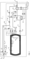
- Figure 1 depicts schematically a fuel tank arrangement in a liquid hydrogen fuel supply system 1 for storing and providing hydrogen for a gas consumer 8, the system comprising:
- the arrangement is utilized by a method in filling a liquid hydrogen fuel supply system 1 for storing and providing liquid hydrogen for a gas consumer 8, the method comprising steps of:
- the liquid hydrogen fuel supply system 1 is arranged so that the source of gaseous hydrogen 15 is a device for increasing pressure and temperature of gaseous hydrogen and it is connected to or supplied by gaseous or liquid hydrogen in the tank 10.
- the numeral 15 refers schematically in Fig 1 to an initial spot in the fuel gas flush line 14 where the actual devices outlet may be connected.
- the numeral 15 points to an intersection where both options, a main gas evaporator 151 or a pressure built-up evaporator 152 that evaporates an amount of hydrogen may be selectably connected.
- Evaporation and subsequent heating can be powered for example by a source of external heat, such as the gas consumer cooling system, as illustrated in Fig. 1 with references for the heating fluid heat in (H_in) and heat out (H_out). It is also possible to use electric heating for this purpose.
- An electric heater may be integrated into the evaporator providing heat there directly, or into the heating fluid circuit providing additional heating into the fluid before it enters the evaporator.
- the added electric heater solves a problem that sufficient heat may not be available in the heating fluid at the moment a bunkering operation is completed, and the fuel line should be flushed and inerted.
- the inlet line temperature is above condensing temperature (Tn) of the inert gas and it is filled with fuel gas, gaseous hydrogen.
- Tn condensing temperature
- the inlet line 11 is provided with a temperature sensor 116 or a number of temperature sensors along the inlet line 11 for determining the temperature of the inlet line 11.
- the fuel gas flush line 14 is equipped with a temperature sensor 116. With the temperature information it is possible to determine the status of the inlet line 11 if it is in safe condition and ready for the next process step being the inert gas flushing.
- the fuel gas flush media line 14 is closed and the flushing with the inert gas can be initiated.
- the inlet line 11 is supplied with an inert gas via an inert gas flush media line 13 controllably connected to the inlet line 11 downstream of the first valve 111, the supplied inert gas flushing the hydrogen away from the inlet line 11 into the tank 10.
- the inert gas flush replaces the fuel gas in the inlet line 11 by pushing it to the tank 10. Therefore, the pressure and flow rate of the inert gas need to be selected so that the flushing may happen.
- Fig 1 It is presented one embodiment of liquid hydrogen fuel supply system 1 for storing and providing hydrogen for a gas consumer 8.
- the system gas is provided from the insulated tank 10 via outlet line 12 to one of the evaporators, either to the pressure build-up evaporator 151 and back to the tank 10, or the main gas evaporator 152 and then further to the gas consumer 8 such as an engine, fuel cell, etc..
- the pressure build-up evaporator is used for evaporating liquefied gas and feeding it back to the tank in order to maintain a pressure in the tank that is sufficiently high for the system operation.
- the pressure build-up evaporator is in operation based on need for increasing the pressure in the tank.
- a first option is to use the pressure build-up evaporator.
- the outlet line 12 valve 121 from the tank 10 is opened, and valve 122 for the line leading to the main gas evaporator 152 is closed.
- Heating fluid is arranged to flow through the pressure build-up evaporator 151.
- Valves 123 and 127 are open enabling circulation through the pressure build-up evaporator 151, which evaporates the liquid hydrogen.
- Valves 128, 125 and 126 being closed, and valves 124 and 141 open, the evaporated gas flows to the fuel gas flush media line 14.
- valves 141 and 112 open, and valve 111 closed, the fuel flush gas flushes the inlet line 11 towards the tank.
- a second option is to use the main gas evaporator 152 with liquid hydrogen from the tank 10.
- valve 122 for the line leading to the main gas evaporator 152 is opened, while valve 123 enabling circulation through the pressure build-up evaporator 151 is closed. Heating fluid is now arranged to flow through the main gas evaporator 152.
- valve 81 leading to gas consumers 8 closed, and valves 125 and 124 open and 127 closed the fuel flush gas is generated to be led to line 11 the same way as in option 1.
- a third option is to use gaseous hydrogen, so called boil off gas from the tank 10.
- valves 126 and 128 By opening valves 126 and 128, closing valves 121, 123 and 127, gaseous hydrogen is led to the main gas evaporator 152 for pressure and temperature increase. With valve 81 leading to gas consumers 8 closed, and valves 125 and 124 open and 127 closed, the fuel flush gas is generated to be led to line 11 the same way as in option 1 and option 2.
- both the build-up evaporator 151 and main gas evaporator 152 could be used as parallel evaporators for generating the fuel flush gas.
- the fuel tank arrangement in Fig. 1 is provided with a tank connection space 100 for comparting connections to and from the tank 10.
- the fuel supply system is equipped with a number of control valves 121, 122, 123, 124, 125, 126, 127, 128, 81 shown with standard symbol for valves in Figures 1 and 2 .
- a person familiar with the art should understand which valve need to be closed and which valve need to be open or regulated to perform the function of the system.
- Fig. 2 it is presented a fuel tank arrangement in a liquid hydrogen fuel supply system 1 for storing and providing hydrogen for a gas consumer 8, the system comprising:
- the generation of the fuel flush gas can be made in a following way.
- Heating fluid is arranged to flow through the main gas evaporator 152, which evaporates and heats the liquid hydrogen.
- Valve 81 leading to gas consumers 8 being closed, and valves 124 and 141 open, the evaporated gas flows to the fuel gas flush media line 14. With valves 141 and 112 open, and valve 111 closed, the fuel flush gas flushes the inlet line 11 towards the tank 10.
Landscapes
- Engineering & Computer Science (AREA)
- Mechanical Engineering (AREA)
- Chemical & Material Sciences (AREA)
- Combustion & Propulsion (AREA)
- Ocean & Marine Engineering (AREA)
- General Engineering & Computer Science (AREA)
- Physics & Mathematics (AREA)
- Thermal Sciences (AREA)
- Filling Or Discharging Of Gas Storage Vessels (AREA)
Claims (15)
- Dispositif de réservoir de carburant dans un système d'alimentation en carburant à hydrogène liquide (1) pour stocker et fournir de l'hydrogène à un consommateur de gaz (8), le système comprenant :- une conduite d'admission (11) pour alimenter en carburant un réservoir (10)- la conduite d'admission (11) ayant une première vanne (111) à la première extrémité et une deuxième vanne (112) à l'extrémité du réservoir,- la conduite d'admission (11) est pourvue d'une conduite de fluide de rinçage au gaz inerte (13), dont la première extrémité est raccordée à la conduite d'admission (11) en aval de la première vanne (111) et dont une deuxième extrémité est raccordée de manière contrôlable à une source de gaz inerte (130) pour effectuer un rinçage au gaz inerte de la conduite d'admission (11), caractérisé en ce que le système comprend en outre- la conduite d'admission (11) étant pourvue d'une conduite de fluide de rinçage au gaz combustible (14), dont la première extrémité est raccordée de manière contrôlable à la conduite d'admission (11) en aval de la première vanne (111) et dont une deuxième extrémité est raccordée à une source d'hydrogène gazeux (15) pour alimenter en hydrogène gazeux la conduite d'admission (11) pour effectuer un premier rinçage de la conduite d'admission (11).
- Dispositif dans un système d'alimentation en carburant à hydrogène liquide (1) selon la revendication 1, caractérisé en ce que la source d'hydrogène gazeux (15) est un dispositif pour augmenter la pression et la température de l'hydrogène gazeux et elle est raccordée à ou alimentée par l'hydrogène gazeux ou liquide dans le réservoir (10).
- Dispositif dans un système d'alimentation en carburant à hydrogène liquide (1) selon la revendication 1 ou 2, caractérisé en ce que la source d'hydrogène gazeux (15) est un évaporateur à gaz principal (152).
- Dispositif dans un système d'alimentation en carburant à hydrogène liquide (1) selon la revendication 1 ou 2, caractérisé en ce que la source d'hydrogène gazeux (15) est un évaporateur à montée en pression (151).
- Dispositif dans un système d'alimentation en hydrogène liquide (1) selon une quelconque des revendications précédentes, caractérisé en ce que la conduite d'admission (11) est munie d'un capteur de température (116) pour déterminer la température de la conduite d'admission (11).
- Dispositif dans un système d'alimentation en hydrogène liquide (1) selon une quelconque des revendications précédentes, caractérisé en ce que le dispositif de réservoir de carburant est muni d'un espace de raccordement de réservoir (100) pour distribuer les raccordements vers et depuis le réservoir (10).
- Dispositif dans un système d'alimentation en hydrogène liquide (1) selon une quelconque des revendications précédentes, caractérisé en ce que le dispositif comprend un dispositif d'augmentation de pression, qui est une pompe, un accumulateur de pression ou similaire.
- Dispositif dans un système d'alimentation en hydrogène liquide (1) selon une quelconque des revendications précédentes, caractérisé en ce que le gaz inerte est de l'azote.
- Procédé de remplissage d'un système d'alimentation en hydrogène liquide (1) pour stocker et fournir de l'hydrogène liquide à un consommateur de gaz (8), le procédé comprenant les étapes suivantes :- alimenter un réservoir (10) par l'intermédiaire d'une conduite d'admission (11) à partir d'un raccordement de station de soutage (B), avec une quantité prédéterminée d'hydrogène liquide, la conduite d'admission (11) comportant une première vanne (111) à la première extrémité et une deuxième vanne (112) à l'extrémité du réservoir et après ladite alimentation, fermer la première vanne (111),- inerter la conduite d'admission (11) en alimentant un gaz inerte par l'intermédiaire d'une conduite de fluide de rinçage au gaz inerte (13) raccordée de manière contrôlable à la conduite d'admission (11) en aval de la première vanne (111), le gaz inerte fourni rinçant l'hydrogène de la conduite d'admission (11) vers le réservoir (10),caractérisé en ce que le procédé comprend en outre :- entre l'étape d'alimentation et l'étape d'inertage, une étape de rinçage au gaz combustible est effectuée, dans laquelle l'hydrogène gazeux est alimenté à partir d'une source d'hydrogène gazeux (15) vers la conduite d'admission (11) via une conduite de fluide de rinçage au gaz combustible (14) raccordée à la conduite d'admission (11) en aval de la première vanne (11), l'hydrogène gazeux rinçant la conduite d'admission (11) et réchauffant simultanément la conduite d'admission (11).
- Procédé dans un système d'alimentation en carburant à hydrogène liquide (1) selon la revendication 9 ou une quelconque des revendications précédentes, caractérisé en ce que pour le rinçage au gaz combustible, une quantité d'hydrogène liquide est évaporée en phase gazeuse et réchauffée à une température prédéterminée supérieure à Tn, dans lequel Tn est la température de condensation du gaz inerte.
- Procédé dans un système d'alimentation en carburant à hydrogène liquide (1) selon la revendication 9 ou une quelconque des revendications précédentes, caractérisé en ce que la température de la conduite d'admission (11) est surveillée et après que la température de la conduite d'admission (11) est déterminée comme étant supérieure à Tn, la conduite de fluide de rinçage au gaz combustible (14) est fermée et le rinçage au gaz inerte peut être amorcé.
- Procédé dans un système d'alimentation en carburant à hydrogène liquide (1) selon la revendication 9 ou une quelconque des revendications précédentes, caractérisé en ce que l'achèvement du rinçage au gaz inerte est déterminé en mesurant la concentration du gaz inerte dans l'extrémité de réservoir de la conduite d'admission (11).
- Procédé dans un système d'alimentation en carburant à hydrogène liquide (1) selon la revendication 9 ou une quelconque des revendications précédentes, caractérisé en ce que la source d'hydrogène gazeux (15) est le réservoir (10), un évaporateur de gaz principal (152) ou un évaporateur à pression accumulée (151) qui évapore une quantité d'hydrogène.
- Procédé dans un système d'alimentation en carburant à hydrogène liquide (1) selon la revendication 9 ou une quelconque des revendications précédentes, caractérisé en ce que le rinçage au gaz combustible pousse tout hydrogène liquide restant dans la conduite d'admission (11) vers le réservoir (10) et évapore les éventuels petits résidus d'hydrogène liquide.
- Procédé dans un système d'alimentation en carburant à hydrogène liquide (1) selon une quelconque des revendications précédentes, caractérisé en ce que le rinçage au gaz inerte remplace le gaz combustible dans la conduite d'admission (11) en le poussant vers le réservoir (10).
Applications Claiming Priority (1)
| Application Number | Priority Date | Filing Date | Title |
|---|---|---|---|
| PCT/EP2021/064970 WO2022253441A1 (fr) | 2021-06-04 | 2021-06-04 | Agencement et procédé dans un système d'alimentation en carburant hydrogène liquide |
Publications (2)
| Publication Number | Publication Date |
|---|---|
| EP4348096A1 EP4348096A1 (fr) | 2024-04-10 |
| EP4348096B1 true EP4348096B1 (fr) | 2025-04-02 |
Family
ID=76392348
Family Applications (1)
| Application Number | Title | Priority Date | Filing Date |
|---|---|---|---|
| EP21731720.5A Active EP4348096B1 (fr) | 2021-06-04 | 2021-06-04 | Agencement et procédé dans un système d'alimentation en carburant hydrogène liquide |
Country Status (5)
| Country | Link |
|---|---|
| EP (1) | EP4348096B1 (fr) |
| KR (1) | KR20240014069A (fr) |
| CN (1) | CN117529627A (fr) |
| FI (1) | FI4348096T3 (fr) |
| WO (1) | WO2022253441A1 (fr) |
Families Citing this family (1)
| Publication number | Priority date | Publication date | Assignee | Title |
|---|---|---|---|---|
| EP4667811A1 (fr) * | 2024-06-20 | 2025-12-24 | Cummins, Inc. | Systèmes et procédés de construction de pression lors de l'utilisation d'un stockage d'hydrogène liquide à basse pression |
Family Cites Families (9)
| Publication number | Priority date | Publication date | Assignee | Title |
|---|---|---|---|---|
| GB0313483D0 (en) * | 2003-06-11 | 2003-07-16 | Boc Group Plc | Liquefied gas storage installation |
| FI122608B (fi) * | 2007-11-12 | 2012-04-13 | Waertsilae Finland Oy | Menetelmä LNG-käyttöisen vesialuksen käyttämiseksi ja LNG-käyttöisen vesialuksen käyttöjärjestelmä |
| DE102012207821A1 (de) * | 2012-05-10 | 2013-11-14 | Bayerische Motoren Werke Aktiengesellschaft | Tankentlüftungssystem eines Kraftfahrzeugs |
| DE102013006301B4 (de) * | 2013-04-12 | 2023-09-21 | Man Energy Solutions Se | Kraftstoffzuführ- und Spüleinrichtung für einen Gasmotor |
| CN107023748A (zh) * | 2017-05-26 | 2017-08-08 | 江南造船(集团)有限责任公司 | 非lng预冷船舶燃气首次加注方法 |
| WO2019038364A2 (fr) * | 2017-08-23 | 2019-02-28 | Englemer B.V.B.A. | Procédé et système pour vidanger un tuyau de transfert de gaz liquide |
| CN107339610A (zh) * | 2017-08-25 | 2017-11-10 | 成都华气厚普机电设备股份有限公司 | 一种海船lng燃料高压供气系统及其控制方法 |
| CN107339611A (zh) * | 2017-08-25 | 2017-11-10 | 成都华气厚普机电设备股份有限公司 | 一种海船lng燃料低压供气系统及其控制方法 |
| CN113574308B (zh) | 2019-03-14 | 2023-04-07 | 瓦锡兰芬兰有限公司 | 海上船舶中的燃料箱装置和从液态氢燃料箱装置中释放氢气的方法 |
-
2021
- 2021-06-04 FI FIEP21731720.5T patent/FI4348096T3/fi active
- 2021-06-04 EP EP21731720.5A patent/EP4348096B1/fr active Active
- 2021-06-04 CN CN202180098792.9A patent/CN117529627A/zh active Pending
- 2021-06-04 KR KR1020237044771A patent/KR20240014069A/ko active Pending
- 2021-06-04 WO PCT/EP2021/064970 patent/WO2022253441A1/fr not_active Ceased
Also Published As
| Publication number | Publication date |
|---|---|
| KR20240014069A (ko) | 2024-01-31 |
| CN117529627A (zh) | 2024-02-06 |
| EP4348096A1 (fr) | 2024-04-10 |
| FI4348096T3 (fi) | 2025-07-10 |
| WO2022253441A1 (fr) | 2022-12-08 |
Similar Documents
| Publication | Publication Date | Title |
|---|---|---|
| US11920737B2 (en) | Device and method for storing and for supplying fluid fuel | |
| US6474101B1 (en) | Natural gas handling system | |
| US7810669B2 (en) | Replaceable cartridge for liquid hydrogen | |
| US9903535B2 (en) | Cryogenic liquid conditioning and delivery system | |
| CN105659021B (zh) | 用于将以液化形式储存的流体以气体形式递送至最终用户的系统和方法 | |
| CN203161377U (zh) | 一种船舶动力装置的气体燃料供给系统 | |
| US8191584B2 (en) | Method and device for filling pressure containers with low-boiling permanent gases or gas mixtures | |
| EP3084286B1 (fr) | Transfert de gaz naturel liquéfié | |
| JP6646907B2 (ja) | 船舶用の液化ガス燃料供給機構 | |
| US20230375136A1 (en) | Fuel delivery system | |
| US7165408B2 (en) | Method of operating a cryogenic liquid gas storage tank | |
| KR20210059711A (ko) | 가스 연료 선박용의 연료 탱크 장치 | |
| EP4348096B1 (fr) | Agencement et procédé dans un système d'alimentation en carburant hydrogène liquide | |
| Correa-Jullian et al. | Liquid hydrogen storage system FMEA and data requirements for risk analysis | |
| AU2018344229B2 (en) | Fuel cell system | |
| JP2007113442A (ja) | ボイルオフガスを利用した廃熱回収システム | |
| WO2023274559A1 (fr) | Agencement et procédé dans un système d'alimentation en carburant hydrogène liquide | |
| KR200431697Y1 (ko) | 질소산화물 배출억제 재기화 기능을 갖는 전기추진액화천연가스운반선 | |
| JP2009103165A (ja) | 低温液化ガス輸送車 | |
| KR102132151B1 (ko) | Lpg 선박 추진 시스템 | |
| RU2746579C1 (ru) | Установка для регазификации жидкости и подачи топлива в энергоустановку | |
| Lv et al. | The design and development of the cryogenic compressed gas refueling system | |
| KR20250129812A (ko) | 가스 연료를 저장하는 탱크 장치의 작동 방법 및 가스 연료를 저장하는 탱크 장치 | |
| Ahluwalia et al. | On‐Board Safety | |
| OBrien et al. | Investigation of low-cost LNG vehicle fuel tank concepts. Final report |
Legal Events
| Date | Code | Title | Description |
|---|---|---|---|
| STAA | Information on the status of an ep patent application or granted ep patent |
Free format text: STATUS: UNKNOWN |
|
| STAA | Information on the status of an ep patent application or granted ep patent |
Free format text: STATUS: THE INTERNATIONAL PUBLICATION HAS BEEN MADE |
|
| PUAI | Public reference made under article 153(3) epc to a published international application that has entered the european phase |
Free format text: ORIGINAL CODE: 0009012 |
|
| STAA | Information on the status of an ep patent application or granted ep patent |
Free format text: STATUS: REQUEST FOR EXAMINATION WAS MADE |
|
| 17P | Request for examination filed |
Effective date: 20240125 |
|
| AK | Designated contracting states |
Kind code of ref document: A1 Designated state(s): AL AT BE BG CH CY CZ DE DK EE ES FI FR GB GR HR HU IE IS IT LI LT LU LV MC MK MT NL NO PL PT RO RS SE SI SK SM TR |
|
| DAV | Request for validation of the european patent (deleted) | ||
| DAX | Request for extension of the european patent (deleted) | ||
| GRAP | Despatch of communication of intention to grant a patent |
Free format text: ORIGINAL CODE: EPIDOSNIGR1 |
|
| STAA | Information on the status of an ep patent application or granted ep patent |
Free format text: STATUS: GRANT OF PATENT IS INTENDED |
|
| INTG | Intention to grant announced |
Effective date: 20241022 |
|
| GRAS | Grant fee paid |
Free format text: ORIGINAL CODE: EPIDOSNIGR3 |
|
| GRAA | (expected) grant |
Free format text: ORIGINAL CODE: 0009210 |
|
| STAA | Information on the status of an ep patent application or granted ep patent |
Free format text: STATUS: THE PATENT HAS BEEN GRANTED |
|
| AK | Designated contracting states |
Kind code of ref document: B1 Designated state(s): AL AT BE BG CH CY CZ DE DK EE ES FI FR GB GR HR HU IE IS IT LI LT LU LV MC MK MT NL NO PL PT RO RS SE SI SK SM TR |
|
| REG | Reference to a national code |
Ref country code: GB Ref legal event code: FG4D |
|
| REG | Reference to a national code |
Ref country code: CH Ref legal event code: EP |
|
| REG | Reference to a national code |
Ref country code: DE Ref legal event code: R096 Ref document number: 602021028522 Country of ref document: DE |
|
| REG | Reference to a national code |
Ref country code: IE Ref legal event code: FG4D |
|
| REG | Reference to a national code |
Ref country code: NL Ref legal event code: FP |
|
| PGFP | Annual fee paid to national office [announced via postgrant information from national office to epo] |
Ref country code: FI Payment date: 20250627 Year of fee payment: 5 |
|
| PGFP | Annual fee paid to national office [announced via postgrant information from national office to epo] |
Ref country code: DE Payment date: 20250618 Year of fee payment: 5 |
|
| REG | Reference to a national code |
Ref country code: FI Ref legal event code: FGE |
|
| PGFP | Annual fee paid to national office [announced via postgrant information from national office to epo] |
Ref country code: NO Payment date: 20250624 Year of fee payment: 5 |
|
| PGFP | Annual fee paid to national office [announced via postgrant information from national office to epo] |
Ref country code: NL Payment date: 20250618 Year of fee payment: 5 |
|
| REG | Reference to a national code |
Ref country code: SE Ref legal event code: TRGR |
|
| PGFP | Annual fee paid to national office [announced via postgrant information from national office to epo] |
Ref country code: FR Payment date: 20250627 Year of fee payment: 5 |
|
| PGFP | Annual fee paid to national office [announced via postgrant information from national office to epo] |
Ref country code: AT Payment date: 20250721 Year of fee payment: 5 |
|
| PGFP | Annual fee paid to national office [announced via postgrant information from national office to epo] |
Ref country code: TR Payment date: 20250623 Year of fee payment: 5 |
|
| PGFP | Annual fee paid to national office [announced via postgrant information from national office to epo] |
Ref country code: SE Payment date: 20250618 Year of fee payment: 5 |
|
| REG | Reference to a national code |
Ref country code: AT Ref legal event code: MK05 Ref document number: 1781570 Country of ref document: AT Kind code of ref document: T Effective date: 20250402 |
|
| PG25 | Lapsed in a contracting state [announced via postgrant information from national office to epo] |
Ref country code: ES Free format text: LAPSE BECAUSE OF FAILURE TO SUBMIT A TRANSLATION OF THE DESCRIPTION OR TO PAY THE FEE WITHIN THE PRESCRIBED TIME-LIMIT Effective date: 20250402 Ref country code: PT Free format text: LAPSE BECAUSE OF FAILURE TO SUBMIT A TRANSLATION OF THE DESCRIPTION OR TO PAY THE FEE WITHIN THE PRESCRIBED TIME-LIMIT Effective date: 20250804 |
|
| REG | Reference to a national code |
Ref country code: LT Ref legal event code: MG9D |
|
| PG25 | Lapsed in a contracting state [announced via postgrant information from national office to epo] |
Ref country code: GR Free format text: LAPSE BECAUSE OF FAILURE TO SUBMIT A TRANSLATION OF THE DESCRIPTION OR TO PAY THE FEE WITHIN THE PRESCRIBED TIME-LIMIT Effective date: 20250703 |
|
| PG25 | Lapsed in a contracting state [announced via postgrant information from national office to epo] |
Ref country code: PL Free format text: LAPSE BECAUSE OF FAILURE TO SUBMIT A TRANSLATION OF THE DESCRIPTION OR TO PAY THE FEE WITHIN THE PRESCRIBED TIME-LIMIT Effective date: 20250402 |
|
| PGFP | Annual fee paid to national office [announced via postgrant information from national office to epo] |
Ref country code: IT Payment date: 20250730 Year of fee payment: 5 |
|
| PG25 | Lapsed in a contracting state [announced via postgrant information from national office to epo] |
Ref country code: BG Free format text: LAPSE BECAUSE OF FAILURE TO SUBMIT A TRANSLATION OF THE DESCRIPTION OR TO PAY THE FEE WITHIN THE PRESCRIBED TIME-LIMIT Effective date: 20250402 |
|
| PG25 | Lapsed in a contracting state [announced via postgrant information from national office to epo] |
Ref country code: HR Free format text: LAPSE BECAUSE OF FAILURE TO SUBMIT A TRANSLATION OF THE DESCRIPTION OR TO PAY THE FEE WITHIN THE PRESCRIBED TIME-LIMIT Effective date: 20250402 |
|
| PG25 | Lapsed in a contracting state [announced via postgrant information from national office to epo] |
Ref country code: AT Free format text: LAPSE BECAUSE OF FAILURE TO SUBMIT A TRANSLATION OF THE DESCRIPTION OR TO PAY THE FEE WITHIN THE PRESCRIBED TIME-LIMIT Effective date: 20250402 |
|
| PG25 | Lapsed in a contracting state [announced via postgrant information from national office to epo] |
Ref country code: RS Free format text: LAPSE BECAUSE OF FAILURE TO SUBMIT A TRANSLATION OF THE DESCRIPTION OR TO PAY THE FEE WITHIN THE PRESCRIBED TIME-LIMIT Effective date: 20250702 |
|
| PG25 | Lapsed in a contracting state [announced via postgrant information from national office to epo] |
Ref country code: IS Free format text: LAPSE BECAUSE OF FAILURE TO SUBMIT A TRANSLATION OF THE DESCRIPTION OR TO PAY THE FEE WITHIN THE PRESCRIBED TIME-LIMIT Effective date: 20250802 |
|
| PG25 | Lapsed in a contracting state [announced via postgrant information from national office to epo] |
Ref country code: LV Free format text: LAPSE BECAUSE OF FAILURE TO SUBMIT A TRANSLATION OF THE DESCRIPTION OR TO PAY THE FEE WITHIN THE PRESCRIBED TIME-LIMIT Effective date: 20250402 |
|
| REG | Reference to a national code |
Ref country code: DE Ref legal event code: R097 Ref document number: 602021028522 Country of ref document: DE |
|
| PG25 | Lapsed in a contracting state [announced via postgrant information from national office to epo] |
Ref country code: SM Free format text: LAPSE BECAUSE OF FAILURE TO SUBMIT A TRANSLATION OF THE DESCRIPTION OR TO PAY THE FEE WITHIN THE PRESCRIBED TIME-LIMIT Effective date: 20250402 Ref country code: DK Free format text: LAPSE BECAUSE OF FAILURE TO SUBMIT A TRANSLATION OF THE DESCRIPTION OR TO PAY THE FEE WITHIN THE PRESCRIBED TIME-LIMIT Effective date: 20250402 |
|
| PG25 | Lapsed in a contracting state [announced via postgrant information from national office to epo] |
Ref country code: CZ Free format text: LAPSE BECAUSE OF FAILURE TO SUBMIT A TRANSLATION OF THE DESCRIPTION OR TO PAY THE FEE WITHIN THE PRESCRIBED TIME-LIMIT Effective date: 20250402 |
|
| PG25 | Lapsed in a contracting state [announced via postgrant information from national office to epo] |
Ref country code: EE Free format text: LAPSE BECAUSE OF FAILURE TO SUBMIT A TRANSLATION OF THE DESCRIPTION OR TO PAY THE FEE WITHIN THE PRESCRIBED TIME-LIMIT Effective date: 20250402 |
|
| PG25 | Lapsed in a contracting state [announced via postgrant information from national office to epo] |
Ref country code: SK Free format text: LAPSE BECAUSE OF FAILURE TO SUBMIT A TRANSLATION OF THE DESCRIPTION OR TO PAY THE FEE WITHIN THE PRESCRIBED TIME-LIMIT Effective date: 20250402 |
|
| REG | Reference to a national code |
Ref country code: CH Ref legal event code: H13 Free format text: ST27 STATUS EVENT CODE: U-0-0-H10-H13 (AS PROVIDED BY THE NATIONAL OFFICE) Effective date: 20260127 |
|
| PG25 | Lapsed in a contracting state [announced via postgrant information from national office to epo] |
Ref country code: MC Free format text: LAPSE BECAUSE OF FAILURE TO SUBMIT A TRANSLATION OF THE DESCRIPTION OR TO PAY THE FEE WITHIN THE PRESCRIBED TIME-LIMIT Effective date: 20250402 |
|
| PLBE | No opposition filed within time limit |
Free format text: ORIGINAL CODE: 0009261 |
|
| STAA | Information on the status of an ep patent application or granted ep patent |
Free format text: STATUS: NO OPPOSITION FILED WITHIN TIME LIMIT |
|
| REG | Reference to a national code |
Ref country code: CH Ref legal event code: L10 Free format text: ST27 STATUS EVENT CODE: U-0-0-L10-L00 (AS PROVIDED BY THE NATIONAL OFFICE) Effective date: 20260211 |
|
| PG25 | Lapsed in a contracting state [announced via postgrant information from national office to epo] |
Ref country code: LU Free format text: LAPSE BECAUSE OF NON-PAYMENT OF DUE FEES Effective date: 20250604 |
|
| REG | Reference to a national code |
Ref country code: BE Ref legal event code: MM Effective date: 20250630 |
|
| PG25 | Lapsed in a contracting state [announced via postgrant information from national office to epo] |
Ref country code: RO Free format text: LAPSE BECAUSE OF FAILURE TO SUBMIT A TRANSLATION OF THE DESCRIPTION OR TO PAY THE FEE WITHIN THE PRESCRIBED TIME-LIMIT Effective date: 20250402 |
|
| 26N | No opposition filed |
Effective date: 20260105 |
|
| GBPC | Gb: european patent ceased through non-payment of renewal fee |
Effective date: 20250702 |
|
| PG25 | Lapsed in a contracting state [announced via postgrant information from national office to epo] |
Ref country code: GB Free format text: LAPSE BECAUSE OF NON-PAYMENT OF DUE FEES Effective date: 20250702 |
|
| PG25 | Lapsed in a contracting state [announced via postgrant information from national office to epo] |
Ref country code: IE Free format text: LAPSE BECAUSE OF NON-PAYMENT OF DUE FEES Effective date: 20250604 |
|
| PG25 | Lapsed in a contracting state [announced via postgrant information from national office to epo] |
Ref country code: BE Free format text: LAPSE BECAUSE OF NON-PAYMENT OF DUE FEES Effective date: 20250630 |
|
| PG25 | Lapsed in a contracting state [announced via postgrant information from national office to epo] |
Ref country code: CH Free format text: LAPSE BECAUSE OF NON-PAYMENT OF DUE FEES Effective date: 20250630 |