EP4349183A1 - Kürbiserntemaschine - Google Patents
Kürbiserntemaschine Download PDFInfo
- Publication number
- EP4349183A1 EP4349183A1 EP23201159.3A EP23201159A EP4349183A1 EP 4349183 A1 EP4349183 A1 EP 4349183A1 EP 23201159 A EP23201159 A EP 23201159A EP 4349183 A1 EP4349183 A1 EP 4349183A1
- Authority
- EP
- European Patent Office
- Prior art keywords
- thresher
- threshers
- harvesting machine
- machine according
- crusher
- Prior art date
- Legal status (The legal status is an assumption and is not a legal conclusion. Google has not performed a legal analysis and makes no representation as to the accuracy of the status listed.)
- Granted
Links
Images


Classifications
-
- A—HUMAN NECESSITIES
- A01—AGRICULTURE; FORESTRY; ANIMAL HUSBANDRY; HUNTING; TRAPPING; FISHING
- A01D—HARVESTING; MOWING
- A01D45/00—Harvesting of standing crops
-
- A—HUMAN NECESSITIES
- A01—AGRICULTURE; FORESTRY; ANIMAL HUSBANDRY; HUNTING; TRAPPING; FISHING
- A01F—PROCESSING OF HARVESTED PRODUCE; HAY OR STRAW PRESSES; DEVICES FOR STORING AGRICULTURAL OR HORTICULTURAL PRODUCE
- A01F11/00—Threshing apparatus specially adapted for maize; Threshing apparatus specially adapted for particular crops other than cereals
-
- A—HUMAN NECESSITIES
- A01—AGRICULTURE; FORESTRY; ANIMAL HUSBANDRY; HUNTING; TRAPPING; FISHING
- A01D—HARVESTING; MOWING
- A01D41/00—Combines, i.e. harvesters or mowers combined with threshing devices
- A01D41/04—Tractor-driven combines
-
- A—HUMAN NECESSITIES
- A01—AGRICULTURE; FORESTRY; ANIMAL HUSBANDRY; HUNTING; TRAPPING; FISHING
- A01D—HARVESTING; MOWING
- A01D51/00—Apparatus for gathering together crops spread on the soil, e.g. apples, beets, nuts, potatoes, cotton, cane sugar
-
- A—HUMAN NECESSITIES
- A01—AGRICULTURE; FORESTRY; ANIMAL HUSBANDRY; HUNTING; TRAPPING; FISHING
- A01D—HARVESTING; MOWING
- A01D91/00—Methods for harvesting agricultural products
-
- A—HUMAN NECESSITIES
- A23—FOODS OR FOODSTUFFS; TREATMENT THEREOF, NOT COVERED BY OTHER CLASSES
- A23N—MACHINES OR APPARATUS FOR TREATING HARVESTED FRUIT, VEGETABLES OR FLOWER BULBS IN BULK, NOT OTHERWISE PROVIDED FOR; PEELING VEGETABLES OR FRUIT IN BULK; APPARATUS FOR PREPARING ANIMAL FEEDING- STUFFS
- A23N4/00—Machines for stoning fruit or removing seed-containing sections from fruit, characterised by their stoning or removing device
- A23N4/12—Machines for stoning fruit or removing seed-containing sections from fruit, characterised by their stoning or removing device for coring fruit
-
- A—HUMAN NECESSITIES
- A23—FOODS OR FOODSTUFFS; TREATMENT THEREOF, NOT COVERED BY OTHER CLASSES
- A23N—MACHINES OR APPARATUS FOR TREATING HARVESTED FRUIT, VEGETABLES OR FLOWER BULBS IN BULK, NOT OTHERWISE PROVIDED FOR; PEELING VEGETABLES OR FRUIT IN BULK; APPARATUS FOR PREPARING ANIMAL FEEDING- STUFFS
- A23N4/00—Machines for stoning fruit or removing seed-containing sections from fruit, characterised by their stoning or removing device
- A23N4/24—Machines for stoning fruit or removing seed-containing sections from fruit, characterised by their stoning or removing device for removing seed-containing sections from cut fruit
Definitions
- the invention relates to a pumpkin harvesting machine which collects the harvested crop using a spiked roller, further chops it up in a crusher and then separates it into fruit parts and seeds in a thresher, throws out the fruit parts and cleans the seeds as needed and finally feeds them into a grain tank.
- the large-scale cultivation of pumpkins serves to extract oil from their seeds.
- a pumpkin harvesting machine is known that is constructed in the manner of a self-propelled combine harvester.
- a boom with intake rotors picks up the pumpkins. Further shredding and separation takes place in a lengthwise direction. It is a large and bulky self-propelled special machine, which is uneconomical for that reason alone.
- a pumpkin harvesting machine that picks up the pumpkins using a spiked roller that determines the working width. From there, the pumpkins are fed via a conveyor belt to a crusher and then by several conveyor screws to a threshing drum and via further conveyors to a cleaning drum.
- the many conveyors limit the throughput capacity and make the machine bulky. In addition, the hard parts of the pumpkin shells seriously hinder the separation of the pulp.
- the invention is therefore based on the object of arranging the individual processing stations in such a way that, with a high throughput, a perfect separation of the cores is achieved with a minimum of conveyor devices and installation space as well as drive power requirements.
- the entire machine should be able to be attached as an attachment to the lifting gear of a tractor. According to the invention, this is achieved with an arrangement according to the features of claim 1.
- the transition from the spiked roller to the crusher and from there to the first thresher and then to the second threshers is carried out directly by gravity, without any separate conveying means.
- the first thresher which conveys symmetrically in both directions, and the parallel doubling of the second threshers increases the throughput capacity and thus the possible driving speed.
- the longitudinal arrangement of the second threshers allows the width permitted for road vehicles to be maintained at the maximum working width. This arrangement also facilitates the purely mechanical drive of the rotors and the few conveying devices from the tractor's power take-off shaft. Overall, this results in a low construction volume and weight for the entire machine, making it suitable for attachment to a tractor.
- the secondary threshers ensure that all of the pulp is ejected until the seeds have been cleaned. Thanks to the casing, the ejection takes place outwards along the entire length of the secondary thresher.
- the following training courses also contribute to solving the task:
- the pumpkins roll by gravity over the stripping plate, which is inclined towards the crusher, on the shortest route to the crusher where they are crushed.
- the pumpkin is further chopped in the first thresher.
- the crop flow is divided, chopped and guided to both ends.
- the seeds are separated on the sieve bars.
- the sieve bars form a threshing concave as part of the first drum. They are spaced far enough apart that they are not blocked by parts of the pumpkin shells. Thanks to the transversely and lengthwise aligned bars, the harvested crop (pulp, shell parts and seeds) also falls onto the conveyor screw arranged underneath, which also works in both directions.
- the sieve bars replace the usual holes, which easily become blocked.
- the throughput capacity is increased and the shell parts emerge from both through their open ends so that they can no longer hinder further separation.
- the blades of the first and second rotors which do not touch the inside of the threshing drums, throw the material that has been freed from the husks through the longitudinally aligned bars. They could also be aligned transversely.
- the Archimedean spirals at the end of the second rotors convey the husk parts to the ejection point.
- the radially aligned bars between the blades are welded to the rotors. They slow down the passage of the material through the threshing drums so that the material is processed more intensively.
- Arranging the secondary threshers above the second threshers saves space and reduces the width of the entire machine.
- the conveyor augers are positioned so that they can be easily driven from the input of the PTO shaft.
- the perforated sheet surrounding the secondary thresher forms the third drum and holds back the kernels.
- the blades resting on the perforated sheet press the pulp completely through the perforated sheet, so that only the pure kernels remain inside the perforated sheet.
- the cladding only on the inside and underside of the rotors allows the pulp to be ejected outwards and thus evenly distributed over the field.
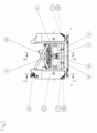
- Fig. 1 - 4 are views from the outside, which initially describe the flow of the harvested goods (pumpkins) in rough outline.
- the pivot points 9 of the tractor's lifting gear and a power take-off shaft 10 of the machine are indicated on the back of the machine.
- a spiked roller 1 is mounted on a rotating basis at the front, which impales the pumpkins and takes them upwards to a crusher 2, for which it does not require its own drive.
- the spiked roller is arranged transversely and centrally and takes up a large part of the width of the entire machine.
- a crusher 2 in which the pumpkins are chopped between spirally arranged knives.
- a first thresher 4 which further chops up the chopped crop and conveys it outwards from its longitudinal center in both directions.
- the second threshers 5 which are arranged lengthwise on both sides, in which it is further chopped up and the pumpkin shells are ejected at the ends.
- the chopped crop is also fed to the first conveyor devices 6 by first conveyor screws 22 arranged underneath.
- the first conveyor devices 6 on both sides lift the harvested crop to the double-sided threshers 7 arranged above the second threshers 5.
- the fruit pulp is ejected to the side and the kernels are collected at one end.
- two threshers 7, 7* are arranged one above the other, with the transition from the first to the second thresher also only being caused by gravity. In this way, even the last remnants of the fruit pulp are separated from the kernels in the lower thresher 7.
- the kernels emerge at the other end 12, 42 of the lower of the two threshers 7. If there is only a single thresher 7 on both sides, the other end 12, 42 is on the side opposite the second conveyor device 6.
- the kernels emerging at the end 12, 42 of the thresher 7 are picked up by third conveyor devices 45 and conveyed to a kernel tank (not shown). This can be installed at any location; so also at the other end of the tractor.
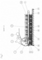
- the crusher 2 consists of a knife roller 15 and a housing 16, which carries counter knives 50 and merges into a stripping plate 14. This protrudes between the spikes 49 of the spiked roller 1, which in Fig.5 rotates anti-clockwise. Pumpkins are 48 is indicated. A back wall 51 prevents them from falling prematurely and ensures that all pumpkins are accommodated.
- the first thresher 4 consists of a stationary first drum 17 arranged transversely to the direction of travel 3 and a first rotor 18 therein. At least the lower part of the drum 17 is formed from longitudinally directed rods 19, under which there is a first conveyor screw 22 which also acts in opposite directions.
- the first rotor 18 has oppositely inclined paddle blades 20 on both sides, which convey the crop from the center to the outer ends 21 and which do not touch the interior of the first drum 17.
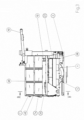
- the second threshers 5 each consist of a stationary second drum 23 and a second rotor 24.
- the drums 23 have longitudinally directed rods 25 at least on their lower part. They could also be curved and arranged transversely. Below this there is a first conveyor screw. At the end remote from the entrance 22, the drums 23 are open.
- the second rotors 24 of the second threshers 5 carry inclined blades 20 which do not touch the inside of the threshing drum 17 and carry a spiral 30 on the side of the exit openings 28 which move the pumpkin shells to these exit openings 28 and eject them.
- the second rotors 24 of the second threshers 5 have radially directed rods 31 between the inclined blades 20. These have the purpose of reducing the residence time of the harvested material in the drums 23 (and also 17). and thus improve the separation of the crop. The same applies to the first rotors 18 and the second rotors 24.
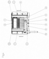
- each of the second threshers 5 there is also a trough 33 into which the harvested material (pulp and kernels) is thrown.
- the troughs 33 each contain a second conveyor screw 37 or a pair of conveyor screws 37, which feed the harvested material to the first conveyor devices 6.
- the conveyor devices 6 on both sides contain a substantially vertical third conveyor screw 38, which feeds the material to the secondary threshers 7.
- the two-sided secondary threshers 7 each consist of a stationary threshing drum 35 and a third rotor 34, with the threshing drums 35 being designed as perforated plates 40 surrounding the rotors 34.
- the rotors 34 carry inclined shovel blades 20 which touch the perforated plate 40, with the crop entering at one side 41 and the kernels exiting at the other end 12, 42.
- the fruit pulp is pressed through the perforated plates 19 by the shovel blades 29 touching the perforated plate and ejected.
- a cover 39 is attached to hurl the fruit pulp outwards.
- a further thresher 7* is arranged in series above each of the threshers 7.
- the kernels emerge from the thresher 7 on the side where the crop enters the further thresher 7*.
- the kernels emerging at the other end 12, 42 of the thresher 7 are picked up by third conveyor devices 45 and conveyed to a grain tank (not shown).
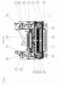
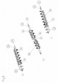
- Fig.8 b) shows the first rotor 18 of the first thresher 4 and a) and c) show the second rotors 24 of the second threshers 5 on both sides.
- the first rotor 18 is a first shaft 53 with a central radial separating disk or separating spiral 54 and on both sides blades 20, preferably made of a suitable flexible plastic, which each convey outwards, the blades 20 on the right in the picture to the right and the left 20 to the left.
- Radial rods 31 are mounted between the blades 20, one being offset from the next by a right angle.
- the second rotors 24 have on a second shaft 56 blades 26 similar to the blades 20 and in the conveying direction a spiral 30 each adjoining them, which eject the shell parts of the pumpkins.
Landscapes
- Life Sciences & Earth Sciences (AREA)
- Environmental Sciences (AREA)
- Chemical & Material Sciences (AREA)
- Engineering & Computer Science (AREA)
- Food Science & Technology (AREA)
- Polymers & Plastics (AREA)
- Threshing Machine Elements (AREA)
Abstract
Description
- Die Erfindung betrifft eine Kürbiserntemaschine, die das Erntegut mittels einer Stachelwalze aufnimmt, es weiter in einem Brecher zerkleinert und in der Folge in einem Drescher in Fruchtteile und Samenkörner trennt, die Fruchtteile auswirft und die Samenkörner fallweise reinigt und schließlich einem Korntank zuführt. Der großflächige Anbau von Kürbissen dient der Gewinnung eines Öles aus deren Kernen.
- Aus der
AT 403 754 B - In der
AT 15 522 U1 - Der Erfindung liegt daher die Aufgabe zugrunde, die einzelnen Bearbeitungsstellen so anzuordnen, dass bei hoher Durchlaufmenge mit einem Minimum an Fördervorrichtungen und Bauraum sowie Antriebsleistungsbedarf eine einwandfreie Trennung der Kerne gelingt. Die ganze Maschine soll als Anbaugerät am Hubwerk eines Traktors anbringbar sein. Erfindungsgemäß wird das mit einer Anordnung gemäß Merkmalen des Anspruchs 1 erreicht.
- Der Übergang von der Stachelwalze zum Brecher und von diesem zum ersten Drescher und weiter zu den zweiten Dreschern erfolgt direkt durch die Schwerkraft, ohne eigene Fördermittel. Der symmetrisch in beide Richtungen fördernde erste Drescher und die parallele Verdoppelung der zweiten Drescher erhöht die Durchlaufkapazität und damit die mögliche Fahrgeschwindigkeit. Die Anordnung der zweiten Drescher in Längsrichtung erlaubt bei maximaler Arbeitsbreite die Einhaltung der für Straßenfahrzeuge erlaubten Breite. Weiters erleichtert diese Anordnung den rein mechanischen Antrieb der Rotoren und der wenigen Fördervorrichtungen von der Zapfwelle des Traktors. Insgesamt wird so ein geringes Bauvolumen und Gewicht der ganzen Maschine erreicht, sodass sie für den Anbau an einen Traktor geeignet ist.
- Die Nachdrescher besorgen den restlosen Auswurf des Fruchtfleisches bis zur Reinigung der Kerne, wobei der Auswurf dank der Verkleidung über die ganze Länge des Nachdreschers nach außen erfolgt.
- Die folgenden Weiterbildungen tragen zusätzlich zur Lösung der gestellten Aufgabe bei:
Über das zum Brecher hin geneigte Abstreifblech rollen die Kürbisse durch Schwerkraft auf kürzestem Weg zum Brecher, in dem sie zerkleinert werden. - Im ersten Drescher wird der Kürbis weiter zerkleinert. Der Gutstrom wird geteilt, zerkleinert und zu den beidseitigen Enden geführt. Dabei werden an den Siebstäben Kerne abgeschieden. Die Siebstäbe bilden als Teil der ersten Trommel einen Dreschkorb. Ihr Abstand ist so groß, dass sie nicht von Teilen der Schalen der Kürbisse verstopft werden. Dank der quer längs gerichteten Stäbe fällt das Erntegut (Fruchtfleisch, Schalenteile und Kerne) auch auf die darunter angeordnete ebenfalls in beide Richtungen wirkende Förderschnecke. Die Siebstäbe ersetzen die üblichen Löcher, die leicht verstopfen.
- Durch die Verdoppelung der zweiten Drescher wird die Durchlaufkapazität gesteigert und durch deren offene Enden treten die Schalenteile aus beiden aus, sodass sie die weitere Trennung nicht mehr behindern können.
- Die das Innere der Dreschtrommeln nicht berührenden Schaufelblätter der ersten und zweiten Rotoren schleudern das von den Schalen befreite Gut durch die längs gerichteten Stäbe. Sie könnten auch quer gerichtet sein. Die archimedisch wirkenden Spiralen am Ende der zweiten Rotoren fördern die Schalenteile zum Auswurf.
- Die radial ausgerichteten Stäbe zwischen den Schaufelblättern sind an die Rotorhen angeschweißt. Sie verzögern den Durchlauf des Gutes durch die Dreschtrommeln, sodass das Gut intensiver bearbeitet wird.
- Die Anordnung der Nachdrescher über den zweiten Dreschern spart Bauraum und reduziert die Breite der ganzen Maschine. Die Förderschnecken liegen so, dass sie einfach vom Eingang der Zapfwelle aus antreibbar sind.
- Das die Nachdrescher umgebende Lochblech bildet die dritte Trommel und hält die Kerne zurück. Die hier am Lochblech anliegenden Schaufelblätter drücken das Fruchtfleisch restlos durch das Lochblech, sodass nur mehr die reinen Kerne innerhalb des Lochblechs verbleiben. Die Verkleidung nur an der Innenseite und der Unterseite der Rotoren erlaubt den Auswurf des Fruchtfleisches nach außen und so dessen gleichmäßige Verteilung über die Ackerfläche.
- Im Folgenden wird die Erfindung anhand einer bevorzugten Ausführungsform beschrieben und erläutert. Es stellen dar:
-
Fig. 1 Die ganze Kürbiserntemaschine, axonometrisch -
Fig. 2 Deren Vorderansicht, -
Fig. 3 Deren Seitenansicht, -
Fig. 4 Deren Draufsicht, -
Fig. 5 : Einen Querschnitt nach BB inFig. 3 , -
Fig. 6 : Einen Längsschnitt nach AA inFig.2 , -
Fig. 7 : Schnitt nach CC inFig. 5 , -
Fig. 8 : Die Rotoren der Drescher. - Die
Fig. 1 - 4 sind Ansichten von außen, anhand derer der Fluss des Erntegutes (Kürbisse) zunächst in groben Zügen beschrieben ist. An der Rückseite der Maschine sind die Anlenkpunkte 9 des Hubwerkes eines Traktors und ist ein Zapfwellenstummel 10 der Maschine angedeutet. Im Erntebetrieb, bei Fahrtrichtung 3, ist vorne eine Stachelwalze 1 drehbar gelagert, die die Kürbisse aufspießt und aufwärts bis zu einem Brecher 2 mitnimmt, wozu sie keinen eigenen Antrieb benötigt. Die Stachelwalze ist quer und mittig angeordnet und nimmt einen Großteil der Breite der ganzen Maschine ein. - An die Stachelwalze 1 schließt direkt und etwas tiefer ein Brecher 2 an, in dem die Kürbisse zwischen spiralförmig angestellten Messern zerhackt werden. Unter dem Brecher 2, ist (siehe auch
Fig. 5 ) ein erster Drescher 4, der das zerhackte Erntegut weiter zerkleinert und von seiner Längsmitte aus in beide Richtungen nach außen fördert. Dort gelangt es in die beidseitigen längs gerichteten zweiten Drescher 5, in denen es weiter zerkleinert wird und die Schalen der Kürbisse an den Enden ausgeworfen werden. Das zerkleinerte Gut wird auch von darunter angeordneten ersten Förderschnecken 22 ersten Fördervorrichtungen 6 zugeführt. - Die beidseitigen ersten Fördervorrichtungen 6 heben das Erntegut zu über den zweiten Dreschern 5 angeordneten beidseitigen Nachdreschern 7. In diesen wird das Fruchtfleisch nach der Seite ausgeworfen und die Kerne an einem Ende gesammelt. In der abgebildeten Ausführungsform sind jeweils zwei Nachdrescher 7, 7* übereinander angeordnet, wobei der Übergang vom ersten zum zweiten Nachdrescher auch nur durch die Schwerkraft bewirkt wird. So sind im unteren Nachdrescher 7 auch die letzten Reste des Fruchtfleisches von den Kernen getrennt. Die Kerne treten am anderen Ende 12, 42 des unteren der beiden Nachdrescher 7 aus. Wenn beiderseits nur ein einziger Nachdrescher 7 ist, befindet sich das andere Ende 12, 42 auf der der zweiten Fördervorrichtung 6 entgegengesetzten Seite. Die am Ende 12, 42 des Nachdreschers 7 austretenden Kerne werden von dritten Fördervorrichtungen 45 aufgenommen und zu einem nicht dargestellten Kerntank gefördert. Dieser kann an beliebiger Stelle angebracht sein; so auch am anderen Ende des Traktors.
- In
Fig. 5 ist der Brecher 2 und der unmittelbar darunter angeordnete erste Drescher 4 zu sehen. Der Brecher 2 besteht aus einer Messerwalze 15 und einem Gehäuse 16, das Gegenmesser 50 trägt und in ein Abstreifblech 14 übergeht. Dieses ragt zwischen die Stacheln 49 der Stachelwalze 1, welche inFig. 5 gegen den Uhrzeigersinn rotiert. Kürbisse sind 48 ist angedeutet. Eine Rückwand 51 verhindert deren vorzeitigen Absturz und stellt die Aufnahme aller Kürbisse sicher. - Der erste Drescher 4 besteht aus einer quer zur Fahrtrichtung 3 angeordneten stationären ersten Trommel 17 und darin einem ersten Rotor 18. Zumindest der untere Teil der Trommel 17 ist aus längs gerichteten Stäben 19 gebildet, unter denen eine ebenfalls in entgegengesetzte Richtungen wirkende erste Förderschnecke 22 ist. Der erste Rotor 18 hat beiderseits entgegengesetzt gerichtet schräg angestellte Schaufelblätter 20, die das Erntegut von der Mitte zu den äußeren Enden 21 fördern und die das Innere der ersten Trommel 17 nicht berühren.
- Unter den beiden äußeren Enden 21 (siehe
Fig. 6 und7 ) der ersten Drescher 4 ist der Eingang 27 in zweite Drescher 5, welche beiderseits in Längsrichtung angeordnet sind. Die zweiten Drescher 5 bestehen jeweils aus einer stationären zweiten Trommel 23 und einem zweiten Rotor 24. Die Trommeln 23 haben zumindest an ihrem unteren Teil längs gerichtete Stäbe 25. Sie könnten auch gebogen und quer angeordnet sein. Darunter befindet sich eine erste Förderschnecke. Am dem Eingang 22 abgelegenen Ende sind die Trommeln 23 offen. - Die zweiten Rotoren 24 der zweiten Drescher 5 tragen schräg angestellte Schaufelblätter 20, die das Innere der Dreschtrommel 17 nicht berühren und an der Seite der Ausgangsöffnungen 28 eine Spirale 30 tragen, die die Schalen der Kürbisse zu diesen Ausgangsöffnungen 28 bewegen und sie auswerfen. Die zweiten Rotoren 24 der zweiten Drescher 5 haben zwischen den schräg gestellten Schaufelblättern 20 radial gerichtete Stäbe 31. Diese haben den Zweck, die Verweilzeit des Erntegutes in den Trommeln 23 (und auch 17) zu verlängern und so die Trennung des Erntegutes zu verbessern. Ebenso die ersten Rotoren 18 und die zweiten Rotoren 24.
- Unter den zweiten Dreschern 5 ist jeweils auch eine Rinne 33, in die das Erntegut (Fruchtfleisch und Kerne) geschleudert wird. Die Rinnen 33 enthalten jeweils eine zweite Förderschnecke 37, beziehungsweise ein Paar von Förderschnecken 37, die das Erntegut weiter ersten Fördervorrichtungen 6 zuführen. Die Fördervorrichtungen 6 auf beiden Seiten enthalten eine im Wesentlichen vertikale dritte Förderschnecke 38, die das Gut den Nachdreschern 7 zuführt.
- Die beiderseitigen Nachdrescher 7 bestehen jeweils aus einer stationären Dreschtrommel 35 und einem dritten Rotor 34, wobei die Dreschtrommeln 35 als die Rotoren 34 umschließende Lochbleche 40 ausgebildet sind. Die Rotoren 34 tragen angestellte Schaufelblätter 20, die das Lochblech 40 berühren, wobei das Erntegut an einer Seite 41 eintritt und am anderen Ende 12, 42 die Kerne austreten. Das Fruchtfleisch wird von den das Lochblech berührenden Schaufelblättern 29 durch die Lochbleche 19 gedrückt und ausgeworfen. Um das Fruchtfleisch nach außen zu schleudern ist eine Verkleidung 39 angebracht.
- In der vorliegenden Ausführungsform ist über den Nachdreschern 7 jeweils ein weiterer Nachdrescher 7* in Serie angeordnet. Die Kerne treten aus dem Nachdrescher 7 auf der Seite des Eintrittes des Erntegutes in den weiteren Nachdrescher 7* aus. Die am anderen Ende 12, 42 des Nachdreschers 7 austretenden Kerne werden von dritten Fördervorrichtungen 45 aufgenommen und zu einem nicht gezeigten Korntank gefördert.
- In
Fig. 8 ist unter b) der erste Rotor 18 des ersten Dreschers 4 und sind unter a) und c) die zweiten Rotoren 24 der beidseitigen zweiten Drescher 5 zu sehen. Der erste Rotor 18 ist eine 1. Welle 53 mit einer mittigen radialen Trennscheibe oder Trennspirale 54 und beiderseits Schaufelblättern 20, vorzugsweise aus einem geeigneten nachgiebigen Kunststoff, welche jeweils nach außen fördern, die im Bild rechten Schaufelblätter 20 nach rechts und die linken 20 nach links. - Zwischen den Schaufelblättern 20 sind radiale Stäbe 31 angebracht, wobei einer gegen den Folgenden um einen rechten Winkel versetzt ist.
- Die zweiten Rotoren 24 haben auf einer zweiten Welle 56 den Schaufelblättern 20 gleichende Schaufelblätter 26 und in Förderrichtung daran anschließend je eine Spirale 30, die die Schalenteile der Kürbisse auswerfen.
- Insgesamt wird so eine Kürbiserntemaschine zur Verfügung gestellt, die bei geringen Ausmaßen, relativ geringem Gewicht und relativ geringem Leistungsbedarf eine hohe Erntegeschwindigkeit erreicht.
Claims (11)
- Kürbiserntemaschine, mit einer Stachelwalze (1) zum Aufnehmen von Erntegut, einem Brecher (2) zum zerkleinern des Ernteguts, mindestens einem Drescher zum anschließenden Trennen des Ernteguts in Fruchtteile und Samenkörnerund zum Zuführen der Samenkörner zu einem Korntank, dadurch gekennzeichnet, dassa) der Brecher (2) eine von einem Gehäuse (16) umgebene Messerwalze (15) mit zur Achse der Stachelwalze (1) paralleler Achse enthält, von welchem Gehäuse (16) ein Abstreifblech (14) direkt zwischen die Stacheln der Stachelwalze (1) reicht,b) ein erster Drescher (4), der unmittelbar unter dem Brecher (2) und achsparallel zu diesem angeordnet ist, zum Fördern des Ernteguts von der Mitte aus in beide entgegengesetzten Richtungen,c) zweite Drescher (5) beiderseits in Längsrichtung angeordnet sind, deren Eingang (22) jeweils unter den beidseitigen Ausgängen des ersten Dreschers (4) und an deren anderen Enden Ausgangsöffnungen (28) sind,d) über den beiden zweiten Dreschern (5) jeweils mindestens ein Nachdrescher (7) angeordnet ist, und unter den beiden zweiten Dreschern (5) eine Rinne (33) zum Sammeln von Erntegut angeordnet ist, sowie eine erste Fördervorrichtung (6) zum Fördern des Ernteguts von der Rinne (33) zum Nachdrescher (7).
- Kürbiserntemaschine nach Anspruch 1, dadurch gekennzeichnet, dass die Nachdrescher (7) an einem Ende eine Gutzufuhr (11) und am anderen Ende eine Kernabfuhr haben, an die eine zu einem Korntank führende zweite Fördervorrichtung (13) anschließt, und dass an der Innenseite eine Verkleidung (39) angebracht ist.
- Kürbiserntemaschine nach Anspruch 1, dadurch gekennzeichnet, dass das Gehäuse (16) des Brechers (2) das Abstreifblech (14) bildet und dieses zum Brecher (2) hin abwärts geneigt ist.
- Kürbiserntemaschine nach Anspruch 1, dadurch gekennzeichnet, dass der erste Drescher (4) aus einer stationären ersten Dreschtrommel (17) und einem ersten Rotor (18) besteht, wobei zumindest der untere Teil der Dreschtrommel (17) aus Stäben (19) gebildet ist, unter denen eine ebenfalls in entgegengesetzte Richtungen wirkende erste Förderschnecke (22) wirkt, und wobei der erste Rotor (18) beiderseits in entgegengesetzter Richtung schräg angestellte Schaufelblätter (20) aufweist, die das Erntegut von der Mitte zu den äußeren Enden (21) fördern und die das Innere der Dreschtrommel (17) nicht berühren.
- Kürbiserntemaschine nach Anspruch 1, dadurch gekennzeichnet, dass die zweiten Drescher (5) jeweils aus einer stationären zweiten Dreschtrommel (23) und einem zweiten Rotor (24) bestehen, wobei die Dreschtrommeln (23) an ihrem unter den äußeren Enden (21) der ersten Drescher (4) gelegenen Enden eine Eintrittsöffnung (27) für das Erntegut haben, und das andere Ende eine Ausgangsöffnung (28) bildet und der untere Teil der Dreschtrommel (23) Stäbe (25) hat und sich darunter eine erste Förderschnecke (22) befindet.
- Kürbiserntemaschine nach Anspruch 5, dadurch gekennzeichnet, dass die zweiten Rotoren (24) der zweiten Drescher (5) schräg angestellte Schaufelblätter (20) tragen, die das Innere der Dreschtrommel (17) nicht berühren und eine Spirale (30) zum Bewegen und Auswerfen der Schalen der Kürbisse zu und durch die Ausgangsöffnungen (28).
- Kürbiserntemaschine nach Anspruch 6 oder 4, dadurch gekennzeichnet, dass zumindest einer der beiden Rotoren (18, 24) der Drescher (4, 5) zwischen den schräg angestellten Schaufelblättern (20, 26) radial gerichtete Stäbe (31) haben.
- Kürbiserntemaschine nach Anspruch 1, dadurch gekennzeichnet, dass die Rinne (33) unter den zweiten Dreschern (5) eine zweite Förderschnecke (37) enthält und die erste Fördervorrichtung (6) eine im Wesentlichen vertikale dritte Förderschnecke (38) ist, durch die das Gut an einem Ende der Nachdrescher (7) einbringbar ist.
- Kürbiserntemaschine nach Anspruch 1, dadurch gekennzeichnet, dass die beiderseitigen Nachdrescher (7) jeweils aus einer stationären Dreschtrommel (35) und einem dritten Rotor (34) bestehen, wobei die Dreschtrommeln als die Rotoren (34) umschließende Lochbleche (40) ausgebildet sind und die Rotoren (34) angestellte Schaufelblätter (36) aufweisen, die das Lochblech (40) berühren, wobei die Nachdrescher (7) eine Seite (41) zum Eintritt des Gutes und ein anderes Ende (42) zum Austritt der Kerne aufweisen.
- Kürbiserntemaschine nach Anspruch 9, dadurch gekennzeichnet, dass über den Nachdreschern (7) jeweils ein weiterer Nachdrescher (7*) in Serie angeordnet ist und dass die Kerne aus dem Nachdrescher (7) auf der Seite des Eintrittes des Erntegutes in den weiteren Nachdrescher (7*) austreten.
- Kürbiserntemaschine nach Anspruch 9, dadurch gekennzeichnet, dass am anderen Ende (42) des Nachdreschers (7) eine dritte Fördervorrichtung (13) zum Aufnehmen der austretenden Kerne und Fördern zum Korntank angeordnet ist.
Priority Applications (1)
| Application Number | Priority Date | Filing Date | Title |
|---|---|---|---|
| SI202330033T SI4349183T1 (sl) | 2022-10-04 | 2023-10-02 | Stroj za pobiranje buč |
Applications Claiming Priority (1)
| Application Number | Priority Date | Filing Date | Title |
|---|---|---|---|
| ATA191/2022A AT526427B1 (de) | 2022-10-04 | 2022-10-04 | Kürbiserntemaschine |
Publications (2)
| Publication Number | Publication Date |
|---|---|
| EP4349183A1 true EP4349183A1 (de) | 2024-04-10 |
| EP4349183B1 EP4349183B1 (de) | 2025-05-07 |
Family
ID=88315963
Family Applications (1)
| Application Number | Title | Priority Date | Filing Date |
|---|---|---|---|
| EP23201159.3A Active EP4349183B1 (de) | 2022-10-04 | 2023-10-02 | Kürbiserntemaschine |
Country Status (3)
| Country | Link |
|---|---|
| EP (1) | EP4349183B1 (de) |
| AT (1) | AT526427B1 (de) |
| SI (1) | SI4349183T1 (de) |
Cited By (2)
| Publication number | Priority date | Publication date | Assignee | Title |
|---|---|---|---|---|
| CN118489413A (zh) * | 2024-06-17 | 2024-08-16 | 农业农村部南京农业机械化研究所 | 辣椒采收机及采收方法 |
| CN118975466A (zh) * | 2024-10-22 | 2024-11-19 | 徐州院博辣椒产业技术研究院有限公司 | 一种用于提取辣椒种子的分离装置 |
Citations (5)
| Publication number | Priority date | Publication date | Assignee | Title |
|---|---|---|---|---|
| AT403754B (de) | 1996-09-16 | 1998-05-25 | Hans Tropper Maschinen Und Anl | Kürbiserntemaschine |
| CN205491781U (zh) * | 2016-04-18 | 2016-08-24 | 石河子市广兴物资有限责任公司 | 籽瓜收获机 |
| AT15522U1 (de) | 2015-10-01 | 2017-11-15 | Stiefmaier Thomas | Kürbiserntemaschine mit zwangsgeführtem Druschverfahren |
| CN107409644A (zh) * | 2017-08-15 | 2017-12-01 | 玛纳斯县祥和农机有限责任公司 | 正牵引籽瓜捡拾脱籽联合作业机 |
| CN207340553U (zh) * | 2017-08-01 | 2018-05-11 | 昌吉市新奥农业制造有限公司 | 一种双筒打瓜机 |
Family Cites Families (4)
| Publication number | Priority date | Publication date | Assignee | Title |
|---|---|---|---|---|
| CN204837076U (zh) * | 2015-07-23 | 2015-12-09 | 石河子开发区蒙丰农业机械制造有限公司 | 一种籽瓜类作物收获取籽机 |
| CN205694305U (zh) * | 2016-05-09 | 2016-11-23 | 新疆昌大建筑安装工程有限责任公司 | 一种双滚筒打瓜收获机 |
| CN205830429U (zh) * | 2016-07-22 | 2016-12-28 | 阿克苏金天诚机械装备有限公司 | 一种瓜类收获取籽机的传动机构 |
| CN212116267U (zh) * | 2020-05-15 | 2020-12-11 | 姜有新 | 一种籽瓜类作物收获取籽机 |
-
2022
- 2022-10-04 AT ATA191/2022A patent/AT526427B1/de active
-
2023
- 2023-10-02 SI SI202330033T patent/SI4349183T1/sl unknown
- 2023-10-02 EP EP23201159.3A patent/EP4349183B1/de active Active
Patent Citations (5)
| Publication number | Priority date | Publication date | Assignee | Title |
|---|---|---|---|---|
| AT403754B (de) | 1996-09-16 | 1998-05-25 | Hans Tropper Maschinen Und Anl | Kürbiserntemaschine |
| AT15522U1 (de) | 2015-10-01 | 2017-11-15 | Stiefmaier Thomas | Kürbiserntemaschine mit zwangsgeführtem Druschverfahren |
| CN205491781U (zh) * | 2016-04-18 | 2016-08-24 | 石河子市广兴物资有限责任公司 | 籽瓜收获机 |
| CN207340553U (zh) * | 2017-08-01 | 2018-05-11 | 昌吉市新奥农业制造有限公司 | 一种双筒打瓜机 |
| CN107409644A (zh) * | 2017-08-15 | 2017-12-01 | 玛纳斯县祥和农机有限责任公司 | 正牵引籽瓜捡拾脱籽联合作业机 |
Cited By (2)
| Publication number | Priority date | Publication date | Assignee | Title |
|---|---|---|---|---|
| CN118489413A (zh) * | 2024-06-17 | 2024-08-16 | 农业农村部南京农业机械化研究所 | 辣椒采收机及采收方法 |
| CN118975466A (zh) * | 2024-10-22 | 2024-11-19 | 徐州院博辣椒产业技术研究院有限公司 | 一种用于提取辣椒种子的分离装置 |
Also Published As
| Publication number | Publication date |
|---|---|
| AT526427B1 (de) | 2024-03-15 |
| EP4349183B1 (de) | 2025-05-07 |
| SI4349183T1 (sl) | 2025-07-31 |
| AT526427A4 (de) | 2024-03-15 |
Similar Documents
| Publication | Publication Date | Title |
|---|---|---|
| DE2628706C2 (de) | ||
| DE2729033C2 (de) | ||
| EP0522268B1 (de) | Axialabscheider | |
| EP0521280B1 (de) | Axialabscheider | |
| DE2430718A1 (de) | Dreschmaschine, insbesondere maehdrescher | |
| DE2000553B2 (de) | Mähdrescher mit axialem Arbeitsfluß | |
| DE2729012A1 (de) | Maehdrescher | |
| DE2433948A1 (de) | Ernte- und dreschmaschine | |
| EP1232683A1 (de) | Förderelemente und Zerkleinerungseinrichtung für landwirtschaftliche Arbeitsmaschine | |
| EP3520596B1 (de) | Mähdrescher | |
| EP4349183B1 (de) | Kürbiserntemaschine | |
| DE2132211A1 (de) | Maehdrescher in Axialflussbauart mit rotierender Strohabgabe | |
| DE10063550B4 (de) | Mähdrescher mit Häckseleinrichtung | |
| DE1945401A1 (de) | Selbstfahrender Maehdrescher mit Axialdreschmaschine | |
| DE3025380C2 (de) | ||
| DE3122920A1 (de) | "erntemaschine, insbesondere maehdrescher" | |
| DE102018131430A1 (de) | Selbstfahrender Mähdrescher | |
| DE3319138A1 (de) | -axial-dresch- und trennanordnung fuer maehdrescher mit einer vorrichtung zum zerkleinern des strohs und zum ausbreiten des zerkleinerten strohs auf dem boden | |
| DE3000946C2 (de) | Viehfutter-Erntemaschine für das Abernten und Verarbeiten von Erntegut | |
| DE1297390B (de) | Dresch- und Trennvorrichtung fuer im Querlaengsfluss arbeitende Maehdrescher | |
| DE1938082C3 (de) | Dresch- und Reinigungseinrichtung für Mähgut | |
| WO2005041639A1 (de) | Häckselvorrichtung für einen mähdrescher | |
| DE102011088543B4 (de) | Mähdrescher mit einer zwischen der Drescheinrichtung und der Reinigung angeordneten Nachdrescheinrichtung | |
| EP0862850B1 (de) | Mähdrescher | |
| DE102020134150B4 (de) | Trennvorrichtung, Mähdrescher mit einer Trennvorrichtung und Verfahren zur Separierung von Beikrautsamen und Verlustfrüchten aus dem Reinigungsabgang einer Erntemaschine |
Legal Events
| Date | Code | Title | Description |
|---|---|---|---|
| PUAI | Public reference made under article 153(3) epc to a published international application that has entered the european phase |
Free format text: ORIGINAL CODE: 0009012 |
|
| STAA | Information on the status of an ep patent application or granted ep patent |
Free format text: STATUS: THE APPLICATION HAS BEEN PUBLISHED |
|
| AK | Designated contracting states |
Kind code of ref document: A1 Designated state(s): AL AT BE BG CH CY CZ DE DK EE ES FI FR GB GR HR HU IE IS IT LI LT LU LV MC ME MK MT NL NO PL PT RO RS SE SI SK SM TR |
|
| STAA | Information on the status of an ep patent application or granted ep patent |
Free format text: STATUS: REQUEST FOR EXAMINATION WAS MADE |
|
| 17P | Request for examination filed |
Effective date: 20241001 |
|
| RBV | Designated contracting states (corrected) |
Designated state(s): AL AT BE BG CH CY CZ DE DK EE ES FI FR GB GR HR HU IE IS IT LI LT LU LV MC ME MK MT NL NO PL PT RO RS SE SI SK SM TR |
|
| GRAP | Despatch of communication of intention to grant a patent |
Free format text: ORIGINAL CODE: EPIDOSNIGR1 |
|
| STAA | Information on the status of an ep patent application or granted ep patent |
Free format text: STATUS: GRANT OF PATENT IS INTENDED |
|
| INTG | Intention to grant announced |
Effective date: 20250103 |
|
| GRAS | Grant fee paid |
Free format text: ORIGINAL CODE: EPIDOSNIGR3 |
|
| GRAA | (expected) grant |
Free format text: ORIGINAL CODE: 0009210 |
|
| STAA | Information on the status of an ep patent application or granted ep patent |
Free format text: STATUS: THE PATENT HAS BEEN GRANTED |
|
| AK | Designated contracting states |
Kind code of ref document: B1 Designated state(s): AL AT BE BG CH CY CZ DE DK EE ES FI FR GB GR HR HU IE IS IT LI LT LU LV MC ME MK MT NL NO PL PT RO RS SE SI SK SM TR |
|
| REG | Reference to a national code |
Ref country code: GB Ref legal event code: FG4D Free format text: NOT ENGLISH |
|
| REG | Reference to a national code |
Ref country code: CH Ref legal event code: EP |
|
| REG | Reference to a national code |
Ref country code: DE Ref legal event code: R096 Ref document number: 502023000957 Country of ref document: DE |
|
| REG | Reference to a national code |
Ref country code: IE Ref legal event code: FG4D Free format text: LANGUAGE OF EP DOCUMENT: GERMAN |
|
| REG | Reference to a national code |
Ref country code: NL Ref legal event code: MP Effective date: 20250507 |
|
| PG25 | Lapsed in a contracting state [announced via postgrant information from national office to epo] |
Ref country code: FI Free format text: LAPSE BECAUSE OF FAILURE TO SUBMIT A TRANSLATION OF THE DESCRIPTION OR TO PAY THE FEE WITHIN THE PRESCRIBED TIME-LIMIT Effective date: 20250507 Ref country code: PT Free format text: LAPSE BECAUSE OF FAILURE TO SUBMIT A TRANSLATION OF THE DESCRIPTION OR TO PAY THE FEE WITHIN THE PRESCRIBED TIME-LIMIT Effective date: 20250908 Ref country code: ES Free format text: LAPSE BECAUSE OF FAILURE TO SUBMIT A TRANSLATION OF THE DESCRIPTION OR TO PAY THE FEE WITHIN THE PRESCRIBED TIME-LIMIT Effective date: 20250507 |
|
| REG | Reference to a national code |
Ref country code: LT Ref legal event code: MG9D |
|
| PG25 | Lapsed in a contracting state [announced via postgrant information from national office to epo] |
Ref country code: GR Free format text: LAPSE BECAUSE OF FAILURE TO SUBMIT A TRANSLATION OF THE DESCRIPTION OR TO PAY THE FEE WITHIN THE PRESCRIBED TIME-LIMIT Effective date: 20250808 Ref country code: NO Free format text: LAPSE BECAUSE OF FAILURE TO SUBMIT A TRANSLATION OF THE DESCRIPTION OR TO PAY THE FEE WITHIN THE PRESCRIBED TIME-LIMIT Effective date: 20250807 |
|
| PG25 | Lapsed in a contracting state [announced via postgrant information from national office to epo] |
Ref country code: NL Free format text: LAPSE BECAUSE OF FAILURE TO SUBMIT A TRANSLATION OF THE DESCRIPTION OR TO PAY THE FEE WITHIN THE PRESCRIBED TIME-LIMIT Effective date: 20250507 Ref country code: PL Free format text: LAPSE BECAUSE OF FAILURE TO SUBMIT A TRANSLATION OF THE DESCRIPTION OR TO PAY THE FEE WITHIN THE PRESCRIBED TIME-LIMIT Effective date: 20250507 |
|
| PG25 | Lapsed in a contracting state [announced via postgrant information from national office to epo] |
Ref country code: BG Free format text: LAPSE BECAUSE OF FAILURE TO SUBMIT A TRANSLATION OF THE DESCRIPTION OR TO PAY THE FEE WITHIN THE PRESCRIBED TIME-LIMIT Effective date: 20250507 |
|
| PG25 | Lapsed in a contracting state [announced via postgrant information from national office to epo] |
Ref country code: HR Free format text: LAPSE BECAUSE OF FAILURE TO SUBMIT A TRANSLATION OF THE DESCRIPTION OR TO PAY THE FEE WITHIN THE PRESCRIBED TIME-LIMIT Effective date: 20250507 |
|
| PG25 | Lapsed in a contracting state [announced via postgrant information from national office to epo] |
Ref country code: RS Free format text: LAPSE BECAUSE OF FAILURE TO SUBMIT A TRANSLATION OF THE DESCRIPTION OR TO PAY THE FEE WITHIN THE PRESCRIBED TIME-LIMIT Effective date: 20250807 |
|
| PG25 | Lapsed in a contracting state [announced via postgrant information from national office to epo] |
Ref country code: IS Free format text: LAPSE BECAUSE OF FAILURE TO SUBMIT A TRANSLATION OF THE DESCRIPTION OR TO PAY THE FEE WITHIN THE PRESCRIBED TIME-LIMIT Effective date: 20250907 |
|
| PG25 | Lapsed in a contracting state [announced via postgrant information from national office to epo] |
Ref country code: LV Free format text: LAPSE BECAUSE OF FAILURE TO SUBMIT A TRANSLATION OF THE DESCRIPTION OR TO PAY THE FEE WITHIN THE PRESCRIBED TIME-LIMIT Effective date: 20250507 |
|
| PG25 | Lapsed in a contracting state [announced via postgrant information from national office to epo] |
Ref country code: DK Free format text: LAPSE BECAUSE OF FAILURE TO SUBMIT A TRANSLATION OF THE DESCRIPTION OR TO PAY THE FEE WITHIN THE PRESCRIBED TIME-LIMIT Effective date: 20250507 Ref country code: SM Free format text: LAPSE BECAUSE OF FAILURE TO SUBMIT A TRANSLATION OF THE DESCRIPTION OR TO PAY THE FEE WITHIN THE PRESCRIBED TIME-LIMIT Effective date: 20250507 |
|
| PGFP | Annual fee paid to national office [announced via postgrant information from national office to epo] |
Ref country code: AT Payment date: 20260113 Year of fee payment: 3 |
|
| PG25 | Lapsed in a contracting state [announced via postgrant information from national office to epo] |
Ref country code: CZ Free format text: LAPSE BECAUSE OF FAILURE TO SUBMIT A TRANSLATION OF THE DESCRIPTION OR TO PAY THE FEE WITHIN THE PRESCRIBED TIME-LIMIT Effective date: 20250507 |
|
| PG25 | Lapsed in a contracting state [announced via postgrant information from national office to epo] |
Ref country code: EE Free format text: LAPSE BECAUSE OF FAILURE TO SUBMIT A TRANSLATION OF THE DESCRIPTION OR TO PAY THE FEE WITHIN THE PRESCRIBED TIME-LIMIT Effective date: 20250507 |
|
| PG25 | Lapsed in a contracting state [announced via postgrant information from national office to epo] |
Ref country code: SK Free format text: LAPSE BECAUSE OF FAILURE TO SUBMIT A TRANSLATION OF THE DESCRIPTION OR TO PAY THE FEE WITHIN THE PRESCRIBED TIME-LIMIT Effective date: 20250507 |
|
| PG25 | Lapsed in a contracting state [announced via postgrant information from national office to epo] |
Ref country code: IT Free format text: LAPSE BECAUSE OF FAILURE TO SUBMIT A TRANSLATION OF THE DESCRIPTION OR TO PAY THE FEE WITHIN THE PRESCRIBED TIME-LIMIT Effective date: 20250507 |
|
| REG | Reference to a national code |
Ref country code: DE Ref legal event code: R097 Ref document number: 502023000957 Country of ref document: DE |
|
| PG25 | Lapsed in a contracting state [announced via postgrant information from national office to epo] |
Ref country code: RO Free format text: LAPSE BECAUSE OF FAILURE TO SUBMIT A TRANSLATION OF THE DESCRIPTION OR TO PAY THE FEE WITHIN THE PRESCRIBED TIME-LIMIT Effective date: 20250507 |
|
| PLBE | No opposition filed within time limit |
Free format text: ORIGINAL CODE: 0009261 |
|
| STAA | Information on the status of an ep patent application or granted ep patent |
Free format text: STATUS: NO OPPOSITION FILED WITHIN TIME LIMIT |
|
| REG | Reference to a national code |
Ref country code: CH Ref legal event code: L10 Free format text: ST27 STATUS EVENT CODE: U-0-0-L10-L00 (AS PROVIDED BY THE NATIONAL OFFICE) Effective date: 20260318 |
|
| 26N | No opposition filed |
Effective date: 20260210 |
|
| REG | Reference to a national code |
Ref country code: DE Ref legal event code: R119 Ref document number: 502023000957 Country of ref document: DE |
|
| PG25 | Lapsed in a contracting state [announced via postgrant information from national office to epo] |
Ref country code: LU Free format text: LAPSE BECAUSE OF NON-PAYMENT OF DUE FEES Effective date: 20251002 |
|
| REG | Reference to a national code |
Ref country code: BE Ref legal event code: MM Effective date: 20251031 |
|
| PG25 | Lapsed in a contracting state [announced via postgrant information from national office to epo] |
Ref country code: LT Free format text: LAPSE BECAUSE OF FAILURE TO SUBMIT A TRANSLATION OF THE DESCRIPTION OR TO PAY THE FEE WITHIN THE PRESCRIBED TIME-LIMIT Effective date: 20250507 |
|
| PG25 | Lapsed in a contracting state [announced via postgrant information from national office to epo] |
Ref country code: MC Free format text: LAPSE BECAUSE OF FAILURE TO SUBMIT A TRANSLATION OF THE DESCRIPTION OR TO PAY THE FEE WITHIN THE PRESCRIBED TIME-LIMIT Effective date: 20250507 |
|
| PG25 | Lapsed in a contracting state [announced via postgrant information from national office to epo] |
Ref country code: DE Free format text: LAPSE BECAUSE OF NON-PAYMENT OF DUE FEES Effective date: 20260501 |
|
| PG25 | Lapsed in a contracting state [announced via postgrant information from national office to epo] |
Ref country code: BE Free format text: LAPSE BECAUSE OF NON-PAYMENT OF DUE FEES Effective date: 20251031 |
|
| PG25 | Lapsed in a contracting state [announced via postgrant information from national office to epo] |
Ref country code: FR Free format text: LAPSE BECAUSE OF NON-PAYMENT OF DUE FEES Effective date: 20251031 |
|
| PG25 | Lapsed in a contracting state [announced via postgrant information from national office to epo] |
Ref country code: SE Free format text: LAPSE BECAUSE OF FAILURE TO SUBMIT A TRANSLATION OF THE DESCRIPTION OR TO PAY THE FEE WITHIN THE PRESCRIBED TIME-LIMIT Effective date: 20250507 |