EP4349655B1 - Ablagekonsole für ein fahrzeug - Google Patents
Ablagekonsole für ein fahrzeug Download PDFInfo
- Publication number
- EP4349655B1 EP4349655B1 EP23198963.3A EP23198963A EP4349655B1 EP 4349655 B1 EP4349655 B1 EP 4349655B1 EP 23198963 A EP23198963 A EP 23198963A EP 4349655 B1 EP4349655 B1 EP 4349655B1
- Authority
- EP
- European Patent Office
- Prior art keywords
- housing
- storage
- side wall
- console
- armrest
- Prior art date
- Legal status (The legal status is an assumption and is not a legal conclusion. Google has not performed a legal analysis and makes no representation as to the accuracy of the status listed.)
- Active
Links
Images



Classifications
-
- B—PERFORMING OPERATIONS; TRANSPORTING
- B60—VEHICLES IN GENERAL
- B60R—VEHICLES, VEHICLE FITTINGS, OR VEHICLE PARTS, NOT OTHERWISE PROVIDED FOR
- B60R7/00—Stowing or holding appliances inside vehicle primarily intended for personal property smaller than suit-cases, e.g. travelling articles, or maps
- B60R7/04—Stowing or holding appliances inside vehicle primarily intended for personal property smaller than suit-cases, e.g. travelling articles, or maps in driver or passenger space, e.g. using racks
-
- B—PERFORMING OPERATIONS; TRANSPORTING
- B60—VEHICLES IN GENERAL
- B60R—VEHICLES, VEHICLE FITTINGS, OR VEHICLE PARTS, NOT OTHERWISE PROVIDED FOR
- B60R11/00—Arrangements for holding or mounting articles, not otherwise provided for
- B60R2011/0001—Arrangements for holding or mounting articles, not otherwise provided for characterised by position
- B60R2011/0003—Arrangements for holding or mounting articles, not otherwise provided for characterised by position inside the vehicle
- B60R2011/0007—Mid-console
Definitions
- the present disclosure relates to the field of a vehicle storage compartment. More specifically, the present invention relates to a storage console for a vehicle interior.
- Storage compartments or boxes are used inside vehicles particularly for storing articles, such as bottles, documents, coins, mobile phone, tablet and the like.
- the storage boxes are arranged on the instrument panel or on a centre console of the vehicle for easy access for both the driver and the occupant.
- These centre console storage compartments often act as an armrest for the vehicle passengers.
- the storage compartments in the centre console can be accessible only for the front row passengers.
- the patent application FR 2 937 294 A1 describes a storage device having fixed and sliding consoles according to the preamble of claim 1.
- the storage device has a fixed central console and a sliding central console sliding relative to each other back and forth, where the consoles are laterally arranged in the front seat i.e. driver seat of a vehicle.
- the consoles are telescopic when the sliding console slides into the fixed console between a deployed position in which the sliding console extends behind the seat and a retracted position in which the sliding console is integrally opposite to the fixed console.
- the arrangement is bulky, consumes more space, and does not fulfil the requirements of the front passengers and the rear passengers.
- the patent application CN 204 586 688 U discloses a storage unit for a motor vehicle.
- the storage assembly includes upper and lower cover parts that are hingedly connected together and also hingedly connected, via the lower cover part, to an interior panel of the motor vehicle, such as a sidewall of a center console.
- the upper and lower cover parts are arranged to form a substantially L-shaped support for transporting one or more objects.
- the Japanese patent JP S57 120145 U describes a console box.
- the console box includes a lid plate arranged as the center armrest.
- the console box can be opened and closed 180 degrees rearward specifically, the lid plate can be opened and closed.
- a secondary plate is provided on the back side of the lid plate that opens both sides to the left and right to form a table together with the lid plate.
- the said console box does not offer an adequate storage compartment for the rear passengers, especially in areas with limited space.
- a storage console for a vehicle interior.
- the storage console may be arranged adjacent/beside a front row seat of the vehicle.
- the arrangement of the storage console is advantageous for both front row passengers as well as rear seat passengers since the storage space of the storage console can be accessed by both row passengers.
- the storage console may include at least one storage unit.
- the storage unit is adapted to store articles which can be accessible by the front row passengers.
- the storage unit is arranged adjacent/beside a front row seat of the vehicle. In an embodiment, the storage unit is fixed to the floor of the vehicle interior.
- the storage unit may be partially enclosed by a housing.
- the housing may cover at least one side portion of the storage unit and a back portion.
- the housing is slidably arranged on the storage unit.
- the housing may be slidable linearly along a longitudinal plane of the storage unit between a first position and a second position. The first position is when the housing covers the storage unit and the second position is when housing is moved in a rearward position towards the second-row passengers.
- the housing configures a storage compartment in the second position for storing articles and the storage compartment is accessible to the second-row passengers. When the housing is in the second position, the front row passengers can access the front storage unit and the second-row passengers can access the storage compartment simultaneously.
- the housing has a lid for covering the storage unit.
- the lid is also moveable along with the housing when the housing moves between the first position and the second position.
- the lid is movably arranged on a portion of the housing such that in the first position of the housing the lid pivot around a pivotal axis to provide access to the storage unit.
- the lid is pivotally arranged on a top portion of the housing.
- the housing may have a collapsible sidewall portion movable between a stowed position and a deployed position when the housing is in the second position.
- the side wall portion may be arranged at an inner side portion of the housing. When the housing is moved rearwards or in the second position, the side wall portion moves to the deployed position away from the inner side portion of the housing. In the deployed position of the side wall portion, the housing configures the storage compartment.
- the side wall portion may flush to the inner wall portion of the housing in the stowed position.
- the side wall portion may have a corrugated side portion which connects with the inner portion of the housing. The corrugated side portion facilitates the movement of the side wall portion between the deployed position and the stowed position. In the stowed position, the corrugated side portion collapses and facilitates the side wall portion to flush against the inner side of the housing.
- the second-row occupant can remove the articles from the storage compartment and can flushes the side wall portion to the stowed position.
- the side wall portion may have a locking arrangement to keep the side wall portion stay in the stowed position.
- the lid or the housing may have a magnetic arrangement to arrest the side wall portion in the stowed position.
- the storage unit may have a secondary storage space to accommodate the side wall portion when the housing slides back to the first position.
- the housing may be slidable on a guide arranged on the floor of the vehicle or on a periphery of the storage unit.
- the guide can be a channel or a rail like structure to facilitate the sliding motion of the housing towards the second position.
- the storage console has an armrest mounted on a top portion of the lid.
- the armrest has a foldable unit which is swivellable around a rotational axis.
- the foldable unit has a first armrest portion and a second armrest portion.
- the first armrest portion and the second armrest portion are substantially flat members which are adjoined together on a side portion.
- the first armrest portion and the second armrest portion are pivotally connected to the side portion such that the first armrest portion is foldable over the second armrest portion.
- the first armrest portion aligns in the same plane of the second armrest portion configuring a rectangular tray for holding articles.
- the tray can be used for holding a laptop or book or bottles or glasses.
- the storage console includes a locking and unlocking unit.
- the locking unit locks the position of the housing according to the user requirement. Specifically, the locking unit may prevent the sliding movement of the housing when the storage compartment is used by the occupants.
- the present disclosure relates to a storage console arranged inside a vehicle interior.
- a storage console 100 for a vehicle interior in accordance with the present invention is illustrated.
- the storage console 100 is arranged adjacent/beside a front row seat of the vehicle. Specifically, the storage console 100 is located between a front left seat and a front right seat, wherein said front left and front right seats comprise a first row of seats within said passenger cabin of said vehicle.
- the arrangement of the storage console 100 is advantageous for both front row passengers as well as rear seat passengers since the storage space of the storage console 100 can be accessed by both row passengers.
- the storage console 100 includes a base 105 and at least one storage unit 110 as shown in figures 1 and 2 .
- the storage unit 110 is fixed on the base 105.
- the storage unit 110 includes a storage space for storing articles therein and the storage unit 110 is adapted to store articles which can be accessible by the front row passengers.
- the storage unit 110 is arranged adjacent/beside a front row seat of the vehicle. In the present embodiment, the storage unit 110 is fixed to the floor of the vehicle interior.
- the storage unit 110 is partially enclosed by a housing 200.
- the housing 200 covers at least one side portion of the storage unit 110 and a back portion.
- the housing 200 is slidably arranged on or over the storage unit 110. Specifically, the housing 200 is slidable linearly along a longitudinal plane of the storage unit 110 between a first position 200a and a second position 200b.
- the first position 200a is when the housing 200 covers the storage unit 110 as shown in figure 2 .
- the second position 200b is when housing 200 is moved in a rearward position towards the second-row passengers as shown in figure 3 .
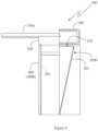
- the housing 200 configures a storage compartment 210 in the second position 200b for storing articles and the storage compartment 210 is accessible to the second-row passengers as shown in figures 4 , 5 , 6 and 7 .
- the front row passengers can access the front storage unit 110 and the second-row passengers can access the storage compartment 210 simultaneously.
- the housing 200 has a lid 220 for covering the storage unit 110.
- the lid 220 is also moveable along with the housing 200 when the housing 200 moves between the first position 200a and the second position 200b.
- the lid 220 is movably arranged on a portion of the housing 200 such that in the first position 200a of the housing 200 the lid 220 pivot around a pivotal axis to provide access to the storage unit 110.
- the lid 220 is pivotally arranged on a top portion of the housing 200.
- the housing 200 has a sidewall portion 202 movable between a stowed position 205a figure 3 and a deployed position 205b when the housing 200 is in the second position 200b.
- the side wall portion 202 is arranged at an inner side portion of the housing 200.
- the housing 200 When the housing 200 is moved rearwards or in the second position 200b, the side wall portion 202 moves to the deployed position 205b away from the inner side portion of the housing 200.
- the housing 200 configures the storage compartment 210 as shown in figures 5 , 6 and 7 .
- the side wall portion 202 flushes to the housing 200 in the stowed position 205a as shown in figure 3 .
- the side wall portion 202 has a corrugated side portion 203 which connects with an inner side wall 204 of the housing 200.
- the corrugated side portion 203 facilitates the movement of the side wall portion 202 between the deployed position 205b and the stowed position 205a.
- the corrugated side portion 203 collapses and facilitates the side wall portion 202 to flush against the inner side wall 204 of the housing 200.
- the movement of the side wall portion 202 can be controlled manually or by means of a motor. In the present embodiment, the side wall portion 202 is moved manually.
- the second-row occupant can remove the articles from the storage compartment 210 and can flushes the side wall portion 202 to the stowed position 205a.
- the side wall portion 202 may have a locking arrangement to keep the side wall portion 202 stay in the stowed position 205a.
- the housing 200 may have a magnetic arrangement to arrest the side wall portion 202 in the stowed position 205a.
- the storage unit 110 may have a secondary storage space to accommodate the side wall portion 202 when the housing 200 slides back to the first position 200a.
- the side wall portion 202 has an articulated structure.
- the side wall portion 202 When the housing 200 is in the first position 200a, the side wall portion 202 is in a collapsible state where the side wall portion 202 is stored on a back side portion of the front storage unit 110.
- the side wall portion 202 collapses and may get stored on the back side portion of the front storage unit 110.
- the housing 200 is slidable on a guide not shown arranged on the floor of the vehicle or on a periphery of the storage unit 110.
- the guide can be a channel or a rail like structure to facilitate the sliding motion of the housing 200 towards the second position 200b. It may be obvious to a person skilled in the art to configure any other obvious arrangement to provide sliding motion to the housing 200.
- the housing 200 can be operated manually or is electrically operable.
- the storage console 100 has an armrest 230 mounted on a top portion of the lid 220.
- the armrest 230 is a foldable unit which is swivellable around a rotational axis.
- the armrest 230 has a first armrest portion 232 and a second armrest portion 234.
- the first armrest portion 232 and the second armrest portion 234 are substantially flat members which are adjoined together on a side portion. Specifically, the first armrest portion 232 and the second armrest portion 234 are pivotally connected to the side portion such that the first armrest portion 232 is foldable over the second armrest portion 234.
- the first armrest portion 232 When the first armrest portion 232 is unfolded, the first armrest portion 232 aligns in the same plane of the second armrest portion 234 configuring a rectangular tray 230a for holding articles as shown in figures 5 , 6 and 7 .
- the tray can be used for holding a laptop or book or bottles or glasses.
- the storage console 100 includes a locking and unlocking unit not shown.
- the locking unit locks the position of the housing 200 according to the user requirement. Specifically, the locking unit may prevent the sliding movement of the housing 200 when the storage compartment 210 is used by the occupants.
- the locking unit may be a manual push lock or electrically driven lock or the like. When the storage compartment 210 is not in use, the occupant can unlock the position of the housing 200 to slide back the housing 200 towards the first position 200a.
- the housing 200 can be movable manually or is electrically operable.
- the storage console 100 has a handle to push or pull the housing 200 in between the first position 200a and the second position 200b.
- the housing 200 is electrically operable.
- the console unit 100 includes two storage units 110, 120 as shown in figures 2 and 3 . Both the storage units 110, 120 are partially covered by housings 200, 300. Each housing 200, 300 can be pulled separately between a first position 200a and a second position 200b to configure respective storage compartments. Each storage compartments can be accessible to the rear row passengers. Further, each storage units 110, 120 can be accessible by lifting respective armrests 230, 240.
- the advantage of the present invention is to provide a storage console for a vehicle with two storage compartments accessible simultaneous to front row passengers and rear row passengers.
- the storage console has a foldable armrest unit to configure a tray to hold articles such as laptop, book and the like. It has a compact arrangement to configure the storage compartment for the rear row passengers. Also, the storage console has a simple mechanism for easy operation.
Landscapes
- Engineering & Computer Science (AREA)
- Mechanical Engineering (AREA)
- Vehicle Step Arrangements And Article Storage (AREA)
Claims (12)
- Aufbewahrungskonsole (100) für ein Fahrzeug, umfassend:mindestens eine Aufbewahrungseinheit (110), die einen Stauraum zur Aufbewahrung von Gegenständen darin enthält und angrenzend an/neben einem Vordersitz des Fahrzeugs angeordnet werden kann;ein Gehäuse (200), das die Aufbewahrungseinheit (110) mindestens teilweise umschließt, wobei das Gehäuse (200) verschiebbar an/über der Aufbewahrungseinheit (110) angeordnet ist, sodass es linear entlang einer Längsebene der Aufbewahrungseinheit (110) zwischen einer ersten Position (200a) und einer zweiten Position (200b) verschiebbar ist.wobei das Gehäuse (200) einen Deckel (220) zum Abdecken der Aufbewahrungseinheit (110) aufweist, wobei der Deckel (220) auch zusammen mit dem Gehäuse (200) beweglich ist, wenn sich das Gehäuse (200) zwischen der ersten Position (200a) und der zweiten Position (200b) bewegt, dadurch gekennzeichnet, dass der Deckel (220) so beweglich auf einem Teil des Gehäuses (200) angeordnet ist, dass der Deckel (220) in der ersten Position (200a) des Gehäuses (200) um eine Drehachse schwenkt, um Zugang zur Aufbewahrungseinheit (110) zu ermöglichen.
- Aufbewahrungskonsole (100) nach Anspruch 1, wobei das Gehäuse (200) einen Seitenwandabschnitt (202) aufweist, der sich zwischen einer Verstauposition (205a) und einer ausgezogenen Position (205b) bewegen lässt, wenn sich das Gehäuse (200) in der zweiten Position (200b) befindet, wobei der Seitenwandabschnitt (202) in der ausgezogenen Position (205b) ein Aufbewahrungsfach (210) bildet und der Seitenwandabschnitt (202) in der Verstauposition (205a) mit dem Gehäuse (200) bündig ist.
- Aufbewahrungskonsole (100) nach Anspruch 1, wobei eine Armlehne (230) an einem oberen Abschnitt des Deckels (220) angebracht ist, wobei die Armlehne (230) eine klappbare Einheit ist, die um eine Drehachse schwenkbar ist.
- Aufbewahrungskonsole (100) nach Anspruch 3, wobei die Armlehne (230) einen ersten Armlehnenteil (232) und einen zweiten Armlehnenteil (234) aufweist, wobei der erste Armlehnenteil (232) und der zweite Armlehnenteil (234) drehbar verbunden sind, sodass der erste Armlehnenteil (232) über den zweiten Armlehnenteil (234) klappbar ist.
- Aufbewahrungskonsole (100) nach Anspruch 4, wobei, wenn der erste Armlehnenteil (232) umgeklappt ist, der erste Armlehnenteil (232) in der gleichen Ebene wie der zweite Armlehnenteil (234) ausgerichtet ist, wodurch eine rechteckige Ablage zur Aufnahme von Gegenständen gebildet wird.
- Aufbewahrungskonsole (100) nach Anspruch 2, wobei, wenn das Gehäuse (200) nach hinten oder in die zweite Position (200b) bewegt wird, sich der Seitenwandabschnitt (202) weg von einem inneren Seitenabschnitt des Gehäuses (200) in die ausgezogene Position (205b) bewegt, wobei das Gehäuse (200) in der ausgezogenen Position (205b) des Seitenwandabschnitts (202) das Aufbewahrungsfach (210) ausbildet.
- Aufbewahrungskonsole (100) nach Anspruch 2, wobei der Seitenwandabschnitt (202) in der Verstauposition (205a) bündig mit der inneren Seitenwand (204) des Gehäuses (200) abschließt.
- Aufbewahrungskonsole (100) nach Anspruch 7, wobei der Seitenwandabschnitt (202) einen gewellten Seitenabschnitt (203) aufweist, der mit dem inneren Abschnitt des Gehäuses (200) verbunden ist, wobei der gewellte Seitenabschnitt (203) die Bewegung des Seitenwandabschnitts (202) zwischen der ausgezogenen Position (205b) und der Verstauposition (205a) erleichtert.
- Aufbewahrungskonsole (100) nach einem der vorhergehenden Ansprüche, wobei, in der Verstauposition (205a), der gewellte Seitenabschnitt (203) zusammengeklappt ist und es so ermöglicht, dass der Seitenwandabschnitt (202) mit der inneren Seitenwand (204) des Gehäuses (200) bündig ist.
- Aufbewahrungskonsole (100) nach einem der vorhergehenden Ansprüche, wobei der Seitenwandabschnitt (202) eine Verriegelungsanordnung aufweist, um den Seitenwandabschnitt (202) in der Verstauposition (205a) zu arretieren.
- Aufbewahrungskonsole (100) nach einem der vorhergehenden Ansprüche, wobei das Gehäuse (200) auf einer am Fahrzeugboden oder an einem Umfang der Aufbewahrungseinheit (110) angeordneten Führung verschiebbar ist.
- Aufbewahrungskonsole (100) nach einem der vorhergehenden Ansprüche, wobei die Aufbewahrungskonsole (100) eine Verriegelungs- und eine Entriegelungseinheit aufweist, wobei die Verriegelungseinheit die Position des Gehäuses (200) verriegelt und die Gleitbewegung des Gehäuses (200) verhindert, wenn das Aufbewahrungsfach (210) in Gebrauch ist.
Applications Claiming Priority (1)
| Application Number | Priority Date | Filing Date | Title |
|---|---|---|---|
| IN202221056084 | 2022-09-29 |
Publications (2)
| Publication Number | Publication Date |
|---|---|
| EP4349655A1 EP4349655A1 (de) | 2024-04-10 |
| EP4349655B1 true EP4349655B1 (de) | 2025-06-18 |
Family
ID=88147099
Family Applications (1)
| Application Number | Title | Priority Date | Filing Date |
|---|---|---|---|
| EP23198963.3A Active EP4349655B1 (de) | 2022-09-29 | 2023-09-22 | Ablagekonsole für ein fahrzeug |
Country Status (2)
| Country | Link |
|---|---|
| US (1) | US20240109496A1 (de) |
| EP (1) | EP4349655B1 (de) |
Families Citing this family (2)
| Publication number | Priority date | Publication date | Assignee | Title |
|---|---|---|---|---|
| US12043155B2 (en) * | 2022-09-14 | 2024-07-23 | Ford Global Technologies, Llc | Vehicle console having deployable table |
| US12427928B2 (en) * | 2022-12-21 | 2025-09-30 | Ford Global Technologies, Llc | Vehicle console having removable module |
Family Cites Families (5)
| Publication number | Priority date | Publication date | Assignee | Title |
|---|---|---|---|---|
| JPS57120145U (de) * | 1981-01-22 | 1982-07-26 | ||
| US7770954B2 (en) * | 2008-09-23 | 2010-08-10 | Faurecia Interior Systems, Inc. | Console assembly for a vehicle |
| FR2937294B1 (fr) * | 2008-10-16 | 2010-11-19 | Peugeot Citroen Automobiles Sa | Dispositif de rangement pour un vehicule. |
| US8100454B2 (en) * | 2008-12-22 | 2012-01-24 | Faurecia Interior Systems, Inc. | C-shaped console assembly for use in a vehicle |
| GB201403769D0 (en) * | 2014-03-04 | 2014-04-16 | Ford Global Tech Llc | A storage assembly for a motor vehicle |
-
2023
- 2023-09-22 EP EP23198963.3A patent/EP4349655B1/de active Active
- 2023-09-29 US US18/375,258 patent/US20240109496A1/en active Pending
Also Published As
| Publication number | Publication date |
|---|---|
| US20240109496A1 (en) | 2024-04-04 |
| EP4349655A1 (de) | 2024-04-10 |
Similar Documents
| Publication | Publication Date | Title |
|---|---|---|
| US7201426B2 (en) | Vehicle seating apparatus | |
| CN108215969B (zh) | 一种用于车辆的肘靠的可操作托盘工作台 | |
| US6921118B2 (en) | Sliding and nesting console system | |
| US20080169668A1 (en) | Vehicle trunk internal storage compartment structure | |
| EP2753496B1 (de) | Verstaubare sitzanordnung für kraftfahrzeuge | |
| EP1536981B1 (de) | Bodenkonsole | |
| US7445261B2 (en) | Console assembly for a vehicle | |
| EP1176060B1 (de) | Rekonfigurierbare Zwischenwand für ein Kraftfahrzeug | |
| US9211848B2 (en) | Storage unit for a motor vehicle | |
| US6626481B2 (en) | Vehicular seat system | |
| EP4349655A1 (de) | Ablagekonsole für ein fahrzeug | |
| US10639971B2 (en) | Vehicle furniture system | |
| US7891623B2 (en) | Stowable cup holder tray assembly | |
| US4270790A (en) | Convertible seat and storage device for automobiles | |
| US20070085363A1 (en) | Console assembly for a vehicle | |
| CN119142266A (zh) | 具有可展开的装置保持器的车辆控制台 | |
| US20080007079A1 (en) | Console assembly for a vehicle | |
| WO2000013931A1 (en) | Vehicle seat with a seat back having a fixed outer structure and an inner pass-through | |
| US20230125485A1 (en) | Table device | |
| US10589652B2 (en) | Mechanized tray table assembly | |
| EP1787856B1 (de) | Aufbewahrungsvorrichtung | |
| CN220430023U (zh) | 一种扶手箱及车辆 | |
| US12617325B2 (en) | Support device for an aircraft cabin interior layout assembly, related assembly and method | |
| JP4332827B2 (ja) | 車両の後部荷室構造 | |
| CN114347908A (zh) | 一种扶手箱及车辆 |
Legal Events
| Date | Code | Title | Description |
|---|---|---|---|
| PUAI | Public reference made under article 153(3) epc to a published international application that has entered the european phase |
Free format text: ORIGINAL CODE: 0009012 |
|
| STAA | Information on the status of an ep patent application or granted ep patent |
Free format text: STATUS: THE APPLICATION HAS BEEN PUBLISHED |
|
| AK | Designated contracting states |
Kind code of ref document: A1 Designated state(s): AL AT BE BG CH CY CZ DE DK EE ES FI FR GB GR HR HU IE IS IT LI LT LU LV MC ME MK MT NL NO PL PT RO RS SE SI SK SM TR |
|
| STAA | Information on the status of an ep patent application or granted ep patent |
Free format text: STATUS: REQUEST FOR EXAMINATION WAS MADE |
|
| 17P | Request for examination filed |
Effective date: 20241010 |
|
| RBV | Designated contracting states (corrected) |
Designated state(s): AL AT BE BG CH CY CZ DE DK EE ES FI FR GB GR HR HU IE IS IT LI LT LU LV MC ME MK MT NL NO PL PT RO RS SE SI SK SM TR |
|
| GRAP | Despatch of communication of intention to grant a patent |
Free format text: ORIGINAL CODE: EPIDOSNIGR1 |
|
| STAA | Information on the status of an ep patent application or granted ep patent |
Free format text: STATUS: GRANT OF PATENT IS INTENDED |
|
| INTG | Intention to grant announced |
Effective date: 20250205 |
|
| GRAS | Grant fee paid |
Free format text: ORIGINAL CODE: EPIDOSNIGR3 |
|
| GRAA | (expected) grant |
Free format text: ORIGINAL CODE: 0009210 |
|
| STAA | Information on the status of an ep patent application or granted ep patent |
Free format text: STATUS: THE PATENT HAS BEEN GRANTED |
|
| AK | Designated contracting states |
Kind code of ref document: B1 Designated state(s): AL AT BE BG CH CY CZ DE DK EE ES FI FR GB GR HR HU IE IS IT LI LT LU LV MC ME MK MT NL NO PL PT RO RS SE SI SK SM TR |
|
| REG | Reference to a national code |
Ref country code: GB Ref legal event code: FG4D |
|
| REG | Reference to a national code |
Ref country code: CH Ref legal event code: EP |
|
| REG | Reference to a national code |
Ref country code: DE Ref legal event code: R096 Ref document number: 602023004068 Country of ref document: DE |
|
| REG | Reference to a national code |
Ref country code: CH Ref legal event code: EP |
|
| REG | Reference to a national code |
Ref country code: IE Ref legal event code: FG4D |
|
| PG25 | Lapsed in a contracting state [announced via postgrant information from national office to epo] |
Ref country code: FI Free format text: LAPSE BECAUSE OF FAILURE TO SUBMIT A TRANSLATION OF THE DESCRIPTION OR TO PAY THE FEE WITHIN THE PRESCRIBED TIME-LIMIT Effective date: 20250618 |
|
| PGFP | Annual fee paid to national office [announced via postgrant information from national office to epo] |
Ref country code: DE Payment date: 20250820 Year of fee payment: 3 |
|
| REG | Reference to a national code |
Ref country code: LT Ref legal event code: MG9D |
|
| PG25 | Lapsed in a contracting state [announced via postgrant information from national office to epo] |
Ref country code: NO Free format text: LAPSE BECAUSE OF FAILURE TO SUBMIT A TRANSLATION OF THE DESCRIPTION OR TO PAY THE FEE WITHIN THE PRESCRIBED TIME-LIMIT Effective date: 20250918 Ref country code: GR Free format text: LAPSE BECAUSE OF FAILURE TO SUBMIT A TRANSLATION OF THE DESCRIPTION OR TO PAY THE FEE WITHIN THE PRESCRIBED TIME-LIMIT Effective date: 20250919 |
|
| PG25 | Lapsed in a contracting state [announced via postgrant information from national office to epo] |
Ref country code: BG Free format text: LAPSE BECAUSE OF FAILURE TO SUBMIT A TRANSLATION OF THE DESCRIPTION OR TO PAY THE FEE WITHIN THE PRESCRIBED TIME-LIMIT Effective date: 20250618 |
|
| PG25 | Lapsed in a contracting state [announced via postgrant information from national office to epo] |
Ref country code: HR Free format text: LAPSE BECAUSE OF FAILURE TO SUBMIT A TRANSLATION OF THE DESCRIPTION OR TO PAY THE FEE WITHIN THE PRESCRIBED TIME-LIMIT Effective date: 20250618 |
|
| PGFP | Annual fee paid to national office [announced via postgrant information from national office to epo] |
Ref country code: FR Payment date: 20250821 Year of fee payment: 3 Ref country code: AT Payment date: 20251020 Year of fee payment: 3 |
|
| PG25 | Lapsed in a contracting state [announced via postgrant information from national office to epo] |
Ref country code: RS Free format text: LAPSE BECAUSE OF FAILURE TO SUBMIT A TRANSLATION OF THE DESCRIPTION OR TO PAY THE FEE WITHIN THE PRESCRIBED TIME-LIMIT Effective date: 20250918 |
|
| REG | Reference to a national code |
Ref country code: NL Ref legal event code: MP Effective date: 20250618 |
|
| PG25 | Lapsed in a contracting state [announced via postgrant information from national office to epo] |
Ref country code: LV Free format text: LAPSE BECAUSE OF FAILURE TO SUBMIT A TRANSLATION OF THE DESCRIPTION OR TO PAY THE FEE WITHIN THE PRESCRIBED TIME-LIMIT Effective date: 20250618 |
|
| PG25 | Lapsed in a contracting state [announced via postgrant information from national office to epo] |
Ref country code: NL Free format text: LAPSE BECAUSE OF FAILURE TO SUBMIT A TRANSLATION OF THE DESCRIPTION OR TO PAY THE FEE WITHIN THE PRESCRIBED TIME-LIMIT Effective date: 20250618 |
|
| PG25 | Lapsed in a contracting state [announced via postgrant information from national office to epo] |
Ref country code: PT Free format text: LAPSE BECAUSE OF FAILURE TO SUBMIT A TRANSLATION OF THE DESCRIPTION OR TO PAY THE FEE WITHIN THE PRESCRIBED TIME-LIMIT Effective date: 20251020 |
|
| REG | Reference to a national code |
Ref country code: AT Ref legal event code: MK05 Ref document number: 1803924 Country of ref document: AT Kind code of ref document: T Effective date: 20250618 |
|
| PG25 | Lapsed in a contracting state [announced via postgrant information from national office to epo] |
Ref country code: IS Free format text: LAPSE BECAUSE OF FAILURE TO SUBMIT A TRANSLATION OF THE DESCRIPTION OR TO PAY THE FEE WITHIN THE PRESCRIBED TIME-LIMIT Effective date: 20251018 |
|
| PG25 | Lapsed in a contracting state [announced via postgrant information from national office to epo] |
Ref country code: AT Free format text: LAPSE BECAUSE OF FAILURE TO SUBMIT A TRANSLATION OF THE DESCRIPTION OR TO PAY THE FEE WITHIN THE PRESCRIBED TIME-LIMIT Effective date: 20250618 Ref country code: SM Free format text: LAPSE BECAUSE OF FAILURE TO SUBMIT A TRANSLATION OF THE DESCRIPTION OR TO PAY THE FEE WITHIN THE PRESCRIBED TIME-LIMIT Effective date: 20250618 |
|
| PG25 | Lapsed in a contracting state [announced via postgrant information from national office to epo] |
Ref country code: CZ Free format text: LAPSE BECAUSE OF FAILURE TO SUBMIT A TRANSLATION OF THE DESCRIPTION OR TO PAY THE FEE WITHIN THE PRESCRIBED TIME-LIMIT Effective date: 20250618 |
|
| PG25 | Lapsed in a contracting state [announced via postgrant information from national office to epo] |
Ref country code: PL Free format text: LAPSE BECAUSE OF FAILURE TO SUBMIT A TRANSLATION OF THE DESCRIPTION OR TO PAY THE FEE WITHIN THE PRESCRIBED TIME-LIMIT Effective date: 20250618 |
|
| PG25 | Lapsed in a contracting state [announced via postgrant information from national office to epo] |
Ref country code: EE Free format text: LAPSE BECAUSE OF FAILURE TO SUBMIT A TRANSLATION OF THE DESCRIPTION OR TO PAY THE FEE WITHIN THE PRESCRIBED TIME-LIMIT Effective date: 20250618 |
|
| PG25 | Lapsed in a contracting state [announced via postgrant information from national office to epo] |
Ref country code: SK Free format text: LAPSE BECAUSE OF FAILURE TO SUBMIT A TRANSLATION OF THE DESCRIPTION OR TO PAY THE FEE WITHIN THE PRESCRIBED TIME-LIMIT Effective date: 20250618 |
|
| PG25 | Lapsed in a contracting state [announced via postgrant information from national office to epo] |
Ref country code: ES Free format text: LAPSE BECAUSE OF FAILURE TO SUBMIT A TRANSLATION OF THE DESCRIPTION OR TO PAY THE FEE WITHIN THE PRESCRIBED TIME-LIMIT Effective date: 20250618 |
|
| PG25 | Lapsed in a contracting state [announced via postgrant information from national office to epo] |
Ref country code: RO Free format text: LAPSE BECAUSE OF FAILURE TO SUBMIT A TRANSLATION OF THE DESCRIPTION OR TO PAY THE FEE WITHIN THE PRESCRIBED TIME-LIMIT Effective date: 20250618 |
|
| REG | Reference to a national code |
Ref country code: DE Ref legal event code: R097 Ref document number: 602023004068 Country of ref document: DE |
|
| PG25 | Lapsed in a contracting state [announced via postgrant information from national office to epo] |
Ref country code: DK Free format text: LAPSE BECAUSE OF FAILURE TO SUBMIT A TRANSLATION OF THE DESCRIPTION OR TO PAY THE FEE WITHIN THE PRESCRIBED TIME-LIMIT Effective date: 20250618 |
|
| PG25 | Lapsed in a contracting state [announced via postgrant information from national office to epo] |
Ref country code: IT Free format text: LAPSE BECAUSE OF FAILURE TO SUBMIT A TRANSLATION OF THE DESCRIPTION OR TO PAY THE FEE WITHIN THE PRESCRIBED TIME-LIMIT Effective date: 20250618 |
|
| PLBE | No opposition filed within time limit |
Free format text: ORIGINAL CODE: 0009261 |
|
| STAA | Information on the status of an ep patent application or granted ep patent |
Free format text: STATUS: NO OPPOSITION FILED WITHIN TIME LIMIT |
|
| REG | Reference to a national code |
Ref country code: CH Ref legal event code: L10 Free format text: ST27 STATUS EVENT CODE: U-0-0-L10-L00 (AS PROVIDED BY THE NATIONAL OFFICE) Effective date: 20260430 |