EP4350093A1 - Dispositif de fixation, ensemble de fixation et procédé de montage - Google Patents
Dispositif de fixation, ensemble de fixation et procédé de montage Download PDFInfo
- Publication number
- EP4350093A1 EP4350093A1 EP23197411.4A EP23197411A EP4350093A1 EP 4350093 A1 EP4350093 A1 EP 4350093A1 EP 23197411 A EP23197411 A EP 23197411A EP 4350093 A1 EP4350093 A1 EP 4350093A1
- Authority
- EP
- European Patent Office
- Prior art keywords
- wall
- holding
- holding means
- fastening device
- rod
- Prior art date
- Legal status (The legal status is an assumption and is not a legal conclusion. Google has not performed a legal analysis and makes no representation as to the accuracy of the status listed.)
- Pending
Links
Images

Classifications
-
- E—FIXED CONSTRUCTIONS
- E03—WATER SUPPLY; SEWERAGE
- E03D—WATER-CLOSETS OR URINALS WITH FLUSHING DEVICES; FLUSHING VALVES THEREFOR
- E03D11/00—Other component parts of water-closets, e.g. noise-reducing means in the flushing system, flushing pipes mounted in the bowl, seals for the bowl outlet, devices preventing overflow of the bowl contents; devices forming a water seal in the bowl after flushing, devices eliminating obstructions in the bowl outlet or preventing backflow of water and excrements from the waterpipe
- E03D11/13—Parts or details of bowls; Special adaptations of pipe joints or couplings for use with bowls, e.g. provisions in bowl construction preventing backflow of waste-water from the bowl in the flushing pipe or cistern, provisions for a secondary flushing, for noise-reducing
- E03D11/14—Means for connecting the bowl to the wall, e.g. to a wall outlet
Definitions
- the invention relates to a fastening device for a wall-mounted sanitary object.
- a fastening device for a wall-mounted sanitary object.
- This can be, for example, a wall-mounted toilet that is fastened to two threaded rods that protrude from the wall.
- holding elements are provided that are firmly connected to the threaded rods and each have a clamping device.
- the clamping device can generate a holding force that presses the toilet against the wall.
- a fastening device is made, for example, of EP 2 150 657 A1 known, which goes back to the applicant.
- the well-known fastening device has proven itself to be extremely effective and enables the toilet to be attached to the wall quickly and securely by a single fitter.
- the holding elements cannot be positioned in the desired way, making it difficult to attach the toilet. Since the holding elements disappear into the sanitary object during installation, it is difficult for the fitter to see whether the holding elements are positioned correctly.
- the invention is based on the object of improving the known fastening device for a wall-mounted sanitary object in such a way that the proven quick and secure fastening of the sanitary object is easily possible even under difficult conditions.
- the invention is also based on the object of specifying a set for fastening a sanitary object and an assembly method.
- the object is achieved according to the invention by the subject matter of claim 1, with regard to the set by the subject matter of claim 9 and with regard to the assembly method by the subject matter of claim 10.
- the object is achieved according to the invention by a fastening device for a wall-mounted sanitary object, in particular a wall-mounted toilet, which has holding elements for holding the sanitary object.
- the holding elements are firmly connected to rods that protrude from the wall.
- the holding elements each have a clamping means for applying a holding force that presses the sanitary object against the wall during use.
- the holding elements are each clamped between a first holding means close to the wall and a second holding means remote from the wall.
- the first and second holding means are connected to the respective rod.
- the first holding means i.e. the holding means close to the wall, is spaced from the wall to form a gap between the respective holding element and the wall.
- the invention has the advantage that the holding elements, also called brackets, are not pressed against the wall, but are fixed at a distance from the wall by the two holding devices.
- the position of the holding elements on the rods is therefore independent of the nature of the wall. This enables the fitter to pre-mount the holding elements on the rods at approximately the same height in order to achieve secure and quick fastening of the sanitary object even on uneven walls.
- the tried and tested fastening principle using the clamping device can be retained because the bearing force required for clamping is made possible by the fastening of the holding elements to the rod using the holding devices.
- the holding force generated by the clamping device is introduced via the holding devices into the respective rod and thus into the wall without the holding elements having to be in contact with the wall. This solution is simple and effective.
- the first holding means near the wall is understood to be the holding means that is arranged closer to the wall compared to the second holding means.
- the second holding means farther from the wall is the holding means that is further away from the wall compared to the first holding means near the wall.
- the holding means near the wall can also be referred to as the wall-side holding means or, when looking away from the wall, as the proximal holding means.
- the holding means farther from the wall can be referred to as the distal holding means when looking away from the wall.
- the rod can preferably be a threaded rod with an external thread. Other rods are possible.
- the first and/or second holding means can be movable on the rod for clamping, in particular axially movable. This makes it easy to determine and fix the position of the holding element.
- both holding means can be movable on the rod for clamping.
- both holding means can be designed as nuts, for example, which are screwed onto the rod, which in this case is designed as a threaded rod, and clamp the holding element. This design is simple and allows flexible assembly.
- only the first or only the second holding means can be movable on the rod for clamping.
- the other holding means is fixedly connected to the rod.
- the rod can have a fixed stop that forms one of the two holding means.
- the associated other holding means is movable for fixing, e.g. a nut.
- the holding elements each have a component wall, in particular a rear wall or another transverse wall of the holding element, which extends transversely to the respective rod.
- the component wall, in particular the rear wall has an opening for the rod to pass through, wherein the holding means rest against the component wall on both sides in the assembled state. The holding means therefore clamp the component wall of the holding element and thus fix the holding element on the rod.
- the opening in the component wall for the passage of the rod can, for example, be a bore adapted to the outer cross-section of the rod or a correspondingly adapted slot which is moved transversely to the rod for mounting.
- the rods are each connected to a spacer that is arranged in the gap between the wall and the respective holding element.
- the spacer can be a spacer sleeve, for example. This has the advantage that the distance between the wall and the holding element does not have to be measured.
- a further preferred embodiment consists in arranging the spacer loosely in the gap between the wall and the respective holding element in the final assembled state, so that a further aid for leveling any unevenness in the wall can be arranged between the wall and the spacer.
- the aid can be, for example, a rod that is long enough to rest against flat surfaces of the wall and bridge any unevenness in between, so that the two holding elements are arranged essentially at the same height. It goes without saying that the two spacers are the same length in this case. Other aids, such as a template, are possible.
- the gap between the wall and the respective support element is free of installations. This has the advantage that the number of components is reduced. In this case, the distance between the support element and the wall is measured. If necessary, an aid such as a rod can be used for this purpose, which rests against flat surfaces of the wall and serves as a reference point for the measurement.
- a cross-connecting piece is arranged between the holding elements, which connects the two holding elements. This ensures that the holding elements are correctly aligned in the circumferential direction of the rod, so that the toilet can be mounted on the holding elements quickly and easily.
- a set for fastening a wall-mounted sanitary object in particular a wall-mounted toilet
- the set is claimed in the unassembled state, i.e. in the form in which the set is attached to the sanitary object to be assembled for use by a fitter.
- the set has holding elements for Holding the sanitary object.
- the holding elements are suitable and intended to be firmly connected to the rods that protrude from the wall for mounting the sanitary object.
- the rods in the set are not the subject of the invention.
- the holding elements each have a clamping device for applying a holding force that presses the sanitary object against the wall when installed.
- the set includes first and second holding devices for clamping the holding elements. When installed, the first holding device is arranged close to the wall and the second holding device is arranged away from the wall.
- the first holding means and the second holding means can be connected to the respective rod.
- the first holding means In the assembled state, the first holding means can be positioned or is positioned at a distance from the wall to form a gap between the respective holding element and the wall.
- first holding means In the case of a stationary, i.e. firmly connected to the rod, first holding means, this is positioned at a distance from the wall in the assembled state.
- a movable, i.e. non-stationary first holding means this can be positioned (positionable) in the pre-assembled state to adjust the distance from the wall.
- the first holding means In the fully assembled state, the first holding means is also firmly arranged on the rod.
- the claimed assembly method is specifically a method for fastening a wall-mounted sanitary object with a fastening device according to the invention or a set according to the invention.
- an assembly aid for adjusting the distances between the holding elements and the wall is temporarily arranged in the gap between the respective holding element and the wall.
- the assembly aid protrudes in the transverse direction to the rods at least on one side beyond a rod, in particular on both sides beyond the rods.
- the assembly aid rests on flat surfaces, such as tiled surfaces of the wall, on at least one side, preferably on both sides.
- the assembly aid therefore has a fixed position running parallel to the wall, at which the holding elements can be aligned so that they are arranged at the same height in the final assembled state.
- the assembly aid can be, for example, a rod, in particular a meter stick, or a template.
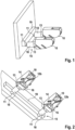
- the fastening device according to Fig.1 is designed for a wall-mounted toilet.
- Other sanitary objects, such as urinals, can also be mounted using the fastening device.
- the fastening device is shown and claimed in the assembled state.
- the components of the fastening device are disclosed and claimed as part of a set, i.e. in the state before assembly. These components are included with the sanitary object to be attached and are used by the fitter for assembly.
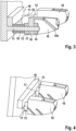
- the fastening device has holding elements 10 that hold the sanitary object (not shown here).
- the holding elements 10 are also referred to as brackets or holding blocks. As in Fig.1 As can be clearly seen, the holding elements 10 are firmly connected to rods 11, in particular threaded rods, which protrude from the wall. The rods 11 bear the weight of the sanitary object.
- the holding elements 10 each have a clamping device 12a, 12b, which in use serves to apply the holding force with which the sanitary object is pressed against the wall in the mounted state.
- the clamping device 12a, 12b is in principle for example from the above-mentioned EP 2 150 657 A1 and has a carriage 12a which can be moved along inclined guides 12b.
- the inclined guides 12b are for example in Fig.2
- the carriage 12a is in the embodiment according to Fig.5 This or another carriage can also be used in the embodiment shown in Figures 1 to 3 or in the embodiment according to Fig.4 be used.
- a screw system (not shown) is provided, which engages with the slide 12a and pulls the slide 12a upwards. This generates the desired holding force due to the inclined guide 12b, which presses the sanitary object against the wall and connects it to the respective holding element 10.
- the screw system has an adapter or cage that is provided for fastening a toilet lid (not shown). This fastening principle is known from the above-mentioned prior art and will not be explained further here.
- the holding elements 10 are each clamped between a first holding means 13 close to the wall and a second holding means 14 remote from the wall.
- the holding means 13, 14 are designed as nuts that are screwed onto the external thread of the rods 11.
- Other holding means 13, 14 are possible.
- the first holding means 13 is spaced from the wall and thereby forms a gap 15 that extends between the respective holding element 10 and the wall. This ensures that the nature of the wall, for example any unevenness, has no influence on the position of the holding elements, so that the sanitary object can be installed safely and quickly even under less than optimal conditions.
- the connection of the two holding means 13, 14 to the rod 11 ensures that the bearing force required to apply the holding force is introduced into the rods 11 and thus into the wall. The sanitary object can therefore be mounted safely without the condition of the wall having a negative impact on the fastening.
- Both holding means 13, 14 are axially movable for clamping and positioning the respective holding element 10 on the rod 11. In the specific example, this is done by turning the nuts accordingly.
- FIG.5 Another example is in Fig.5 There it is shown that the first holding means 13, which is close to the wall, is arranged stationary relative to the wall, i.e. immovable. To clamp the holding element 10, the second holding means 14 is movable on the rod. In the example according to Fig.5 the second holding means 14 is a nut.
- the first holding means 13 is in the example according to Fig.5 designed as a sleeve with a stop.
- the sleeve has a shaft with an internal thread.
- the shaft with the internal thread can be screwed onto the threaded rod and, when fully screwed in, defines a stationary stop which forms a fixed gap 15 between the respective holding element 10 and the wall.
- the slide 12a of the clamping device is also shown, which is moved on the inclined guide 12b.
- the slide 12a has an internal thread through which the screw (not shown) for operating the slide 12a is guided.
- the respective holding element 10 has a component wall 16 that extends transversely to the respective rod 11.
- the component wall 16 is the rear wall of the holding element 10, which faces the wall when assembled.
- Other transverse walls of the holding element 10 can also be used for clamping.
- the component wall 16 has an opening 17 through which the rod 11 is guided in the assembled state.
- the opening is designed as a bore.
- Other openings, for example slots, are possible.
- the two holding means 13, 14 rest on both sides on the component wall 16 and are clamped against it.
- the first holding means 13 near the wall for a tool for example a wrench, is freely accessible.
- a spacer 18 is provided, which is arranged in the gap 15 between the wall and the respective holding element 10.
- the spacer 18 can, for example, be designed as a sleeve that is pushed over the rod 11.
- the sleeves or spacers 18 are of the same length.
- an assembly aid 19 which rests against the wall and crosses the two rods 11.
- the assembly aid can be, for example, a meter stick or folding rule or a template or another elongated component that is long enough to extend into an area of the wall that is suitable as a reference surface.
- a tiled area of the wall can form a suitable reference surface for adjusting the distance via the spacers 18.
- the assembly aid 19 is long enough to extend into the tiled area of the wall on both sides of the rods 11, so that the assembly aid 19 extends essentially parallel to the wall regardless of any unevenness between the rods 11. This ensures that the distance of the two holding elements 10 from the wall is essentially the same.
- the two spacers 18 are not provided, ie the gap 15 is essentially free of installations (except for the rods 11 and the first wall-near holding means 13).
- the assembly aid 19 is arranged in such a way that the first two wall-near holding means 13 are directly in contact with the assembly aid 19. The principle of spacing the two holding elements 10 from the wall is, as in the example according to Figures 1 to 3 , retained.
- a cross-connecting piece which, in the assembled state, is arranged between the holding elements 10 and connects them.
- the cross-connecting piece serves to fix the two holding elements 10 on the rods correctly aligned in the circumferential direction so that the upper sides of the holding elements 10 are arranged substantially horizontally for mounting the sanitary object.
- the assembly method works in such a way that the assembly aid 19 is first arranged on the two rods 11 and aligned parallel to the wall with the aid of the tiled areas. Then the spacers 18 or the first holding means 13 near the wall are positioned so that they rest either directly or via the spacers 18 on the assembly aid 19 so that they are spaced a predetermined distance from the wall. The holding elements 10 are then pushed onto the rods 11 up to the first holding means, which serves as a positioning stop. The holding elements 10 or the corresponding component walls 16 of the holding elements 10 are then fixed or clamped by the second holding means 14 remote from the wall.
- the embodiment according to Fig.5 is mounted in a similar manner, whereby, in contrast to the previous embodiments, the first holding means 13 close to the wall is arranged in a stationary manner.
Landscapes
- Health & Medical Sciences (AREA)
- Life Sciences & Earth Sciences (AREA)
- Engineering & Computer Science (AREA)
- Hydrology & Water Resources (AREA)
- Public Health (AREA)
- Water Supply & Treatment (AREA)
- Supports Or Holders For Household Use (AREA)
- Sanitary Device For Flush Toilet (AREA)
Applications Claiming Priority (1)
| Application Number | Priority Date | Filing Date | Title |
|---|---|---|---|
| DE102022124822.4A DE102022124822A1 (de) | 2022-09-27 | 2022-09-27 | Befestigungsvorrichtung, Set zum Befestigen und Montageverfahren |
Publications (1)
| Publication Number | Publication Date |
|---|---|
| EP4350093A1 true EP4350093A1 (fr) | 2024-04-10 |
Family
ID=88068964
Family Applications (1)
| Application Number | Title | Priority Date | Filing Date |
|---|---|---|---|
| EP23197411.4A Pending EP4350093A1 (fr) | 2022-09-27 | 2023-09-14 | Dispositif de fixation, ensemble de fixation et procédé de montage |
Country Status (3)
| Country | Link |
|---|---|
| EP (1) | EP4350093A1 (fr) |
| CN (1) | CN221837691U (fr) |
| DE (1) | DE102022124822A1 (fr) |
Citations (3)
| Publication number | Priority date | Publication date | Assignee | Title |
|---|---|---|---|---|
| EP2150657A1 (fr) | 2007-12-12 | 2010-02-10 | Villeroy & Boch Ag | Dispositif pour fixer un appareil en suspension murale |
| EP3093405A2 (fr) * | 2015-05-11 | 2016-11-16 | Kamil Ridvan Erbil | Appareil de montage de cuvette de toilettes murale |
| EP2390430B1 (fr) * | 2010-05-25 | 2016-12-07 | fischerwerke GmbH & Co. KG | Dispositif de fixation en particulier pour des appareils sanitaires muraux |
-
2022
- 2022-09-27 DE DE102022124822.4A patent/DE102022124822A1/de active Pending
-
2023
- 2023-09-14 EP EP23197411.4A patent/EP4350093A1/fr active Pending
- 2023-09-27 CN CN202322649199.8U patent/CN221837691U/zh active Active
Patent Citations (4)
| Publication number | Priority date | Publication date | Assignee | Title |
|---|---|---|---|---|
| EP2150657A1 (fr) | 2007-12-12 | 2010-02-10 | Villeroy & Boch Ag | Dispositif pour fixer un appareil en suspension murale |
| EP2150657B1 (fr) * | 2007-12-12 | 2011-08-31 | Villeroy & Boch Ag | Dispositif pour fixer un appareil en suspension murale |
| EP2390430B1 (fr) * | 2010-05-25 | 2016-12-07 | fischerwerke GmbH & Co. KG | Dispositif de fixation en particulier pour des appareils sanitaires muraux |
| EP3093405A2 (fr) * | 2015-05-11 | 2016-11-16 | Kamil Ridvan Erbil | Appareil de montage de cuvette de toilettes murale |
Non-Patent Citations (1)
| Title |
|---|
| ANONYMOUS: "Kpepezh SupraFix 3.0 podBechyx yhitazoB Villeroy & Boch", SCANSERVIS, 1 January 2003 (2003-01-01), pages 1 - 3, XP093088314, Retrieved from the Internet <URL:https://scanservis.ru/catalog/zapchasti_dlya_unitazov_i_installyatsly_villeroy_boch/%20krepezh_dlya_podvesnykh_unitazov_villeroy_boch/> [retrieved on 20231004] * |
Also Published As
| Publication number | Publication date |
|---|---|
| CN221837691U (zh) | 2024-10-15 |
| DE102022124822A1 (de) | 2024-03-28 |
Similar Documents
| Publication | Publication Date | Title |
|---|---|---|
| DE102005051336B4 (de) | Verfahren zum Befestigen eines Clamp-on-Durchflussmessgeräts an einem von einem Fluid durchströmbaren Messrohr | |
| EP3472403B1 (fr) | Dispositif servant à fixer un élément en forme de plaque dans une rainure de réception d'un rail de support | |
| DE102015108302A1 (de) | Befestigungselement | |
| WO2014001373A1 (fr) | Dispositif et procédé destinés à fixer et orienter un rail de guidage | |
| DE202021107024U1 (de) | Verstellbarer Kabelbefestigungshalter | |
| DE102008006917B4 (de) | Vorrichtung zur Lageverstellung eines Kabelkanals oder dergleichen | |
| EP3636844A1 (fr) | Cadre de construction sèche pour une porte coulissante | |
| EP4350093A1 (fr) | Dispositif de fixation, ensemble de fixation et procédé de montage | |
| DE112019004011T5 (de) | Montagesystem für ein Kastenprofil | |
| EP2708679B1 (fr) | Dispositif d'aide au montage pour le montage d'une huisserie | |
| DE102017111984A1 (de) | Befestigungsvorrichtung für eine Schleifleitung und Schleifleitungssystem | |
| DE19626205C2 (de) | Kabelanschlußkasten | |
| EP4263411B1 (fr) | Dispositif de fixation de rail pour des sections de rail de guidage d'un escalier roulant ou d'un trottoir roulant | |
| DE202013011471U1 (de) | Vorrichtung zur Befestigung eines Fensters oder einer Tür in einer Wandöffnung | |
| DE202007008150U1 (de) | Befestigungsvorrichtung für Solarmodule | |
| EP3620701B1 (fr) | Attache d'installation | |
| EP3766770B1 (fr) | Guidage de câble pour un vélo | |
| DE102018126385A1 (de) | Halteblech | |
| DE202017103287U1 (de) | Befestigungsvorrichtung für eine Schleifleitung und Schleifleitungssystem | |
| DE202009010497U1 (de) | Winkel zur Befestigung eines Bauelementes | |
| DE102015210538A1 (de) | Befestigungsvorrichtung für Schienen | |
| DE102024127482A1 (de) | Höhenverstellbare Gerätehalterung für Fahrzeugschienen | |
| EP4459135A1 (fr) | Élément de fixation d'un tuyau profilé en forme de t, agencement de connexion doté de l'élément de fixation, appareil de pose et procédé de fabrication et de connexion | |
| EP4435197A1 (fr) | Marquise | |
| DE102023110772A1 (de) | Tuchwellenhalterung |
Legal Events
| Date | Code | Title | Description |
|---|---|---|---|
| PUAI | Public reference made under article 153(3) epc to a published international application that has entered the european phase |
Free format text: ORIGINAL CODE: 0009012 |
|
| STAA | Information on the status of an ep patent application or granted ep patent |
Free format text: STATUS: THE APPLICATION HAS BEEN PUBLISHED |
|
| AK | Designated contracting states |
Kind code of ref document: A1 Designated state(s): AL AT BE BG CH CY CZ DE DK EE ES FI FR GB GR HR HU IE IS IT LI LT LU LV MC ME MK MT NL NO PL PT RO RS SE SI SK SM TR |
|
| STAA | Information on the status of an ep patent application or granted ep patent |
Free format text: STATUS: REQUEST FOR EXAMINATION WAS MADE |
|
| 17P | Request for examination filed |
Effective date: 20241009 |
|
| RBV | Designated contracting states (corrected) |
Designated state(s): AL AT BE BG CH CY CZ DE DK EE ES FI FR GB GR HR HU IE IS IT LI LT LU LV MC ME MK MT NL NO PL PT RO RS SE SI SK SM TR |