EP4350104A1 - Barre de support pour la formation d'une grille - Google Patents
Barre de support pour la formation d'une grille Download PDFInfo
- Publication number
- EP4350104A1 EP4350104A1 EP23202038.8A EP23202038A EP4350104A1 EP 4350104 A1 EP4350104 A1 EP 4350104A1 EP 23202038 A EP23202038 A EP 23202038A EP 4350104 A1 EP4350104 A1 EP 4350104A1
- Authority
- EP
- European Patent Office
- Prior art keywords
- support rod
- cover element
- coupling
- support
- grating
- Prior art date
- Legal status (The legal status is an assumption and is not a legal conclusion. Google has not performed a legal analysis and makes no representation as to the accuracy of the status listed.)
- Granted
Links
Images





Classifications
-
- E—FIXED CONSTRUCTIONS
- E04—BUILDING
- E04C—STRUCTURAL ELEMENTS; BUILDING MATERIALS
- E04C2/00—Building elements of relatively thin form for the construction of parts of buildings, e.g. sheet materials, slabs, or panels
- E04C2/30—Building elements of relatively thin form for the construction of parts of buildings, e.g. sheet materials, slabs, or panels characterised by the shape or structure
- E04C2/42—Gratings; Grid-like panels
- E04C2/421—Gratings; Grid-like panels made of bar-like elements, e.g. bars discontinuous in one direction
- E04C2/422—Gratings; Grid-like panels made of bar-like elements, e.g. bars discontinuous in one direction with continuous bars connecting at crossing points of the grid pattern
- E04C2/425—Gratings; Grid-like panels made of bar-like elements, e.g. bars discontinuous in one direction with continuous bars connecting at crossing points of the grid pattern made of perforated bars
-
- E—FIXED CONSTRUCTIONS
- E04—BUILDING
- E04H—BUILDINGS OR LIKE STRUCTURES FOR PARTICULAR PURPOSES; SWIMMING OR SPLASH BATHS OR POOLS; MASTS; FENCING; TENTS OR CANOPIES, IN GENERAL
- E04H4/00—Swimming or splash baths or pools
- E04H4/12—Devices or arrangements for circulating water, i.e. devices for removal of polluted water, cleaning baths or for water treatment
- E04H4/1209—Treatment of water for swimming pools
- E04H4/1218—Devices for removal of polluted water; Circumferential gutters
- E04H4/1227—Circumferential gutters
-
- E—FIXED CONSTRUCTIONS
- E03—WATER SUPPLY; SEWERAGE
- E03F—SEWERS; CESSPOOLS
- E03F5/00—Sewerage structures
- E03F5/04—Gullies inlets, road sinks, floor drains with or without odour seals or sediment traps
- E03F5/06—Gully gratings
-
- E—FIXED CONSTRUCTIONS
- E04—BUILDING
- E04H—BUILDINGS OR LIKE STRUCTURES FOR PARTICULAR PURPOSES; SWIMMING OR SPLASH BATHS OR POOLS; MASTS; FENCING; TENTS OR CANOPIES, IN GENERAL
- E04H4/00—Swimming or splash baths or pools
- E04H4/06—Safety devices; Coverings for baths
Definitions
- the invention relates to a support rod, a cover element for a support rod and a grating.
- Gratings for example modular overflow gratings for covering overflow channels of swimming pools, or gratings for covering shafts, channels or the like, are well known in the professional world.
- EP3023560B1 or through the CN213869132U Elements for the formation of swimming pool gratings have become known, which are each made up of horizontally connectable or interlocking support bars.
- Gratings are usually used to cover hazardous areas, such as gutters, channels, pits, ditches and the like. It is important to mark hazardous areas to warn people of any risk of injury. Particularly in swimming pools, where both the overflow channel and the pool itself represent a hazardous area, markings with information, for example on the water depth, are extremely important for safety. Such markings are currently provided by information signs in the vicinity of the danger zone, for example by information signs stuck to the floor in front of the grating. However, such information is often not sufficiently noticed, so that people can even miss it completely and thus are not warned of dangers or are not warned sufficiently.
- the object of the present invention was to overcome the disadvantages of the prior art and to provide a particularly safe grating, in particular a particularly safe overflow grate for a swimming pool.
- the invention relates to a support bar for forming a grating, which support bar extends along a longitudinal axis from a first support bar end to a second support bar end, wherein the longitudinal axis lies in a horizontal plane in an installation position of the support bar.
- the support rod has extensions on one side, which extensions each have an upper side, which upper sides in the installation position of the Support rods form a walkable surface of a grating.
- the support rod has a first coupling region with a first coupling surface, which first coupling region is designed such that the first coupling surface can be coupled to a second coupling surface of a second coupling region of a cover element, so that the top side of an extension is covered by the cover element.
- the design of a support bar according to the invention has the advantage that the safety of a grating made up of several support bars is increased because information and warnings can be applied directly to the support bars, or more precisely to extensions. This means that a viewer can be reliably and efficiently warned of dangers and danger areas. Because information and warnings about dangers can be attached directly, flexibly and individually to the support bar using cover elements, they cannot be overlooked, or at least are difficult to overlook.
- the installation position of the support bar refers to an orientation or position of the support bar in which the support bar is installed or mounted to form a grating and can therefore be used.
- the support bar is installed or mounted lying down, along its support bar length, which extends from one support bar end to the other.
- the two ends of the support bar lie in an at least essentially horizontal plane in the installation position.
- a grating formed from support bars has a certain gradient.
- the individual support bars lie in their own horizontal plane in an installation position and that the individual support bars are offset from one another in a vertical direction, so that the grating formed from them is designed like a staircase and has a gradient.
- the support bar or a base body of the support bar can have an elongated, cuboid-shaped basic shape. It is also conceivable that the support bar has an elongated, cylindrical basic shape. Accordingly, terms such as side, long side, front side, top side, bottom side, etc. can refer not only to sides that lie completely in one plane, but also to areas and zones along a cylinder surface that face a certain spatial position or spatial plane in an installation position of the support bar.
- the extensions which are arranged on a single side, or on the top side, of the support rod, preferably extend in a comb-like manner along the longitudinal axis, each at a right angle to the longitudinal axis. It is also conceivable that on the top side not only a single row of extensions is formed, but rather two or more rows of extensions are formed, which can extend parallel to each other and parallel to the longitudinal axis. This can be advantageous for the formation of large-area gratings and reduce installation time.
- the extensions are preferably of the same construction, i.e. of the same dimensions and spaced apart from one another in the axial direction of the longitudinal axis, i.e. 90° to the longitudinal axis, or in the installed position also in the horizontal direction.
- a distance or a gap, i.e. a gap, between the individual extensions in the extension intermediate areas is preferably always the same size.
- a distance can be selected in such a way that the risk of injury from body parts such as fingers getting caught can be kept to a minimum. In practice, distances of less than or equal to 10 mm, preferably less than or equal to 8 mm, have proven to be useful.
- the areas between the extensions i.e. the intermediate areas, are preferably channel-like when the support bar is viewed at 90° to the longitudinal axis and in the horizontal direction, i.e. they are rounded. This has the advantage that draining water can drain off particularly well. It has also been shown that channel-like intermediate areas are particularly easy to clean, which can enable particularly hygienic operation, especially when used as an overflow channel in a swimming pool.
- the tops of the extensions are preferably flat, i.e. they lie in a common horizontal plane in an installation position.
- the tops of the extensions form a walkable surface or tread surface. If one or more tops of the extensions are covered with one or more cover elements, then the tops of the extensions face the walkable surface, or the cover elements or their surface form the walkable surface.
- the extensions have an anti-slip surface, for example through a high degree of roughness, through a rubber coating, or through an anti-slip structure, for example by means of knobs or teeth.
- a cover element can be a cover cap or a cap-shaped or cap-like element. It can also be an element with a plate-shaped, panel-shaped or shield-shaped basic shape.
- a coupling between the first coupling region of an extension and the second coupling region of a cover element is made in a form-fitting and/or friction-fitting and/or force-fitting manner.
- the two regions are preferably designed to complement each other in terms of shape and/or function.
- a coupling can be made in particular by means of a clamping mechanism, a spring mechanism or a locking mechanism.
- the cover element can be placed on the top of the extension or several extensions and coupled to the extension by applying a vertical force, for example by manual pressing or using a hammer.
- the first coupling area of the support rod can be detachably coupled to the second coupling area of a cover element.
- This has the advantage that individual design and flexible attachment of instructions and information is made easier.
- the cover element can be removed either manually or using a suitable tool designed to release the cover element from the extension or the support rod. Depending on the shape of the cover element, a pin-, lever- or pliers-shaped tool can be useful for this.
- the first coupling region is formed on a further side of the support bar, in particular on a long side of the support bar that is aligned in a vertical plane when the support bar is in the installed position, or that the first coupling region is formed on one of the extensions, in particular on the side of one of the extensions when viewed in the installed position.
- This has the advantage that it is easier to attach or couple a cover element to the support bar or the extension.
- a first coupling region formed on the side of the support bar is less likely to be damaged if it is not on the tread surface, i.e. on the top.
- the first coupling region is formed on the side of the support bar when the support bar is viewed in the installed position, i.e. along a vertical long side.
- the long sides of the support bar are therefore those sides that extend essentially along a vertical line.
- the first coupling area is designed as a collar on another side, for example on a long side, of the support rod. This has the The advantage is that it is easier to attach or couple a cover element to the support rod or extension.
- the first coupling area is designed as an elongated depression, in particular as a locking notch, or as an elongated elevation, in particular as a locking lug, on the other side of the support rod and/or on one of the extensions.
- the locking notch or the locking lug extends over the entire circumference of the extension or over part of the circumference of the extension. This has the advantage that it is easier to attach or couple a cover element to the extension. In addition, a stable and secure coupling between the extension and the cover element can be improved.
- the extensions can each have a rectangular cross-section when viewed orthogonally to the top.
- a round cross-section is also conceivable. This has the advantage that it is easier to attach or couple a cover element to the extension. In addition, a stable and secure coupling between the extension and the cover element can be improved.
- the support bar has a connecting section, which connecting section has a socket on another side of the support bar, i.e. on one of its vertical long sides when the support bar is viewed in the installed position, and which connecting section has a plug on a side of the support bar opposite the other side.
- the connecting section it is possible for the connecting section to have an opening, which opening extends from the further side to the side opposite the further side.
- the support rod is widened in the area of the connecting sections, i.e. is wider than the width of the base body of the support rod.
- Such a reinforcement area can be useful for improving the stability of the support rod.
- notches can be provided in the close area or below the collar, so that a good coupling between a cover element and the first coupling area is also possible in the reinforcement area.
- the number, size and type of notches adapt to the respective design of the first and second coupling areas.
- a reinforcement area can be formed on both sides, i.e. on both long sides of the support rod, and have corresponding notches.
- the support bar has a cross-connection section, in which cross-connection section a further opening, in particular a further through-hole, is formed, which further opening extends from one further side to the side opposite the further side.
- the term cross-connection section refers to a section by means of which a horizontal connection of several support bars is made possible when viewed in the installed position. This has the advantage that it creates an efficient way of connecting several support bars to one another in a corner area of a grating. In particular, this advantageous development enables the grid-like structure created by the support bars with their extensions to be retained in the corner areas when the grating is viewed from above. It can also be the case that spacers are provided in the cross-connection sections so that a distance between the support bars can be kept constant.
- a dripping element in particular a dripping edge or a dripping nose protruding outwards, i.e. from the base body of the support rod, is formed on a bottom side of the support rod opposite the top side.
- a dripping noise caused by water dripping from the bottom side of the support rod into a gutter or channel underneath is eliminated. can be reduced.
- This can be particularly advantageous when used as support bars for an overflow channel in a swimming pool in order to minimize noise pollution.
- the object of the invention is also achieved by a cover element for covering an extension of a support rod to form a grating.
- the cover element has a second coupling region with a second coupling surface, which second coupling surface can be coupled to a first coupling surface of a first coupling region of a support rod, in particular can be detachably coupled, so that an upper side of an extension is covered by the cover element, so that an upper side of the cover element forms a walkable surface in an installation position of the support rod.
- the inventive design of a cover element has the advantage that the safety of a grating made of support bars is increased because information and warnings can be applied directly to the support bars. A viewer can therefore be warned reliably and efficiently about dangers and danger areas. Because information and warnings about dangers can be attached directly, flexibly and individually to the support bar using cover elements, they are not overlooked or at least are difficult to overlook.
- a cover element can be a cover cap or a cap-shaped or cap-like element. If a cover element is dimensioned in such a way that it covers the top of a single extension, for example by being cap-shaped, the attachment of instructions and warnings to a grating can be designed particularly well and flexibly. Several such cover elements can be arranged to form a large lettering that extends over a grating. The cover elements preferably stand out in color, for example in red signal color, from the support bars or from the uncovered extensions, so that readability and visibility are improved.
- a cover element is dimensioned in such a way that it covers the tops of several extensions, for example by having a plate-shaped, panel-shaped or shield-shaped basic shape and is thus designed, for example, as a cover plate or cover shield or cover panel, it can be used to apply particularly complex instructions with pictograms or the like to a grating.
- a cover plate can be designed with second coupling areas, in particular at its corner areas, so that a cover plate can be coupled to the support rods at the corners.
- the cover plates can also be designed with second coupling areas along their lengths, thus providing a larger coupling surface.
- a cover plate can also be a frame, for example a plastic frame, regardless of the specific design of its second coupling areas. A warning sign or information sign can be inserted into such a frame.
- the cover element has a clamp-like basic shape, wherein the cover element, in particular in the region of a clamp end, in particular on an inner side of the cover element, is designed with an elongated elevation, in particular with a locking lug, or with an elongated depression, in particular with a locking notch.
- the cover element has a cuboid-shaped, hollow basic shape that is open at least on one side, wherein the cover element is designed with an elongated elevation, in particular with a locking lug, or with an elongated depression, in particular with a locking notch.
- cover elements especially if they are each designed to cover a single extension, are applied to a template, for example on a film, and thus form a pattern or lettering, so that a simultaneous application or coupling of several cover elements with the installed grating is possible in one operation. This enables the installation and attachment of information to be made efficient and quick.
- a template for example a film, with holes is provided, which can be placed on a grating and the template is sprayed with paint or a paint spray so that markings are applied to the extensions on the grating underneath through the holes.
- the template can be removed again and in a subsequent work step the individual cover elements, for example the individual cover caps or cover plates, can be applied to the marked extensions.
- a grating comprising interconnected support bars, and one or more cover elements coupled to one or more support bars.
- the design of a grating according to the invention has the advantage that the safety of a grating made of support bars is increased because information and warnings can be applied directly to the support bars. A viewer can therefore be warned reliably and efficiently about dangers and danger areas. Because information and warnings about dangers can be attached directly, flexibly and individually to the grating using cover elements, they cannot be overlooked or at least are difficult to overlook.
- the implementation of the method according to the invention has the advantage that the safety of a grating made of support bars is increased because information and warnings can be applied directly to the support bars. A viewer can therefore be warned reliably and efficiently of dangers and danger areas. Because information and Since warnings about dangers can be attached directly, flexibly and individually to the support rod using cover elements, they are not overlooked or at least are difficult to overlook.
- the Fig.1 and the Fig.2 each show an embodiment of a support bar 1 for forming a grating 2, which support bar 1 extends along a longitudinal axis 3 from a first support rod end 4 or a first front side, to a second support rod end 5 or a second front side, wherein the longitudinal axis 3 lies in a horizontal plane 6 in an installed position of the support rod 1.
- the support rod 1 has extensions 7 on one side, which extensions 7 each have an upper side 8, which upper sides 8 form a walkable surface of a grating 2 in the shown installed position of the support rod 1.
- the support rod 1 has a first coupling region 9 with a first coupling surface 10, which first coupling region 9 is designed such that the first coupling surface 10 can be coupled to a second coupling surface 11 of a second coupling region 12 of a cover element 13, so that the upper side 8 of an extension 7 is covered by the cover element 13.
- the installation position of the support bar 1 here means the illustrated orientation or position of the support bar 1 in which the support bar 1 is installed or mounted to form a grating 2 and can thus be used.
- the support bar 1 is installed or mounted in a lying position, along its support bar length 30, which extends from one support bar end 4 to the other support bar end 5.
- the two ends 4, 5 or front sides of the support bar 1 lie in the installation position in particular in an at least essentially horizontal plane 6.
- the support rod 1 or a base body of the support rod 1 can, as shown in the Fig.1 and Fig.2 shown, have an elongated, cuboid-shaped basic shape. It is also conceivable that the support rod 1 has an elongated, cylindrical basic shape. Accordingly, terms such as side, long side, front side, top side, bottom side, etc. can refer not only to sides that lie completely in one plane, but also to areas and zones along a cylinder jacket that face a specific spatial position or spatial plane in an installed position of the support rod 1. A support rod 1 with a cylindrical base body is not shown figuratively, however.
- the extensions 7, which are arranged on a single side, or on the upper side 8, of the support rod 1, preferably extend in a comb-like manner along the longitudinal axis 3, each at a right angle to the longitudinal axis 3. It is also conceivable, but not shown in the figure, that not only a single row of extensions 7 is formed on the upper side 8, but that two or more rows of extensions 7 are formed, which can extend parallel to one another and parallel to the longitudinal axis 3.
- the extensions 7 are preferably of identical construction, i.e. of the same dimensions and spaced apart from one another in the axial direction of the longitudinal axis 3, or in the installed position also in the horizontal direction 31.
- a distance or a gap 32, i.e. a gap, between the individual extensions 7 is preferably always the same size.
- a distance 32 can be selected such that the risk of injury from body parts such as fingers getting caught can be kept to a minimum.
- distances 32 of less than or equal to 10 mm, preferably less than or equal to 8 mm have proven to be expedient.
- the areas between the extensions 7, i.e. the intermediate areas 48, when looking at the support bar 1 at 90° to the longitudinal axis 3 and in the horizontal direction 31, can be groove-like, i.e. have a rounded shape.
- the intermediate regions 48 can also be flat.
- the upper sides 8 of the extensions 7 are preferably flat, i.e. they lie in a common horizontal plane 6 in an installation position.
- the upper sides 8 of the extensions 7 form a walkable surface or a step surface. If one or more upper sides 8 of the extensions 7 are covered with one or more cover elements 13, then the upper sides 8 of the extensions 7 face the walkable surface, or then the cover elements 13 or their upper side 27 form the walkable surface.
- the extensions 7 have an anti-slip surface, for example by means of a high degree of roughness, by means of a rubber coating, or by means of an anti-slip structure, for example by means of knobs or teeth.
- a cover element 13 can be a cover cap 33 or a cap-shaped or cap-like element.
- three cover caps 33 are each coupled to an extension 7.
- a further cover cap 33 is shown in its uncoupled state, showing that the cover cap 33, like the extensions 7, is cuboid-shaped.
- the cover element 13 can also be a cover plate 34, i.e. an element with a plate-shaped, panel-shaped or shield-shaped basic shape.
- a cover element 13 designed as a cover plate 34 is, for example, in the Fig.10
- the cover plate 34 shown can be connected at its corner areas to second coupling areas 12. It would also be conceivable for second coupling regions 12 to extend completely or partially along the side of the cover plate 34.
- a coupling between the first coupling region 9 of an extension 7 and the second coupling region 12 of a cover element 13 is made in a form-fitting and/or friction-fitting manner.
- the two regions 9, 12 are preferably designed or formed to complement each other in terms of shape and/or function.
- a coupling can be made in particular by means of a clamping mechanism, a spring mechanism or a locking mechanism.
- first coupling region 9 of the support rod 1 can be detachably coupled to the second coupling region 12 of a cover element 13. It may also be that the first coupling region 9 is formed on a further side 14, in particular on a longitudinal side 35, of the support rod 1. This is shown by way of example in the Fig.2 It may also be that the first coupling area 9, as shown in the example in the Fig.1 shown, is formed on one of the extensions 7.
- first coupling region 9 is formed laterally on the support rod 1, i.e. along a vertical longitudinal side 35, when the support rod 1 is viewed in the installation position.
- the longitudinal sides 35, 36 of the support rod 1 are therefore those sides that extend essentially along a vertical direction 37.
- the first coupling region 9 can be formed as in the Fig.2 shown, extend in the axial direction of the longitudinal axis 3 along one of the longitudinal sides 35 of the support rod 1. It is also conceivable that the first coupling region 9 extends in the axial direction of the longitudinal axis 3 along a longitudinal side 35 of the extension 7. It is also conceivable and advantageous if the first coupling region 9 extends as in Fig.1 in an orthogonal direction to the longitudinal axis 3 along a transverse side of the extension 7, i.e. parallel to the end faces of the support rod 1.
- the extensions 7 are each arranged around an extension longitudinal axis 38, which extension longitudinal axes 38 are each aligned orthogonally to the upper side 8 of the extensions 7 or, in the installed position, in a vertical direction 37.
- the first coupling region 9 can extend circumferentially around the circumference of an extension 7.
- a further coupling region 39 is arranged on the side 20 opposite the first side 14 or the first longitudinal side 35 or on the second longitudinal side 36 of the support rod 1.
- Fig. 4 to 7 show detailed views of support rods 1 and extensions 7, which are each coupled with a cover element 13. Again, the Fig. 4 to 7 The examples shown are representative of a large number of conceivable designs. Fig. 4 to 7 show sectional views or cross-sections through the supporting rod 1 cut at 90° to the longitudinal axis 3.
- the Fig.2 shows in particular that it is also possible for the first coupling region 9 to be designed as a collar 15 on the further side 14 or on the long side 35 of the support rod 1.
- FIG. 6 and 7 are detailed views of support rods 1 and extensions 7 with collars 15 on both sides, i.e. on both sides 14, 20 and long sides 35, 36.
- the Fig. 6 and 7 show sections through a support bar 1 at 90° to the longitudinal axis 3.
- the first coupling surface 10 of the first coupling region 9 may be formed on a lower side 40 of the collar 15, which lower side 40 of the collar 15 is formed opposite the upper side 8 of the extensions 7 or parallel to it.
- a collar 15 can be designed to project laterally on the support rod 1.
- side we mean the vertical long sides 35, 36 of the support rod 1 when viewed in the installed position.
- the base body of the support rod 1 can have a mushroom-shaped cross-section.
- the support rod 1 has a cross-section which, when viewed in the installed position, is wider at the top, i.e. in the area of its top side 8, than in the area of its bottom side 25.
- a collar 15 can extend over the entire base body or over an entire long side surface, or just over part of a long side surface.
- a further collar 15 is preferably formed on the second long side 36 of the support rod.
- a symmetrical design of the support rod 1 and the collar 15 is particularly expedient.
- the first coupling area 9 as in the Fig.4 shown as an elongated recess, in particular as a locking notch 16, or as in the Fig.5 shown as an elongated elevation, in particular as a locking lug 17, on the further side 14 of the support rod 1 and/or on one of the extensions 7.
- the Fig. 4 and 5 The depressions and elevations shown are again formed on both sides, i.e. on both sides 14, 20 or longitudinal sides 35, 36 of the support rod 1.
- An elongated depression can be, for example, a notch, a groove or a groove.
- An elongated elevation can be, for example, a nose with a round or square profile.
- An elongated elevation or depression can be provided in addition to the described collar 15, for example on the underside 40 of the collar 15. Such a conceivable combination of collar 15 and locking notch 16 is shown in the Fig.7 It is also conceivable that the elongated elevation or depression is provided instead of the collar 15, for example in the sense of Fig. 4 and 4 , and also the Fig.1 .
- locking notch 16 or the locking lug 17 it is also possible for the locking notch 16 or the locking lug 17 to extend over the entire circumference of the extension 7 or over part of the circumference of the extension 7.
- the extensions 7 are arranged rotationally symmetrically about an extension longitudinal axis 38, wherein the extension longitudinal axes 38 are each aligned orthogonally to the upper side 8 of the extensions 7 or, in the installed position, vertically or in a vertical direction 37.
- the extensions 7 are expediently designed to be complementary in shape or at least partially complementary in shape to a cover element 13 or to parts of a cover element 13.
- the extensions 7 can have a rectangular cross-section or a circular cross-section when viewed orthogonally to the top 8 or along their respective extension longitudinal axis 38, or when viewed in the vertical direction 37 from top to bottom.
- a rectangular cross-section is preferred, as shown in the figures, since, for geometric reasons, a maximum distance or a maximum distance 32 between the individual extensions 7 can be kept constant and also small.
- the Fig. 4 to 7 can also have a round cross-section.
- the extensions 7 are each cuboid-shaped, i.e. when viewed in the vertical direction 37 along their extension longitudinal axis 38, they have a rectangular cross-section, then as in the Fig. 4 and 5 shown may be useful if a depression or elevation is parallel to or along the longitudinal side 35, 36 of the support rod 1, i.e. parallel to the longitudinal axis 3 of the supporting rod 1. However, it can also be designed as in the Fig.1 shown can be useful if a depression or elevation is formed orthogonally to the longitudinal axis 3 of the support rod 1, on one or both support rod end faces or on one or both sides of the extension 7 facing a support rod end 4, 5.
- the extensions 7 are each expediently designed to be complementary in shape or at least partially complementary in shape to a cover element 13 or to parts of a cover element 13.
- the cover elements 13 shown in the figures which are intended to cover an extension 7 of a support rod 1 to form a grating 2, each have a second coupling region 12 with a second coupling surface 11, which second coupling surface 11 can be coupled to a first coupling surface 10 of a first coupling region 9 of a support rod 1, in particular can be detachably coupled, so that an upper side 8 of an extension 7 is covered by the cover element 13, and so that an upper side 27 of the cover element 13 forms a walkable surface in an installation position of the support rod 1.
- a cover element 13 can be a cover cap 33 or a cap-shaped or cap-like element. Representative of a large number of possible designs, cover elements 13 designed as a cover cap 33 are shown in detail in the Fig.1 and 2 , as well as in the Fig. 4 to 7 , 11 and 12 If a cover element 13 is dimensioned such that it covers the upper side 8 of a single extension 7, for example by being cap-shaped, the attachment of instructions and warnings on a grating 2 can be designed particularly well in an individual and flexible manner. Several such cover elements 13 can be arranged as in the Fig. 11 and 12 shown, to form a large lettering which extends over a grating 2. The cover elements 13 preferably stand out in color, for example in red signal color, from the support bars 1 or from the uncovered extensions 7, so that readability and visibility are improved.
- cover elements 13 can expediently have a different color than the support rods 1 or than the extensions 7 or than the upper sides 8 of the extensions 7.
- Cover elements 13 can be made from a variety of materials. Cover elements 13 made from plastic materials have proven particularly useful.
- a cover element 13 is dimensioned such that it covers the upper sides 8 of several extensions 7, for example by having a plate-shaped, panel-shaped or shield-shaped basic shape and, for example, as shown in the Fig.10 shown as a cover plate 34, it can be used in particular to apply more complicated instructions with pictograms, pictures or the like to a grating 2.
- the cover element 13 as in the Fig.2 and 3 and in the Fig. 4 to 7 shown has a clamp-like basic shape, wherein the cover element 13 or the cover cap 33 in the Fig.4 with an elongated elevation on both sides, in particular with a locking lug 28.
- the cover element 13 is formed with an elongated recess, for example on both sides, in particular with a locking notch 29.
- the cover element 13 can be essentially cuboid-shaped or cube-shaped. In any case, it is expedient if the cover element 13 is designed to be complementary in shape or at least partially complementary in shape to one of the extensions 7 of a support rod 1, so that it can be placed on the extension 7 to cover the upper side 8.
- An elongated elevation, such as a locking lug 28, of the cover element 13 is connected to an elongated depression, for example with a locking notch 16 on a side 35, 36 of the support rod 1 or on an extension 7 (as in the Fig.4 shown) or with a collar 15 on one side 35, 36 of the support bar 1 (as in the Fig.2 , 3 , 6 and 7 shown), engageable or complementary in form or function.
- An elongated depression, such as a locking notch 29, of the cover element 13 can preferably be coupled to an elongated elevation, for example with a locking lug 17 on a side 35, 36 of the support rod 1, or on an extension 7, can be brought into engagement or can be complementary in shape or function. This is shown in the Fig.1 and 5 shown.
- the cover element 13 as for example in the Fig.1 shown has a cuboid-shaped basic shape that is open on one side, wherein the cover element 13 is formed with an elongated elevation, in particular with a locking lug 28, or with an elongated depression, in particular with a locking notch 29.
- the elongated elevation or the elongated depression are formed on an inner side of the cover element 13, so that they are not visible in the assembled state, i.e. in the state coupled to the extension 7.
- the second coupling area 12, or the locking notch 29, is radially circumferential. This has the advantage that such a symmetrically constructed cover element 13 can be placed on the extension 7 or coupled to it in several ways.
- the second coupling region 12 can be designed as a locking lug 28 on both inner sides of the clamp-like cover element 13.
- cover elements 13, particularly when they are designed to cover individual extensions 7, can be made of a plastic material. Particularly when a coupling between cover element 13 and extension 7 is achieved by means of a locking effect or a spring effect, it can be expedient if the cover element 13 is made of a flexible material. If the cover element 13 is a plate or a shield, these can be made of either a plastic material or a metal, depending on the application.
- an upper side 27 of the cover element 13 it is possible for an upper side 27 of the cover element 13 to have an anti-slip surface, for example by means of a high degree of roughness, by means of a rubber coating, or by means of an anti-slip structure, for example by means of knobs or teeth.
- the support rod 1 has a connecting section 18, which connecting section 18 has a socket 19 on the further side 14 of the support rod 1, i.e. when the support rod 1 is viewed in the installed position on one of its vertical long sides 35, 36, and which connecting section 18 has a plug 21 on a side 20 of the support rod 1 opposite the further side 14.
- the Fig.1 , 2 and 3 show support rods 1 with two such connecting sections 18 each.
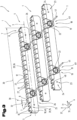
- the exploded view according to Fig.3 shown how an assembly or installation of support rods 1 can be carried out by means of the connecting sections 18. It goes without saying that the support rods 1 do not necessarily have to be exactly identical in order to be connected to one another.
- the support rods 1 can have a different support rod length 30.
- the support rod 1 is widened in the area of the connecting sections 18, i.e. compared to the width of the base body of the support rod 1 wider.
- Such a reinforcement area 49 can be useful for improving the stability of the support bar 1.
- notches 50 can be provided in the vicinity or below the collar 15, so that a good coupling between a cover element 13 and the first coupling area 9 is also possible in the reinforcement area 49.
- a reinforcement region 49 can also be formed on this side and have corresponding notches 50.
- the socket 19 can be coupled to a plug 21 of an identical or similar support rod 1 or can be plugged together in a complementary shape
- the plug 21 can be coupled to a socket 19 of an identical or similar support rod 1 or can be plugged together in a complementary shape
- the plug 21 and socket 19 can have a round cross-section, as shown in the figure. However, other shapes or geometries are also conceivable, for example square cross-sections.
- plug 21 and socket 19 are located directly opposite each other when viewing a support rod 1 orthogonal to the longitudinal axis 3 or when viewed in the installation position in a horizontal plane 6.
- the Fig.2 shows a front view of an embodiment and the Fig.3 a rear side of this embodiment, in which plug 21 and socket 19 are opposite each other. Connections using plug 21 and socket 19 are known in the specialist world.
- the connecting parts can be aligned appropriately by means of a positive locking of the plug parts, can be fixed in a force-locking manner by means of spring force and can also be secured against accidental loosening by screwing.
- connection areas 18 can be formed.
- the figures each show support bars 1 with two identical connection sections 18.
- the support rod 1 is permanently connected to other support rods 1. Permanent can mean that connected support rods 1 can no longer be detached after initial assembly. However, it can also mean that several support rods 1 are made as one piece from a single casting. In all cases, including the detachable connections between several support rods 1 shown, it is It is conceivable that several support rods 1 are pre-assembled to form finished elements so that assembly on site can be carried out efficiently, quickly and modularly. Such finished elements can have a predefined length so that they can be assembled in a modular manner during final assembly on site.
- the connecting section 18 has an opening 22, which opening 22 extends from the further side 14 to the side 20 opposite the further side 14.
- the Fig.1 , 2 and 3 The support bars 1 shown are formed with such openings 22.
- the opening 22 can be a through hole, for example.
- the opening 22 can, as shown in the Fig.3 illustrated, a rod 41, for example a threaded rod, is guided in the horizontal direction 31 and essentially 90° to the longitudinal axis 3 through several connected support rods 1.
- the support rod 1 is made of a plastic material or comprises a plastic material, a connection between the support rods 1 by providing an opening 22 or by providing a metal rod 41 for reinforcing or increasing the load-bearing capacity of the grating 2 can be expedient.
- the support rod 1, as shown in the Fig.2 and 3 shown, has a cross-connection section 23, in which cross-connection section 23 a further opening 24 is formed, which further opening 24 extends from the further side 14 to the side 20 opposite the further side 14.
- the further opening 24 is preferably, like the opening 22 in the connection section 18, orthogonal to the longitudinal axis 3 of the support rod 1 and in the installed position parallel to the horizontal plane 6.
- the further opening 24 in the cross-connection section 23 can serve to simplify a connection of support rods 1 in a corner area of a grating 2 or to improve the stability of a connection in the corner area. This can be done, for example, by means of further rods or threaded rods.
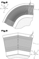
- Fig.9 1 shows such a corner area of a grating 2 in plan view.
- the further opening 24 in the cross-connection section 23 can be provided in the vicinity of the first support bar end 4, but it can also be the case that an additional further opening 24 is formed in a further cross-connection section 23 in the vicinity of the second support bar end 5.
- Fig.2 and 3 Such a bilateral arrangement of cross-connecting sections 23 is shown in each case.
- a corner area of a grating 2 is round, so that the support bars 1 in this round corner area are not connected parallel to each other, but inclined to each other. In this case, it may be necessary for any bar 41 for the cross connection to be flexible so that it can follow the curve in the corner area.
- a round corner area of a grating 2 is shown in plan view.
- a drip element 26, in particular a drip edge or a drip nose is formed on a bottom side 25 of the support rod 1 opposite the top side 8. This is shown by way of example in the Fig.2 and 3 , as well as in the Fig.10 shown.
- the drip element 26 can preferably be designed as a nose with a round or square profile and extend over the entire short side of the underside 25, i.e. when viewed transversely to the longitudinal axis 3.
- Several drip elements 26 can also be provided on the underside 25. It is also conceivable that a groove, notch or groove is formed instead of the nose.
- the drip element 26 is preferably designed on the underside 25 of the support rod 1 in such a way that, in an assembled state, it is positioned above the gutter 42 where the gutter 42 has an inclined gutter wall 43. This can further reduce noise caused by dripping water. However, it is of course also conceivable that the drip element 26 is positioned directly above a horizontal gutter bottom 44 of a gutter 42 in the assembled state.
- the support bars 1 or a grating 2 formed from them can rest on edge areas of a channel 42.
- the support bars 1 are shaped on their front sides or on their two support bar ends 4, 5 in such a way that a distance between the channel wall 43 and the support bar end 4, 5 facing the channel wall 43 is not undesirably large.
- the front sides of the support bars 1 or their support bar ends 4, 5 are not as in the Fig.1 and 2 shown, are flat, but have widenings or extensions in the axial direction.
- a distance in the installed state between the support bar end 4, 5 and the channel wall 43 can be such that the risk of injury from body parts such as fingers getting caught can be kept to a minimum.
- distances of less than or equal to 10 mm, preferably less than or equal to 8 mm, have proven to be useful.
- the Fig. 8 to 12 show conceivable embodiments of gratings 2 comprising interconnected support bars 1.
- the Fig.3 shows a grating 2 made of three supporting bars 1 during assembly, i.e. a process for producing a grating 2.
- the Figures 8 to 12 Overflow gratings or overflow grilles for overflow channels of a swimming pool.
- the grating can have a grid-like or pixel-like appearance due to the shape of the tops 8 of the extensions or the tops 8 of the cover elements 13. This is shown in the Fig. 8 to 12 shown.
- a cover element 13 is placed on the extension 7 and by applying a force 45, a particularly vertical force 45 on the upper side 8 of the cover element 13, for example by manual pressing or by means of a hammer or other suitable tool.
- a template 46 for example in the form of a film, is placed on a grating 2, with a desired arrangement of several individual cover elements 13 being pre-sketched, in particular pre-punched or pre-punched, on this template 46 or film, so that the film has openings 47 at those points where cover elements 13 are subsequently to be applied to the grating 2.
- a template 46 can be placed on the grating 2 and the template 46 can be sprayed over using a marking agent, for example using a paint spray, so that the extensions 7 are marked in the area of the openings 47.
- the template 46 is then removed and cover elements 13 can be attached to the marked extensions 7. This can be particularly useful if complex or large lettering is to be realized with cover elements 13.
- a further variant of a method for attaching instructions to a grating 2 is shown. It is provided that several cover elements 13, especially if these are designed as a cover cap 33 and each to cover an individual extension 7, are applied, for example glued, to a template 46, for example on a film, and thereby form a pattern or lettering, so that a simultaneous application or coupling of several cover elements 13 with the mounted grating 2 is made possible in one operation. In this way, the installation and attachment of instructions can be made possible efficiently and quickly.
- cover elements 13 can be attached with their upper side 8 to a template 46 or film, for example glued on, and already form a lettering or a pattern on the template 46.
- a "negative image” made up of several cover elements 13 can then be placed in one piece on a grating 2 in the coupling step and the individual cover elements 13 can be tapped onto the extensions 7 and brought into engagement with them, for example using a hammer or similar.
- the template 46 or the film can then be pulled off the upper side 8 of the cover elements 13.
- Reference symbol list 1 Support rod 31 horizontal direction 2 Grating 32 distance 3 Longitudinal axis 33 Cover cap 4 first supporting bar end 34 Cover plate 5 second support bar end 35 Long side 6 horizontal plane 36 Long side 7 Extension 37 vertical direction 8th Top of the process 38
- Process longitudinal axis 9 first coupling area 39 further coupling area 10 first coupling surface 40 Underside of a collar 11 second coupling surface 41 pole 12 second coupling area 42 gutter 13 Cover element 43 Gutter wall 14 next page 44 Gutter bottom 15 collar 45 Power 16 Notch 46 template 17 locking lug 47 Breakthrough in the template 18 Connecting section 48 Intermediate area 19 Rifle 49 Gain range 20 Page 50 score 21 Plug 22 breakthrough 23 Cross-connection section 24 further breakthrough 25 Underside of a support rod 26 Drip element 27 Top of the cover element 28 Locking lug of the cover element 29 Locking notch of the cover element 30 Bearing bar length
Landscapes
- Engineering & Computer Science (AREA)
- Architecture (AREA)
- Civil Engineering (AREA)
- Structural Engineering (AREA)
- Water Supply & Treatment (AREA)
- Health & Medical Sciences (AREA)
- Life Sciences & Earth Sciences (AREA)
- Hydrology & Water Resources (AREA)
- Public Health (AREA)
- Sewage (AREA)
Applications Claiming Priority (1)
| Application Number | Priority Date | Filing Date | Title |
|---|---|---|---|
| ATA50781/2022A AT526547B1 (de) | 2022-10-07 | 2022-10-07 | Tragstab und Abdeckelement zur Bildung eines Gitterrostes |
Publications (2)
| Publication Number | Publication Date |
|---|---|
| EP4350104A1 true EP4350104A1 (fr) | 2024-04-10 |
| EP4350104B1 EP4350104B1 (fr) | 2025-08-27 |
Family
ID=88295635
Family Applications (1)
| Application Number | Title | Priority Date | Filing Date |
|---|---|---|---|
| EP23202038.8A Active EP4350104B1 (fr) | 2022-10-07 | 2023-10-06 | Barre de support pour former un caillebotis et caillebotis comprenant une telle barre de support et un élément de couverture |
Country Status (2)
| Country | Link |
|---|---|
| EP (1) | EP4350104B1 (fr) |
| AT (1) | AT526547B1 (fr) |
Cited By (1)
| Publication number | Priority date | Publication date | Assignee | Title |
|---|---|---|---|---|
| EP4647567A1 (fr) * | 2024-05-07 | 2025-11-12 | BWT Pool Products | Caillebotis pour piscine, équipement pour piscine et procédé d'installation |
Citations (5)
| Publication number | Priority date | Publication date | Assignee | Title |
|---|---|---|---|---|
| DE3910126A1 (de) * | 1989-03-29 | 1990-10-04 | Dieter Arens | Rost zur bildung von laufmatten oder fussabstreifern |
| KR100944807B1 (ko) * | 2009-07-28 | 2010-02-26 | 서일공영 주식회사 | 안전형 그레이팅 |
| EP3023560B1 (fr) | 2014-11-19 | 2017-07-12 | Dakota Group S.a.s. di Zeno Cipriani & C. | Element pour la formation de grilles de piscine et grille de piscine comprenand ledit element |
| WO2020115210A1 (fr) * | 2018-12-07 | 2020-06-11 | ACO Severin Ahlmann GmbH & Co Kommanditgesellschaft | Structure porteuse et procédé de fabrication |
| CN213869132U (zh) | 2020-09-21 | 2021-08-03 | 浙江恒动环境科技有限公司 | 一种防止池水进入池岸的溢水格栅及溢水盖板 |
Family Cites Families (4)
| Publication number | Priority date | Publication date | Assignee | Title |
|---|---|---|---|---|
| US1180953A (en) * | 1914-04-01 | 1916-04-25 | John F Steckenreiter | Area-grating. |
| FR2710724B1 (fr) * | 1993-09-27 | 1995-12-01 | Fameca | Grille, en particulier caillebotis, en matière synthétique, notamment composite et procédés et installations pour sa conception. |
| US20080163415A1 (en) * | 2007-01-08 | 2008-07-10 | Lawson Robert B | Pool grating having curves therein |
| DE202007008925U1 (de) * | 2007-06-26 | 2007-09-06 | Zeller, Rene | Längsroste in verschachtelter Ausführung aus Querrosten |
-
2022
- 2022-10-07 AT ATA50781/2022A patent/AT526547B1/de active
-
2023
- 2023-10-06 EP EP23202038.8A patent/EP4350104B1/fr active Active
Patent Citations (5)
| Publication number | Priority date | Publication date | Assignee | Title |
|---|---|---|---|---|
| DE3910126A1 (de) * | 1989-03-29 | 1990-10-04 | Dieter Arens | Rost zur bildung von laufmatten oder fussabstreifern |
| KR100944807B1 (ko) * | 2009-07-28 | 2010-02-26 | 서일공영 주식회사 | 안전형 그레이팅 |
| EP3023560B1 (fr) | 2014-11-19 | 2017-07-12 | Dakota Group S.a.s. di Zeno Cipriani & C. | Element pour la formation de grilles de piscine et grille de piscine comprenand ledit element |
| WO2020115210A1 (fr) * | 2018-12-07 | 2020-06-11 | ACO Severin Ahlmann GmbH & Co Kommanditgesellschaft | Structure porteuse et procédé de fabrication |
| CN213869132U (zh) | 2020-09-21 | 2021-08-03 | 浙江恒动环境科技有限公司 | 一种防止池水进入池岸的溢水格栅及溢水盖板 |
Cited By (1)
| Publication number | Priority date | Publication date | Assignee | Title |
|---|---|---|---|---|
| EP4647567A1 (fr) * | 2024-05-07 | 2025-11-12 | BWT Pool Products | Caillebotis pour piscine, équipement pour piscine et procédé d'installation |
Also Published As
| Publication number | Publication date |
|---|---|
| AT526547A1 (de) | 2024-04-15 |
| AT526547B1 (de) | 2024-05-15 |
| EP4350104B1 (fr) | 2025-08-27 |
Similar Documents
| Publication | Publication Date | Title |
|---|---|---|
| DE2752618A1 (de) | Zusammengefuegte struktur | |
| EP4350104B1 (fr) | Barre de support pour former un caillebotis et caillebotis comprenant une telle barre de support et un élément de couverture | |
| DE102020117657A1 (de) | Verbindungssystem | |
| EP2851485A1 (fr) | Façade | |
| DE2908284C2 (de) | Schaltafel für Betonwände | |
| DE102009037977A1 (de) | Absperrelement, insbesondere ein Bauzaun, eine Absperrschranke oder dgl., Vorrichtung zur Verkettung von Absperrelementen und Schwenkvorrichtung zwischen zwei Absperrelementen | |
| DE102009049160B4 (de) | Vorrichtung zur Befestigung einer Verkehrssicherungseinrichtung in Form eines Leitbakenkörpers oder dergleichen an einer Fußplatte mit Hilfe eines Adapters | |
| DE10250257A1 (de) | Straßenleitpfostenfuß | |
| DE2724398A1 (de) | Verfahren zum herstellen eines fundamentes, insbesondere fuer schornsteine o.ae. bauwerke, z.b. saeulen, masten, tuerme o.dgl. lehrenartige vorrichtung zur durchfuehrung dieses verfahrens sowie in verbindung mit der lehrenartigen vorrichtung bei dem verfahren zu verwendende verankerungsstaebe | |
| WO2003040496A1 (fr) | Dispositif de fixation de sections d'une cloture grillagee a un pieu | |
| DE8705002U1 (de) | Einbauhilfe zum Abschalen eines Betonbauteils in einem Anschlußbereich | |
| DE19903422A1 (de) | Schließblech | |
| DE10013981B4 (de) | Straßenaufsatz | |
| DE202019001472U1 (de) | Werkzeug zum ausgerichteten Montieren von Geräteeinsätzen | |
| EP0311886B1 (fr) | Cadre pour la construction de fermetures de regards de sol | |
| DE19949697B4 (de) | Vorrichtung zum Verschliessen von Rohrenden | |
| DE2060777A1 (de) | Mosaik-Schaltbild | |
| DE2700210B2 (de) | Abdeckelement | |
| DE2540145A1 (de) | Abstandhalter | |
| DE29519905U1 (de) | Gelochtes Folienband für Bauzwecke | |
| DE202009015200U1 (de) | Balkonkonstruktion | |
| DE102004023076A1 (de) | Einrichtung zum Verbinden koaxialer Rohre, insbesondere für Regalsysteme | |
| DE2842172C3 (de) | Schaltafel | |
| DE3408073A1 (de) | Frontsystem fuer in baugruppentraeger einschiebbare steckbaugruppen | |
| DE202015102013U1 (de) | Transporthilfe |
Legal Events
| Date | Code | Title | Description |
|---|---|---|---|
| PUAI | Public reference made under article 153(3) epc to a published international application that has entered the european phase |
Free format text: ORIGINAL CODE: 0009012 |
|
| STAA | Information on the status of an ep patent application or granted ep patent |
Free format text: STATUS: THE APPLICATION HAS BEEN PUBLISHED |
|
| AK | Designated contracting states |
Kind code of ref document: A1 Designated state(s): AL AT BE BG CH CY CZ DE DK EE ES FI FR GB GR HR HU IE IS IT LI LT LU LV MC ME MK MT NL NO PL PT RO RS SE SI SK SM TR |
|
| STAA | Information on the status of an ep patent application or granted ep patent |
Free format text: STATUS: REQUEST FOR EXAMINATION WAS MADE |
|
| 17P | Request for examination filed |
Effective date: 20240925 |
|
| RBV | Designated contracting states (corrected) |
Designated state(s): AL AT BE BG CH CY CZ DE DK EE ES FI FR GB GR HR HU IE IS IT LI LT LU LV MC ME MK MT NL NO PL PT RO RS SE SI SK SM TR |
|
| STAA | Information on the status of an ep patent application or granted ep patent |
Free format text: STATUS: EXAMINATION IS IN PROGRESS |
|
| GRAP | Despatch of communication of intention to grant a patent |
Free format text: ORIGINAL CODE: EPIDOSNIGR1 |
|
| STAA | Information on the status of an ep patent application or granted ep patent |
Free format text: STATUS: GRANT OF PATENT IS INTENDED |
|
| 17Q | First examination report despatched |
Effective date: 20250304 |
|
| RIC1 | Information provided on ipc code assigned before grant |
Ipc: E04H 4/06 20060101ALI20250228BHEP Ipc: E04H 4/12 20060101AFI20250228BHEP |
|
| INTG | Intention to grant announced |
Effective date: 20250320 |
|
| GRAS | Grant fee paid |
Free format text: ORIGINAL CODE: EPIDOSNIGR3 |
|
| GRAA | (expected) grant |
Free format text: ORIGINAL CODE: 0009210 |
|
| STAA | Information on the status of an ep patent application or granted ep patent |
Free format text: STATUS: THE PATENT HAS BEEN GRANTED |
|
| AK | Designated contracting states |
Kind code of ref document: B1 Designated state(s): AL AT BE BG CH CY CZ DE DK EE ES FI FR GB GR HR HU IE IS IT LI LT LU LV MC ME MK MT NL NO PL PT RO RS SE SI SK SM TR |
|
| REG | Reference to a national code |
Ref country code: CH Ref legal event code: EP |
|
| REG | Reference to a national code |
Ref country code: DE Ref legal event code: R096 Ref document number: 502023001671 Country of ref document: DE |
|
| REG | Reference to a national code |
Ref country code: IE Ref legal event code: FG4D Free format text: LANGUAGE OF EP DOCUMENT: GERMAN |
|
| REG | Reference to a national code |
Ref country code: NL Ref legal event code: MP Effective date: 20250827 |
|
| PG25 | Lapsed in a contracting state [announced via postgrant information from national office to epo] |
Ref country code: IS Free format text: LAPSE BECAUSE OF FAILURE TO SUBMIT A TRANSLATION OF THE DESCRIPTION OR TO PAY THE FEE WITHIN THE PRESCRIBED TIME-LIMIT Effective date: 20251227 |
|
| PG25 | Lapsed in a contracting state [announced via postgrant information from national office to epo] |
Ref country code: NO Free format text: LAPSE BECAUSE OF FAILURE TO SUBMIT A TRANSLATION OF THE DESCRIPTION OR TO PAY THE FEE WITHIN THE PRESCRIBED TIME-LIMIT Effective date: 20251127 |
|
| REG | Reference to a national code |
Ref country code: LT Ref legal event code: MG9D |
|
| PG25 | Lapsed in a contracting state [announced via postgrant information from national office to epo] |
Ref country code: PT Free format text: LAPSE BECAUSE OF FAILURE TO SUBMIT A TRANSLATION OF THE DESCRIPTION OR TO PAY THE FEE WITHIN THE PRESCRIBED TIME-LIMIT Effective date: 20251229 |
|
| PGFP | Annual fee paid to national office [announced via postgrant information from national office to epo] |
Ref country code: AT Payment date: 20260113 Year of fee payment: 3 |
|
| PG25 | Lapsed in a contracting state [announced via postgrant information from national office to epo] |
Ref country code: FI Free format text: LAPSE BECAUSE OF FAILURE TO SUBMIT A TRANSLATION OF THE DESCRIPTION OR TO PAY THE FEE WITHIN THE PRESCRIBED TIME-LIMIT Effective date: 20250827 |
|
| PG25 | Lapsed in a contracting state [announced via postgrant information from national office to epo] |
Ref country code: HR Free format text: LAPSE BECAUSE OF FAILURE TO SUBMIT A TRANSLATION OF THE DESCRIPTION OR TO PAY THE FEE WITHIN THE PRESCRIBED TIME-LIMIT Effective date: 20250827 Ref country code: NL Free format text: LAPSE BECAUSE OF FAILURE TO SUBMIT A TRANSLATION OF THE DESCRIPTION OR TO PAY THE FEE WITHIN THE PRESCRIBED TIME-LIMIT Effective date: 20250827 |
|
| PG25 | Lapsed in a contracting state [announced via postgrant information from national office to epo] |
Ref country code: GR Free format text: LAPSE BECAUSE OF FAILURE TO SUBMIT A TRANSLATION OF THE DESCRIPTION OR TO PAY THE FEE WITHIN THE PRESCRIBED TIME-LIMIT Effective date: 20251128 |
|
| PG25 | Lapsed in a contracting state [announced via postgrant information from national office to epo] |
Ref country code: SE Free format text: LAPSE BECAUSE OF FAILURE TO SUBMIT A TRANSLATION OF THE DESCRIPTION OR TO PAY THE FEE WITHIN THE PRESCRIBED TIME-LIMIT Effective date: 20250827 |
|
| PGFP | Annual fee paid to national office [announced via postgrant information from national office to epo] |
Ref country code: CZ Payment date: 20251002 Year of fee payment: 3 |
|
| PG25 | Lapsed in a contracting state [announced via postgrant information from national office to epo] |
Ref country code: LV Free format text: LAPSE BECAUSE OF FAILURE TO SUBMIT A TRANSLATION OF THE DESCRIPTION OR TO PAY THE FEE WITHIN THE PRESCRIBED TIME-LIMIT Effective date: 20250827 |
|
| PG25 | Lapsed in a contracting state [announced via postgrant information from national office to epo] |
Ref country code: PL Free format text: LAPSE BECAUSE OF FAILURE TO SUBMIT A TRANSLATION OF THE DESCRIPTION OR TO PAY THE FEE WITHIN THE PRESCRIBED TIME-LIMIT Effective date: 20250827 Ref country code: BG Free format text: LAPSE BECAUSE OF FAILURE TO SUBMIT A TRANSLATION OF THE DESCRIPTION OR TO PAY THE FEE WITHIN THE PRESCRIBED TIME-LIMIT Effective date: 20250827 |
|
| PG25 | Lapsed in a contracting state [announced via postgrant information from national office to epo] |
Ref country code: RS Free format text: LAPSE BECAUSE OF FAILURE TO SUBMIT A TRANSLATION OF THE DESCRIPTION OR TO PAY THE FEE WITHIN THE PRESCRIBED TIME-LIMIT Effective date: 20251127 |
|
| PG25 | Lapsed in a contracting state [announced via postgrant information from national office to epo] |
Ref country code: ES Free format text: LAPSE BECAUSE OF FAILURE TO SUBMIT A TRANSLATION OF THE DESCRIPTION OR TO PAY THE FEE WITHIN THE PRESCRIBED TIME-LIMIT Effective date: 20250827 |
|
| PG25 | Lapsed in a contracting state [announced via postgrant information from national office to epo] |
Ref country code: RO Free format text: LAPSE BECAUSE OF FAILURE TO SUBMIT A TRANSLATION OF THE DESCRIPTION OR TO PAY THE FEE WITHIN THE PRESCRIBED TIME-LIMIT Effective date: 20250827 |
|
| PG25 | Lapsed in a contracting state [announced via postgrant information from national office to epo] |
Ref country code: SM Free format text: LAPSE BECAUSE OF FAILURE TO SUBMIT A TRANSLATION OF THE DESCRIPTION OR TO PAY THE FEE WITHIN THE PRESCRIBED TIME-LIMIT Effective date: 20250827 |
|
| PG25 | Lapsed in a contracting state [announced via postgrant information from national office to epo] |
Ref country code: DK Free format text: LAPSE BECAUSE OF FAILURE TO SUBMIT A TRANSLATION OF THE DESCRIPTION OR TO PAY THE FEE WITHIN THE PRESCRIBED TIME-LIMIT Effective date: 20250827 |
|
| PG25 | Lapsed in a contracting state [announced via postgrant information from national office to epo] |
Ref country code: IT Free format text: LAPSE BECAUSE OF FAILURE TO SUBMIT A TRANSLATION OF THE DESCRIPTION OR TO PAY THE FEE WITHIN THE PRESCRIBED TIME-LIMIT Effective date: 20250827 |
|
| PG25 | Lapsed in a contracting state [announced via postgrant information from national office to epo] |
Ref country code: SK Free format text: LAPSE BECAUSE OF FAILURE TO SUBMIT A TRANSLATION OF THE DESCRIPTION OR TO PAY THE FEE WITHIN THE PRESCRIBED TIME-LIMIT Effective date: 20250827 Ref country code: EE Free format text: LAPSE BECAUSE OF FAILURE TO SUBMIT A TRANSLATION OF THE DESCRIPTION OR TO PAY THE FEE WITHIN THE PRESCRIBED TIME-LIMIT Effective date: 20250827 |