EP4350131A1 - Mécanisme d'élévation de température destiné à un dispositif de traitement de gaz par soufflage et moteur doté de celui-ci - Google Patents
Mécanisme d'élévation de température destiné à un dispositif de traitement de gaz par soufflage et moteur doté de celui-ci Download PDFInfo
- Publication number
- EP4350131A1 EP4350131A1 EP22815579.2A EP22815579A EP4350131A1 EP 4350131 A1 EP4350131 A1 EP 4350131A1 EP 22815579 A EP22815579 A EP 22815579A EP 4350131 A1 EP4350131 A1 EP 4350131A1
- Authority
- EP
- European Patent Office
- Prior art keywords
- blow
- gas
- treatment device
- head cover
- heat
- Prior art date
- Legal status (The legal status is an assumption and is not a legal conclusion. Google has not performed a legal analysis and makes no representation as to the accuracy of the status listed.)
- Granted
Links
Images



Classifications
-
- F—MECHANICAL ENGINEERING; LIGHTING; HEATING; WEAPONS; BLASTING
- F01—MACHINES OR ENGINES IN GENERAL; ENGINE PLANTS IN GENERAL; STEAM ENGINES
- F01M—LUBRICATING OF MACHINES OR ENGINES IN GENERAL; LUBRICATING INTERNAL COMBUSTION ENGINES; CRANKCASE VENTILATING
- F01M13/00—Crankcase ventilating or breathing
- F01M13/04—Crankcase ventilating or breathing having means for purifying air before leaving crankcase, e.g. removing oil
-
- F—MECHANICAL ENGINEERING; LIGHTING; HEATING; WEAPONS; BLASTING
- F01—MACHINES OR ENGINES IN GENERAL; ENGINE PLANTS IN GENERAL; STEAM ENGINES
- F01M—LUBRICATING OF MACHINES OR ENGINES IN GENERAL; LUBRICATING INTERNAL COMBUSTION ENGINES; CRANKCASE VENTILATING
- F01M13/00—Crankcase ventilating or breathing
- F01M13/04—Crankcase ventilating or breathing having means for purifying air before leaving crankcase, e.g. removing oil
- F01M13/0416—Crankcase ventilating or breathing having means for purifying air before leaving crankcase, e.g. removing oil arranged in valve-covers
-
- F—MECHANICAL ENGINEERING; LIGHTING; HEATING; WEAPONS; BLASTING
- F01—MACHINES OR ENGINES IN GENERAL; ENGINE PLANTS IN GENERAL; STEAM ENGINES
- F01M—LUBRICATING OF MACHINES OR ENGINES IN GENERAL; LUBRICATING INTERNAL COMBUSTION ENGINES; CRANKCASE VENTILATING
- F01M11/00—Component parts, details or accessories, not provided for in, or of interest apart from, groups F01M1/00 - F01M9/00
- F01M11/02—Arrangements of lubricant conduits
-
- F—MECHANICAL ENGINEERING; LIGHTING; HEATING; WEAPONS; BLASTING
- F01—MACHINES OR ENGINES IN GENERAL; ENGINE PLANTS IN GENERAL; STEAM ENGINES
- F01M—LUBRICATING OF MACHINES OR ENGINES IN GENERAL; LUBRICATING INTERNAL COMBUSTION ENGINES; CRANKCASE VENTILATING
- F01M13/00—Crankcase ventilating or breathing
-
- F—MECHANICAL ENGINEERING; LIGHTING; HEATING; WEAPONS; BLASTING
- F01—MACHINES OR ENGINES IN GENERAL; ENGINE PLANTS IN GENERAL; STEAM ENGINES
- F01M—LUBRICATING OF MACHINES OR ENGINES IN GENERAL; LUBRICATING INTERNAL COMBUSTION ENGINES; CRANKCASE VENTILATING
- F01M13/00—Crankcase ventilating or breathing
- F01M13/02—Crankcase ventilating or breathing by means of additional source of positive or negative pressure
-
- F—MECHANICAL ENGINEERING; LIGHTING; HEATING; WEAPONS; BLASTING
- F01—MACHINES OR ENGINES IN GENERAL; ENGINE PLANTS IN GENERAL; STEAM ENGINES
- F01M—LUBRICATING OF MACHINES OR ENGINES IN GENERAL; LUBRICATING INTERNAL COMBUSTION ENGINES; CRANKCASE VENTILATING
- F01M5/00—Heating, cooling, or controlling temperature of lubricant; Lubrication means facilitating engine starting
- F01M5/001—Heating
-
- F—MECHANICAL ENGINEERING; LIGHTING; HEATING; WEAPONS; BLASTING
- F01—MACHINES OR ENGINES IN GENERAL; ENGINE PLANTS IN GENERAL; STEAM ENGINES
- F01M—LUBRICATING OF MACHINES OR ENGINES IN GENERAL; LUBRICATING INTERNAL COMBUSTION ENGINES; CRANKCASE VENTILATING
- F01M13/00—Crankcase ventilating or breathing
- F01M13/04—Crankcase ventilating or breathing having means for purifying air before leaving crankcase, e.g. removing oil
- F01M2013/0438—Crankcase ventilating or breathing having means for purifying air before leaving crankcase, e.g. removing oil with a filter
-
- F—MECHANICAL ENGINEERING; LIGHTING; HEATING; WEAPONS; BLASTING
- F01—MACHINES OR ENGINES IN GENERAL; ENGINE PLANTS IN GENERAL; STEAM ENGINES
- F01M—LUBRICATING OF MACHINES OR ENGINES IN GENERAL; LUBRICATING INTERNAL COMBUSTION ENGINES; CRANKCASE VENTILATING
- F01M13/00—Crankcase ventilating or breathing
- F01M13/04—Crankcase ventilating or breathing having means for purifying air before leaving crankcase, e.g. removing oil
- F01M2013/0455—Crankcase ventilating or breathing having means for purifying air before leaving crankcase, e.g. removing oil with a de-icing or defrosting system
-
- F—MECHANICAL ENGINEERING; LIGHTING; HEATING; WEAPONS; BLASTING
- F01—MACHINES OR ENGINES IN GENERAL; ENGINE PLANTS IN GENERAL; STEAM ENGINES
- F01M—LUBRICATING OF MACHINES OR ENGINES IN GENERAL; LUBRICATING INTERNAL COMBUSTION ENGINES; CRANKCASE VENTILATING
- F01M13/00—Crankcase ventilating or breathing
- F01M13/04—Crankcase ventilating or breathing having means for purifying air before leaving crankcase, e.g. removing oil
- F01M2013/0472—Crankcase ventilating or breathing having means for purifying air before leaving crankcase, e.g. removing oil using heating means
-
- F—MECHANICAL ENGINEERING; LIGHTING; HEATING; WEAPONS; BLASTING
- F02—COMBUSTION ENGINES; HOT-GAS OR COMBUSTION-PRODUCT ENGINE PLANTS
- F02F—CYLINDERS, PISTONS OR CASINGS, FOR COMBUSTION ENGINES; ARRANGEMENTS OF SEALINGS IN COMBUSTION ENGINES
- F02F7/00—Casings, e.g. crankcases
- F02F7/006—Camshaft or pushrod housings
-
- Y—GENERAL TAGGING OF NEW TECHNOLOGICAL DEVELOPMENTS; GENERAL TAGGING OF CROSS-SECTIONAL TECHNOLOGIES SPANNING OVER SEVERAL SECTIONS OF THE IPC; TECHNICAL SUBJECTS COVERED BY FORMER USPC CROSS-REFERENCE ART COLLECTIONS [XRACs] AND DIGESTS
- Y02—TECHNOLOGIES OR APPLICATIONS FOR MITIGATION OR ADAPTATION AGAINST CLIMATE CHANGE
- Y02T—CLIMATE CHANGE MITIGATION TECHNOLOGIES RELATED TO TRANSPORTATION
- Y02T10/00—Road transport of goods or passengers
- Y02T10/10—Internal combustion engine [ICE] based vehicles
- Y02T10/12—Improving ICE efficiencies
Definitions
- the present invention relates to a temperature raising mechanism for a blow-by gas treatment device which is mounted on an internal combustion engine such as a diesel engine and separates the blow-by gas into oil and gas and an engine provided with the temperature raising mechanism for the blow-by gas treatment device.
- a blow-by gas filter In a head cover of the diesel engine, for example, a blow-by gas filter is incorporated.
- the blow-by gas filter separates the blow-by gas into oil and gas such as a combusted gas.
- the oil separated from the blow-by gas contains moisture (steam).
- the PTL 1 discloses a blow-by gas recirculating device.
- the blow-by gas recirculating device described in the PTL 1 has an oil separator which captures and removes the oil from the blow-by gas mounted inside the head cover.
- the oil separator has a filter portion with an impactor structure.
- the filter portion with the impactor structure includes a speed-increasing mechanism which increases a speed of the blow-by gas and a wall surface against which the blow-by gas whose speed was increased is caused to collide.
- the moisture contained in the oil might freeze at a low temperature in the speed-increasing mechanism of the filter portion, for example. If the moisture contained in the oil freezes in the amplification mechanism of the filter portion, for example, an internal pressure in a crank case rises, and there is a concern that an optional seal portion is broken. In this point, the blow-by gas recirculating device described in the PTL 1 has a room for improvement.
- the present invention was made in view of the circumstances described above and has an object to provide a temperature raising mechanism for a blow-by gas treatment device which can suppress freezing of moisture contained in blow-by gas at a low temperature and an engine provided with a temperature raising mechanism for a blow-by gas treatment device.
- the temperature raising mechanism for a blow-by gas treatment device which treats blow-by gas generated in an engine
- a temperature raising mechanism for a blow-by gas treatment device according to the present invention including a head cover mounted on a cylinder head of the engine, a blow-by gas treatment device which is disposed in the head cover and treats the blow-by gas, and heating means which is fixed to an outer surface of the head cover and generates heat
- the blow-by gas treatment device has a partition wall part which is fixed to the head cover and partitions the inside of the head cover into a plurality of regions and a separating portion which is provided on the partition wall part and separates the blow-by gas into oil and gas
- the head cover has a heat conducting portion which is in contact with the partition wall part and conducts heat generated by the heating means to the separating portion.
- the heating means which generates heat is fixed to the outer surface of the head cover.
- the blow-by gas treatment device which treats the blow-by gas generated in the engine is disposed inside the head cover.
- the blow-by gas treatment device has the partition wall part and the separating portion.
- the partition wall part is fixed to the head cover and partitions the inside of the head cover into a plurality of regions.
- the separating portion is provided on the partition wall part and separates the blow-by gas into oil and gas.
- the head cover has the heat conducting portion.
- the heat conducting portion is in contact with the partition wall part and conducts the heat generated by the heating means to the separating portion.
- the temperature raising mechanism for the blow-by gas treatment device can suppress freezing of moisture contained in the blow-by gas at a low temperature in the separating portion.
- the heat generated by the heating means is not directly conducted to the separating portion but is conducted to the separating portion via the heat conducting portion of the head cover in contact with the partition wall part of the blow-by gas treatment device.
- the temperature raising mechanism for the blow-by gas treatment device can suppress freezing of the moisture contained in the blow-by gas at a low temperature in the separating portion, while the separating portion is suppressed from becoming a high temperature, and carbonization of oil contained in the blow-by gas is suppressed.
- the partition wall part is characterized by having a heat-conduction assisting portion which is in contact with the heat conducting portion, receives the heat generated by the heating means and conducts it to the separating portion, and the outer surface is inclined with respect to an upper surface of the heat-conduction assisting portion.
- the partition wall part has the heat-conduction assisting portion.
- the heat-conduction assisting portion is in contact with the heat conducting portion, receives the heat generated by the heating means and conducts it to the separating portion.
- the outer surface of the head cover to which the heating means is fixed is inclined with respect to the upper surface of the heat-conduction assisting portion.
- the temperature raising mechanism for the blow-by gas treatment device can efficiently conduct the heat generated by the heating means to the separating portion via the heat conducting portion of the head cover and the heat-conduction assisting portion of the partition wall part, and freezing of the moisture contained in the blow-by gas at a low temperature in the separating portion can be further suppressed.
- the partition wall part is characterized by having a heat-conduction assisting portion which is in contact with the heat conducting portion, receives heat generated by the heating means and conducts it to the separating portion, and the outer surface is perpendicular to the upper surface of the heat-conduction assisting portion.
- the partition wall part has the heat-conduction assisting portion.
- the heat-conduction assisting portion is in contact with the heat conducting portion and receives the heat generated by the heating means and conducts it to the separating portion.
- the outer surface of the head cover to which the heating means is fixed is perpendicular to the upper surface of the heat-conduction assisting portion.
- the temperature raising mechanism for the blow-by gas treatment device can efficiently conduct the heat generated by the heating means to the separating portion via the heat conducting portion of the head cover and the heat-conduction assisting portion of the partition wall part, while complication of a disposition structure of the heating means is suppressed.
- the heating means is characterized by being a heater having a positive temperature characteristic using a semiconductor ceramic with barium titanate as a main component.
- the heating means is a heater having a positive temperature characteristic using a semiconductor ceramic with barium titanate as a main component.
- a resistance value that rapidly increases at a certain temperature when a temperature rises, can be set to the heating means.
- the heating means a large amount of an electric current flows at a low temperature so as to increase a heat generation amount, and as the heat is generated, the resistance value increases, the electric current is limited, and the heat generation amount can be suppressed.
- the temperature raising mechanism for the blow-by gas treatment device can suppress that the separating portion becomes a high temperature, the oil contained in the blow-by gas is carbonized, and the moisture contained in the blow-by gas freezes at a low temperature in the separating portion.
- the thickness of the part in the heat conducting portion in contact with the partition wall part is characterized by being larger than the thickness of the other parts in the heat conducting portion not in contact with the partition wall part.
- the thickness of the part in the heat conducting portion in contact with the partition wall part is larger than the thickness of the other parts in the heat conducting portion not in contact with the partition wall part.
- the heat generated by the heating means can be easily conducted to the part in contact with the partition wall part as compared with the other parts of the head cover.
- a heat capacity of the part in contact with the partition wall part can be increased.
- the temperature raising mechanism for the blow-by gas treatment device according to the present invention can efficiently conduct the heat generated by the heating means to the separating portion and further suppress the freezing of the moisture contained in the blow-by gas at a low temperature in the separating portion.
- the separating portion is characterized by being provided with inclination in a direction in which the oil separated from the blow-by gas by the separating portion is led to an oil guiding portion.
- the temperature raising mechanism for the blow-by gas treatment device since the separating portion is inclined in the direction in which the oil separated from the blow-by gas by the separating portion is led to the oil guiding portion, the oil separated from the blow-by gas can be reliably led to the oil guiding portion. As a result, the temperature raising mechanism for the blow-by gas treatment device according to the present invention can suppress the oil from staying in the separating portion and the freezing of the moisture contained in the oil of the blow-by gas at a low temperature in the separating portion.
- the separating portion is characterized by having a flow-velocity raising operation portion which raises a flow velocity of the blow-by gas along a direction inclined with respect to a vertical direction, a filter through which the blow-by gas whose flow velocity is raised by the flow-velocity raising operation portion is passed, and a collision plate against which the blow-by gas having passed through the filter is caused to collide and to be separated into the oil and the gas, in which a surface of the flow-velocity raising operation portion opposed to the collision plate is inclined downward toward the oil guiding portion.
- the flow-velocity raising operation portion causes the blow-by gas to collide against the collision plate, while raising the flow velocity of the blow-by gas along the direction inclined with respect to the vertical direction (up-down direction).
- the blow-by gas is reliably separated into oil and gas.
- the oil separated from the blow-by gas on the collision plate passes through the filter and drops onto the surface of the flow-velocity raising operation portion opposed to the collision plate.
- the surface of the flow-velocity raising operation portion is inclined downward toward the oil guiding portion.
- the temperature raising mechanism for the blow-by gas treatment device can suppress the oil from staying in the separating portion and suppress the freezing of the moisture contained in the oil of the blow-by gas at a low temperature in the separating portion.
- an engine including the temperature raising mechanism for the blow-by gas treatment device which treats the blow-by gas generated in the engine, in which the temperature raising mechanism for the blow-by gas treatment device has a head cover assembled to a cylinder head of the engine, the blow-by gas treatment device which is disposed in the head cover and treats the blow-by gas, and heating means which is fixed to an outer surface of the head cover and generates heat, characterized in that the blow-by gas treatment device has a partition wall part which is fixed to the head cover and partitions an inside of the head cover into a plurality of regions and a separating portion which is provided in the partition wall part and separates the blow-by gas into oil and gas, and the head cover has a heat conducting portion which is in contact with the partition wall part and conducts the heat generated by the heating means to the separating portion.
- the heating means of the temperature raising mechanism for the blow-by gas treatment device is fixed to the outer surface of the head cover and generates heat.
- the blow-by gas treatment device which treats the blow-by gas generated in the engine is disposed inside the head cover.
- the blow-by gas treatment device has the partition wall part and the separating portion.
- the partition wall part is fixed to the head cover and partitions the inside of the head cover into a plurality of regions.
- the separating portion is provided in the partition wall part and separates the blow-by gas into oil and gas.
- the head cover has a heat conducting portion. The head conducting portion is in contact with the partition wall part and conducts the heat generated by the heating means to the separating portion.
- the temperature raising mechanism for the blow-by gas treatment device can suppress freezing of moisture contained in the blow-by gas at a low temperature in the separating portion.
- the heat generated by the heating means is not directly conducted to the separating portion but is conducted to the separating portion via the heat conducting portion of the head cover in contact with the partition wall part of the blow-by gas treatment device.
- the temperature raising mechanism for the blow-by gas treatment device can suppress that the separating portion becomes a high temperature, that the oil contained in the blow-by gas is carbonized, and that the moisture contained in the blow-by gas is frozen at a low temperature in the separating portion.
- the temperature raising mechanism for the blow-by gas treatment device which can suppress freezing of moisture contained in the blow-by gas at a low temperature and an engine including the temperature raising mechanism for the blow-by gas treatment device can be provided.
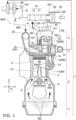
- An engine 1 shown in Fig. 1 is an internal combustion engine and is an industrial diesel engine, for example.
- the engine 1 is a multi-cylinder engine such as a supercharging-type high-output 3-cylinder or 4-cylinder engine with a turbocharger, for example.
- the engine 1 is mounted on a vehicle or the like such as a construction machine, an agricultural machine, and a lawnmower.
- the engine 1 includes a cylinder block 2, a cylinder head 3, a head cover 4, an oil pun 7, and a blow-by gas treatment device 100.
- the cylinder head 3 is assembled onto the cylinder block 2.
- the head cover 4 made of aluminum is assembled onto the cylinder head 3.
- the cylinder block 2 has a cylinder 5 on an upper part and a crank case 6 on a lower part.
- the oil pun 7 is disposed on a lower part of the crank case 6.
- a piston 8 is disposed in the cylinder 5.
- a crank shaft 9 is disposed in the crank case 6.
- the piston 8 is connected to the crank shaft 9 via a con rod 10.
- the engine 1 includes a temperature raising mechanism 800 for the blow-by gas treatment device.
- the temperature raising mechanism 800 for the blow-by gas treatment device has the head cover 4, the blow-by gas treatment device 100, and heating means 600.
- the heating means 600 is fixed to an outer surface of the head cover 4. Details of the temperature raising mechanism 800 for the blow-by gas treatment device will be described later.
- the cylinder 5 has a valve cam chamber 11.
- the valve cam chamber 11 accommodates a valve cam shaft 12.
- a tappet 13 is capable of vertical movement along a tappet guide hole 14.
- a lower part of the tappet 13 is mounted on the valve cam shaft 12.
- a push rod 15 passes through an insertion hole 16.
- a rocker arm 17 is disposed in the head cover 4. An upper end part of the push rod 15 is in contact with the rocker arm 17.
- the rocker arm 17 is urged to the upper end part side of the push rod 15 by a spring 18.
- An intake valve 19 and an exhaust valve 20 are vertically moved by power transmitted via the push rod 15 and the rocker arm 17 by means of rotation of the valve cam shaft 12 and opens/closes each of an intake port and an exhaust port.
- an oil flow-out hole 21, for example, is provided in the tappet 13.
- An oil drop hole 22 is provided from the valve cam chamber 11 to the crank case 6.
- the oil return path 99 can return the oil in the head cover 4 to the oil pun 7 through the inside of the crank case 6.
- Each cylinder of the cylinder head 3 is connected to an intake passage 30 and an exhaust passage 31.
- blow-by gas BG is generated in some cases.
- the blow-by gas BG is gas flowing into the crank case 6 through a gap between the piston 8 and the cylinder 5 and contains an uncombusted fuel component or a combusted gas component and a mist such as oil.
- the blow-by gas BG which leaks out of the gap between the cylinder 5 and the piston 8 to the crank case 6 rises into the head cover 4 through the oil return path 99 described above, for example.
- blow-by gas BG leaks out of the gap between the cylinder 5 and the piston 8 to the crank case 6, it intrudes into the head cover 4 through the oil drop hole 22, the valve cam chamber 11, the oil flow-out hole 21 of the tappet 13, and the insertion hole 16 of the oil return path 99 as a blow-by gas passing path, for example.
- the blow-by gas treatment device 100 is provided in the head cover 4.
- the blow-by gas treatment device 100 has a role of separating the blow-by gas BG into oil OL (see Fig. 2 ) and gas (gas after the treatment) G (see Fig. 2 ) obtained by separating a mist of the oil OL.
- the gas G contained in the blow-by gas BG for example, is sent to a piping 41 connected to an intake system outside the head cover 4 via the blow-by gas treatment device 100.
- the gas G contained in the blow-by gas BG is an uncombusted gas component excluding the oil OL and the mist of the oil OL from the blow-by gas BG and a combusted gas component, for example.
- the oil (lubricant component) OL is collected by the oil pun 7 through the head cover 4, the inside of the cylinder head 3, and the oil return path 99, for example.
- a connecting pipe 50T and the piping 41 of an intake piping 50 are connected to each other by a blow-by gas mixed joint 70.
- new intake AR is sucked into the intake piping 50, it passes through an air cleaner 52 and the connecting pipe 50T and enters a main piping 71 of the blow-by gas mixed joint 70.
- the gas G after the oil OL is separated from the blow-by gas BG by the blow-by gas treatment device 100 passes from an outlet portion 40 of the blow-by gas treatment device 100 through the piping 41 and enters a sub piping 72 of the blow-by gas mixed joint 70.
- the new intake AR and the gas G are mixed in the blow-by gas mixed joint 70 and become an intake air B.
- the exhaust air from the exhaust passage 31 is supplied to a turbine 62 of a turbocharger 60, whereby the turbine 62 and a blower 61 are rotated at a high speed.
- the mixed intake air B is supplied to the blower 61 of the turbocharger 60 and is compressed.
- the compressed intake air C is supercharged to the intake passage 30 of the intake system.
- an X-direction shown in Fig. 1 and Fig. 2 is a front-back direction of the engine 1 shown in Fig. 1 , that is, an axial direction of the crank shaft 9.
- a Y-direction is a left-right direction of the engine 1.
- a Z-direction is an up-down direction (vertical direction) of the engine 1.
- the X, Y, Z directions are orthogonal to one another.
- the blow-by gas treatment device 100 is also referred to as a breather device or a breather and is disposed in the head cover 4. As shown in Fig. 2 , the blow-by gas treatment device 100 can separate the blow-by gas BG into the oil OL and the gas G and guide the oil OL and the gas G by separate paths.
- the blow-by gas treatment device 100 has a main structure portion 101 and the outlet portion 40.
- the main structure portion 101 is provided in the head cover 4.
- the main structure portion 101 has a separating portion 330.
- the outlet portion 40 is provided by protruding above the head cover 4.
- the outlet portion 40 is disposed at a substantially center position CP, for example, with respect to the front-back direction, which is the X-direction of the main structure portion 101.
- the outlet portion 40 adjusts a pressure of the gas G which is to be supplied to the intake system of the engine 1 at the substantially center position CP, for example, of the engine 1 and sends only the gas G led from the main structure portion 101 to the piping 41 of the intake system of the engine 1.
- a pressure regulating valve (diaphragm), for example, is provided at the outlet portion 40.
- the pressure regulating valve provided at the outlet portion 40 suppresses inflow of the new intake AR into the engine 1 through the blow-by gas mixed joint 70 and the piping 41 of the intake system shown in Fig. 1 .
- the head cover 4 has an upper surface part 4A, a front surface part 4B, a rear surface part 4C, and left and right surface parts 4D.
- the main structure portion 101 is disposed in a space surrounded by the upper surface part 4A, the front surface part 4B, the rear surface part 4C, and the left and right surface parts 4D.
- the main structure portion 101 takes in and guides the blow-by gas BG and separates the oil OL and the gas G contained in the blow-by gas BG from the blow-by gas BG.
- the main structure portion 101 guides the oil OL and the gas G by separate paths so that the oil OL and the gas G separated from the blow-by gas BG do not leak to an outside of the engine 1.
- the head cover 4 is held by the cylinder head 3 in a state where the inside of the head cover 4 is held airtightly with respect to the outside of the head cover 4. As a result, leaking-out of the blow-by gas BG and the oil OL as well as the gas G separated from the blow-by gas BG to the outside of the engine 1 is suppressed.
- the main structure portion 101 substantially has a first blow-by gas taking-in portion 111, a second blow-by gas taking-in portion 112, the separating portion 330, a first oil guide-groove portion 151, a second oil guide-groove portion 152, a first oil drain 161, and a second oil drain 162.
- Each of the first oil guide-groove portion 151 and the second oil guide-groove portion 152 is an example of the "oil guiding portion" of the present invention.
- the main structure portion 101 has a partition wall part 200, a guide wall part 203, and a guide plate 295 in order to constitute the aforementioned constituent elements.
- the partition wall part 200 is disposed on an X-Y plane in the head cover 4, that is, horizontally, and partitions a lower region 4P and upper regions 4Q, 4R of the head cover 4. Therefore, the lower region 4P and the upper regions 4Q, 4R are spaces independent from each other.
- the partition wall part 200 partitions the inside of the head cover 4 into a plurality of regions.
- the guide wall part 203 reliably guides only the gas G after the treatment to the outlet portion 40.
- the guide wall part 203 is disposed between the partition wall part 200 and the upper surface part 4A of the head cover 4 and partitions the upper region 4Q and the upper region 4R.
- the first blow-by gas taking-in portion 111 and the second blow-by gas taking-in portion 112 are holes formed by the partition wall part 200 and the guide plate 295 and take in the blow-by gas BG.
- the partition wall part 200 is divided into a first guide lower-surface part 231 side and a second guide lower-surface part 232 side with the separating portion 330 at a center.
- the first blow-by gas taking-in portion 111 is provided at a position closer to the front surface part 4B (that is, on a front side of the engine 1) and takes in the blow-by gas BG from the front side.
- the second blow-by gas taking-in portion 112 is provided at a position closer to the rear surface part 4C (that is, on a rear side of the engine 1) and takes in the blow-by gas BG from the rear side.
- blow-by gas BG when the blow-by gas BG having risen in the crank case 6 reaches the lower region 4P of the head cover 4 shown in Fig. 2 , it passes through the first blow-by gas taking-in portion 111 and is taken in between the first guide lower-surface part 231 and the guide plate 295 of the partition wall part 200 and is guided toward the separating portion 330.
- the blow-by gas BG passes through the second blow-by gas taking-in portion 112 and is taken in between the second guide lower-surface part 232 and the guide plate 295 and is guided toward the separating portion 330. Then, the blow-by gas BG reaches an impactor 120 of the separating portion 330 at a center position RP with respect to the X-direction, which is the front-back direction.
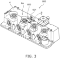
- Fig. 3 is a perspective view illustrating the temperature raising mechanism for the blow-by gas treatment device according to the First Embodiment of the present invention.
- Fig. 4 is a sectional view illustrating an internal structure example of heating means and the head cover on a B-B line in Fig. 3 .
- the temperature raising mechanism 800 for the blow-by gas treatment device has the head cover 4, the blow-by gas treatment device 100, and the heating means 600.
- the heating means 600 is replaceably fixed to the outer surface in the vicinity of the upper surface part 4A of the head cover 4 by using a mounting bolt 601.
- the separating portion 330 of the blow-by gas treatment device 100 is also called an impactor-type separator and has the impactor 120, a filter 130, a collision plate 133, and screws 139, 139 for mounting. As illustrated in Fig. 2 , the separating portion 330 is provided at the center position RP in the front-back direction of the engine 1.
- the partition wall part 200 is provided inside the head cover 4.
- the partition wall part 200 is fixed to the head cover 4 and has a throttle hole 121 of the impactor 120 and a substantially L-shaped section type heat-conduction assisting portion 199.
- the separating portion 330 is provided with inclination only by a predetermined inclination angle ⁇ with respect to a horizontal plane along the X-Y plane in the partition wall part 200. Specifically, as shown in Fig. 2 , the separating portion 330 is provided with inclination in a direction in which the oil OL separated from the blow-by gas BG by the separating portion 330 is guided to the first oil guide-groove portion 151 and the second oil guide-groove portion 152.
- an upper surface 122 of the impactor 120 is inclined only by a predetermined inclination angle ⁇ with respect to the horizontal plane along the X-Y plane.
- the upper surface 122 of the impactor 120 is inclined downward toward the first oil guide-groove portion 151 and the second oil guide-groove portion 152.
- the upper surface 122 of the impactor 120 of this Embodiment is an example of a "surface of the flow-velocity raising operation portion" of the present invention.
- the separating portion 330 does not necessarily have to be inclined with respect to the horizontal plane along the X-Y plane but may be provided in parallel to the horizontal plane along the X-Y plane.
- the upper surface 122 of the impactor 120 may be parallel to the horizontal plane along the X-Y plane.
- the filter 130 and the collision plate 133 are placed on a setting portion 400 provided on the upper surface 122 of the impactor 120.
- the inclination angle ⁇ is approximately 5 degrees or more and 45 degrees or less, for example. If the inclination angle ⁇ is smaller than 5 degrees, the oil OL separated from the blow-by gas BG by the separating portion 330 cannot be rapidly guided to the first oil guide-groove portion 151 and the second oil guide-groove portion 152 via an oil outlet inclination-guiding portion 500. Alternatively, if the inclination angle ⁇ is larger than 45 degrees, an effective opening area of an inlet part of the throttle hole 121 of the impactor 120 is narrowed, and the blow-by gas BG cannot be easily guided to the impactor 120.
- the impactor 120 shown in Fig. 2 and Fig. 4 has a function of a nozzle or an orifice and preferably has at least two penetrating throttle holes 121.
- An axial direction of the throttle hole 121 does not follow the vertical direction or the up-down direction, which is the Z-direction, but is inclined only by the aforementioned inclination angle ⁇ with respect to the Z-direction.
- the impactor 120 is a flow-velocity raising operation portion which can raise the flow velocity of the blow-by gas BG by causing the blow-by gas BG to pass diagonally upward along the throttle hole 121.
- the impactor 120 is provided at the center position RP in the front-back direction of the engine 1.
- the blow-by gas BG taken in by the first blow-by gas taking-in portion 111 and the blow-by gas BG taken in by the second blow-by gas taking-in portion 112 are uniformly guided to the impactor 120.
- the impactor 120 raises the flow velocity of the blow-by gas BG flowing into the throttle hole 121 and then, guides the blow-by gas BG to the filter 130.
- the filter 130 is made of a material such as glass wool, for example.
- the filter 130 is fixed by the mounting screw 139 so as to be sandwiched between the collision plate 133 and the setting portion 400 of the impactor 120.
- the collision plate 133 is a metal plate such as an iron plate, for example.
- the blow-by gas BG flows into the throttle hole 121 of the impactor 120 and diagonally rises, whereby the flow velocity is raised.
- the blow-by gas BG whose flow velocity has been raised passes through the filter 130, where foreign substances are removed, collides against the lower surface of the collision plate 133, and is separated into the oil OL and the gas G.
- the gas G separated from the blow-by gas BG by the separating portion 330 is emitted from the filter 130.
- the gas G not containing a mist of the oil OL emitted from the filter 130 is guided by the guide wall part 203, passes through a path 135 of the upper region 4Q and is led to the outlet portion 40.
- the oil OL separated from the blow-by gas BG by the separating portion 330 drops through the filter 130 in Fig. 2 and drops onto the upper surface 122 of the impactor 120.
- the oil OL having dropped onto the upper surface 122 of the impactor 120 flows along the upper surface 122 of the impactor 120 and flows toward the first oil guide-groove portion 151 and the second oil guide-groove portion 152.
- a PTC heater (Positive temperature coefficient heater) is preferably used.
- the heating means 600 is not limited to the PTC heater.
- the PTC heater is a heating body using a semiconductor ceramic material with barium titanate (BaTiOs) as a main component and has a positive temperature characteristic.
- the PTC heater can rapidly increase a resistance value at a temperature (Curie temperature) when the temperature rises by combining another component with the main component.
- the heating means 600 shown in Fig. 4 when a voltage is applied in accordance with an instruction of a control portion 180, a large amount of the electric current flows at a low temperature so as to increase a heat generation amount, and as the heat is generated, the resistance value increases, the electric current is limited, and the heat generation amount is suppressed.
- the temperature of the heating means 600 does not rise to a temperature higher than a vicinity of a Curie point temperature.
- the Curie point temperature of the heating means 600 of this Embodiment is a temperature lower than a temperature at which the oil OL contained in the blow-by gas BG is carbonized and is 85°C to 105°C, for example.
- the PTC heater is small-sized and has a low power consumption, it is effective for a device on which the engine 1 shown in Fig. 1 is mounted to avoid freezing of moisture contained in the oil OL at a low temperature in the impactor 120 by a large heat generation amount.
- the heating means 600 is disposed with inclination with respect to the head cover 4. Specifically, the heating means 600 is inclined only by an inclination angle ⁇ with respect to the X-Y plane as shown in Fig. 4 . That is, the heating means 600 is provided with inclination by the inclination angle ⁇ of 45 degrees, for example, along a direction crossing the X-Y plane including the axial direction of the crank shaft 9 of the engine 1 shown in Fig. 1 .
- the inclination angle ⁇ is not limited to 45 degrees, but an arbitrary angle can be set.
- the heating means 600 is mounted by screwing the mounting bolt 601 to a female thread part 4V of an inclined thick part 4W of the head cover 4. The heating means 600 can be replaced if the heating means 600 fails, for example, by removing the mounting bolt 601.
- the head cover 4 has a heat conducting portion 700.
- the heat conducting portion 700 has an inclined part 701 and a thick part 702 for heat conduction.
- the thick part 702 for heat conduction of the heat conducting portion 700 is in contact with the heat-conduction assisting portion 199 of the partition wall part 200.
- a mounting plane 703 is formed on outer surfaces of the inclined part 701 and the thick part 702 for heat conduction.
- the mounting plane 703 in this Embodiment is an example of the "outer surface of the head cover" of the present invention.
- the heating means 600 of this Embodiment is placed and fixed to the mounting plane 703.
- the heating means 600 is disposed with inclination with respect to the head cover 4.
- the mounting plane 703 is inclined with respect to an upper surface 199A of the heat-conduction assisting portion 199.
- An angle between the mounting plane 703 and the upper surface 199A of the heat-conduction assisting portion 199 corresponds to the aforementioned inclination angle ⁇ . Therefore, by using a space between the head cover 4 and the separating portion 330, the thick part 702 for heat conduction of the heat conducting portion 700 which is thicker than the other parts of the head cover 4 can be provided. Therefore, the heat generated by the heating means 600 is efficiently conducted to the separating portion 330 through the thick part 702 for heat conduction of the heat conducting portion 700.
- the inclined part 701 is formed between the inclined thick part 4W and the thick part 702 for heat conduction and is not in contact with the heat-conduction assisting portion 199 of the partition wall part 200.
- the inclined part 701 of this Embodiment is an example of "the other parts in the heat conducting portion not in contact with the partition wall part" of the present invention.
- the thickness of the inclined part 701 is smaller than the thickness of the inclined thick part 4W.
- the thickness of the thick part 702 for heat conduction is set larger than the thickness of the inclined part 701.
- an inner surface 701N of the inclined part 701 is inclined by the inclination angle ⁇ .
- an inner surface 702M of the thick part 702 for heat conduction is formed perpendicular along the X-Z plane.
- the thick part 702 for heat conduction has a function of directly conducting the heat generated by a PTC element portion 602 along a heat conduction path RR indicated by an arrow to the heat-conduction assisting portion 199 of the partition wall part 200.
- the heat generated by the PTC element portion 602 can be reliably conducted to the two throttle holes 121 of the separating portion 330 via the heat-conduction assisting portion 199 along the heat conduction path RR.
- the heat-conduction assisting portion 199 of the partition wall part 200 is in contact with the heat conducting portion 700 of the head cover 4, receives the heat generated by the heating means 600 via the heat conducting portion 700, and conducts it to the separating portion 330.
- the heating means 600 includes the PTC element portion 602, a circuit board, and a required circuit element.
- a heat generating surface of the PTC element portion 602 is in close contact with the mounting plane 703 of the heat conducting portion 700 of the head cover 4.
- a lower surface 702D of the thick part 702 for heat conduction is mechanically and moreover, thermally in close contact with the heat-conduction assisting portion 199 of the partition wall part 200.
- the aforementioned heating means 600 is not equipped in the head cover 4, there is a concern that the two throttle holes 121 of the separating portion 330 in a region ST indicated by a broken line illustrated in Fig. 4 are blocked by freezing of the moisture contained in the oil OL of the blow-by gas BG. If the two throttle holes 121 are blocked, there is a concern that an internal pressure of the crank case 6 rises, and an optional seal portion provided in the engine 1 is broken.
- the thick part 702 for heat conduction of the heat conducting portion 700 conducts heat generated by the PTC element portion 602 of the heating means 600 directly to the heat-conduction assisting portion 199 of the partition wall part 200 along the heat conduction path RR indicated by the arrow.
- the heat generated by the PTC element portion 602 can be reliably conducted to the two throttle holes 121 of the separating portion 330 via the heat-conduction assisting portion 199.
- the blockage of the two throttle holes 121 of the separating portion 330 in the region ST indicated by the broken line shown in Fig. 4 by the freezing of the moisture contained in the oil OL of the blow-by gas BG can be prevented. Therefore, a rise of the internal pressure of the crank case 6 can be suppressed, and the breakage of the optional seal portion provided in the engine 1 can be suppressed.
- the thick part 702 for heat conduction is set larger than the thickness of the inclined part 701
- a sectional area of the thick part 702 for heat conduction is set larger than a sectional area of the inclined part 701. Since outside air temperatures of the thick part 702 for heat conduction and the inclined part 701 are substantially the same, the thick part 702 for heat conduction having a relatively larger sectional area can conduct the heat generated by the PTC element portion 602 more easily than the inclined part 701 having a relatively smaller sectional area. Thus, the heat generated by the PTC element portion 602 can be conducted directly and more reliably to the thick part 702 for heat conduction and the heat-conduction assisting portion 199 of the partition wall part 200 along the heat conduction path RR indicated by the arrow.
- the temperature in the vicinity of the throttle hole 121 is set to approximately 0°C, and a far higher temperature than 0°C such as 10°C or more, for example, does not have to be set.
- the heat generated by the PTC element portion 602 is conducted to the two throttle holes 121 of the separating portion 330 via the thick part 702 for heat conduction and the heat-conduction assisting portion 199, as compared with the case where the heating means 600 directly heats the parts of the two throttle holes 121 of the separating portion 330, the part of the two throttle holes 121 of the separating portion 330 can be suppressed from rising to a high temperature.
- the carbonization of the oil OL part in the blow-by gas BG can be prevented. Therefore, a blockage risk that the carbonized oil blocks the throttle hole 121 can be also avoided.
- the heating means 600 when the heating means 600 is installed inside the head cover 4, a sealing performance is needed for the part of the heating means 600 inserted into the head cover 4, but in this Embodiment, since the heating means 600 is mounted on the mounting plane 703 as the outer surface of the head cover 4, the structure of the head cover 4 can be suppressed from becoming complicated.
- the heat conducting portion 700 of the head cover 4 is in contact with the partition wall part 200 and conducts the heat generated by the heating means 600 to the separating portion 330.
- the temperature raising mechanism 800 for the blow-by gas treatment device according to this Embodiment can suppress the freezing of the moisture contained in the blow-by gas BG at a low temperature in the separating portion 330.
- the heat generated by the heating means 600 is not directly conducted to the separating portion 330 but is conducted to the separating portion 330 via the heat conducting portion 700 of the head cover 4 in contact with the partition wall part 200 of the blow-by gas treatment device 100.
- the temperature raising mechanism 800 for the blow-by gas treatment device suppresses the separating portion 330 from becoming a high temperature, while it can suppress the freezing of the moisture contained in the blow-by gas BG at a low temperature in the separating portion 330, while the oil OL contained in the blow-by gas BG is carbonized.
- the mounting plane 703 of the head cover 4 to which the heating means 600 is fixed is inclined with respect to the upper surface 199A of the heat-conduction assisting portion 199 of the partition wall part 200.
- a space for forming the heat conducting portion 700 of the head cover 4 thicker than the other parts of the head cover 4 can be ensured inside the head cover 4.
- the heat conducting portion 700 which is thicker than the other parts of the head cover 4 is provided, and the contact area between the heat conducting portion 700 of the head cover 4 and the heat-conduction assisting portion 199 of the partition wall part 200 can be set wider.
- the temperature raising mechanism 800 for the blow-by gas treatment device can efficiently conduct the heat generated by the heating means 600 to the separating portion 330 via the heat conducting portion 700 of the head cover 4 and the heat-conduction assisting portion 199 of the partition wall part 200 and can further suppress the freezing of the moisture contained in the blow-by gas BG at a low temperature in the separating portion 330.
- the heating means 600 when the heating means 600 is the PTC heater, it has a resistance value which rapidly increases at a certain temperature, when the temperature rises. In this case, in the heating means 600, a large amount of the electric current flows at a low temperature so as to increase the heat generation amount, and as the heat is generated, the resistance value increases, the electric current is limited, and the heat generation amount can be suppressed. Therefore, the temperature raising mechanism 800 for the blow-by gas treatment device according to this Embodiment can suppress the freezing of the moisture contained in the blow-by gas BG at a low temperature in the separating portion 330, while the separating portion 330 is suppressed from becoming a high temperature, and carbonization of the oil OL contained in the blow-by gas BG is suppressed.
- the thickness of the thick part 702 for heat conduction in the heat conducting portion 700 in contact with the partition wall part 200 is larger than the thickness of the inclined part 701 in the heat conducting portion 700 not in contact with the partition wall part 200.
- the heat generated by the heating means 600 is conducted to the thick part 702 for heat conduction more easily than the inclined part 701.
- a heat capacity of the thick part for heat conduction can be increased.
- the temperature raising mechanism 800 for the blow-by gas treatment device efficiently conducts the heat generated by the heating means 600 to the separating portion 330 and can further suppress the freezing of the moisture contained in the blow-by gas BG at a low temperature in the separating portion 330.
- the temperature raising mechanism 800 for the blow-by gas treatment device can suppress staying of the oil OL in the separating portion 330 and suppress the freezing of the moisture contained in the oil OL of the blow-by gas BG at a low temperature in the separating portion 330.
- the impactor 120 as the flow-velocity raising operation portion causes the blow-by gas BG to collide against the collision plate 133 while the flow velocity of the blow-by gas BG is caused to rise along the direction inclined with respect to the vertical direction (up-down direction).
- the blow-by gas BG is reliably separated into the oil OL and the gas G.
- the oil OL separated from the blow-by gas BG at the collision plate 133 passes through the filter 130 and drops onto the upper surface 122 of the impactor 120 opposed to the collision plate 133.
- the upper surface 122 of the impactor 120 is inclined downward toward the first oil guide-groove portion 151 and the second oil guide-groove portion 152.
- the temperature raising mechanism 800 for the blow-by gas treatment device suppresses staying of the oil OL in the separating portion 330 and can suppress the freezing of the moisture contained in the oil OL of the blow-by gas BG at a low temperature in the separating portion 330.
- Fig. 5 is a perspective view illustrating a temperature raising mechanism for a blow-by gas treatment device according to the Second Embodiment of the present invention.
- Fig. 6 is a sectional view illustrating an internal structure example of heating means and a head cover on a C-C line in Fig. 5 .
- heating means 600 is provided with inclination by the inclination angle ⁇ with respect to the head cover 4.
- heating means 600A is provided along substantially a perpendicular direction with respect to a head cover 4X, that is, substantially the perpendicular direction with respect to the X-Y plane substantially including an axial direction of the crank shaft 9.
- the mounting plane 703 is perpendicular to an upper surface 199A of the heat-conduction assisting portion 199. This point is different from the case of the heating means 600 in the First Embodiment.
- the heating means 600A includes the PTC element portion 602, a circuit board, and a required circuit element.
- a heat generating surface of the PTC element portion 602 is in close contact with the mounting plane 703 of a heat conducting portion 700A of the head cover 4X.
- the heat conducting portion 700A is a thick part formed substantially perpendicularly and has a rectangular sectional shape.
- a lower surface 702F of the heat conducting portion 700A is mechanically and moreover, thermally in close contact with the heat-conduction assisting portion 199 of the partition wall part 200.
- the heat conducting portion 700A has a function of directly conducting the heat generated by the PTC element portion 602 to the heat-conduction assisting portion 199 of the partition wall part 200 along the heat conduction path RR indicated by an arrow. As a result, the heat generated by the PTC element portion 602 can be conducted to the two throttle holes 121 of the separating portion 330 via the heat-conduction assisting portion 199.
- the thickness of the heat conducting portion 700A is set larger than the thickness of the other parts. Therefore, the heat conducting portion 700A can conduct the heat generated by the PTC element portion 602 to the two throttle holes 121 of the separating portion 330 via the heat-conduction assisting portion 199 more easily.
- the heating means 600A is provided simply in the up-down direction (vertical direction). And the heat generated by the heating means 600A can be efficiently conducted via the heat conducting portion 700A. Thus, the heat generated by the heating means 600A can be efficiently conducted to the two throttle holes 121 of the separating portion 330 via the heat-conduction assisting portion 199, while a disposition structure of the heating means 600A is simplified. Since the thickness of the heat conducting portion 700A is larger than the thickness of the other parts of the head cover 4, the heat capacity of the heat conducting portion 700A can be increased, and the heat generated by the heating means 600A can be efficiently conducted to the separating portion 330.
- the mounting plane 703 of the head cover 4 to which the heating means 600 is fixed is perpendicular to the upper surface 199A of the heat-conduction assisting portion 199.
- a contact area between the heat conducting portion 700 of the head cover 4 and the heat-conduction assisting portion 199 of the partition wall part 200 can be ensured, while the disposition structure of the heating means 600 is simplified.
- the temperature raising mechanism 800A for the blow-by gas treatment device can efficiently conduct the heat generated by the heating means 600 to the separating portion 330 via the heat conducting portion 700 of the head cover 4 and the heat-conduction assisting portion 199 of the partition wall part 200, while complication of the disposition structure of the heating means 600 is suppressed.
- the present invention is not limited to the aforementioned Embodiments but is capable of various changes within a range not departing from the scope of claims.
- the configurations of the aforementioned Embodiments may be partially omitted or combined arbitrarily so as to be different from the above.
- the heating means 600, 600A use the PTC heater, for example, but other types of the heating means such as the one with a structure in which an electrothermal wire is disposed on a circuit board, for example, may be employed and not particularly limited.
- the separating portion 330 is disposed with inclination in the illustrated examples but may be disposed horizontally along the X-Y plane.
- the engine 1 As an example of the engine of the present invention, the engine 1 according to this Embodiment is exemplified.
- the engine 1 is a supercharging type diesel engine with a turbocharger.
- the engine of the present invention may be a natural-intake type diesel engine, a supercharging type gasoline engine with a turbocharger, a natural-intake gasoline engine and the like.
Landscapes
- Engineering & Computer Science (AREA)
- Mechanical Engineering (AREA)
- General Engineering & Computer Science (AREA)
- Lubrication Details And Ventilation Of Internal Combustion Engines (AREA)
- Cylinder Crankcases Of Internal Combustion Engines (AREA)
Applications Claiming Priority (2)
| Application Number | Priority Date | Filing Date | Title |
|---|---|---|---|
| JP2021093254A JP7275423B2 (ja) | 2021-06-02 | 2021-06-02 | ブローバイガス処理装置の昇温機構およびブローバイガス処理装置の昇温機構を備えるエンジン |
| PCT/JP2022/007025 WO2022254820A1 (fr) | 2021-06-02 | 2022-02-21 | Mécanisme d'élévation de température destiné à un dispositif de traitement de gaz par soufflage et moteur doté de celui-ci |
Publications (3)
| Publication Number | Publication Date |
|---|---|
| EP4350131A1 true EP4350131A1 (fr) | 2024-04-10 |
| EP4350131A4 EP4350131A4 (fr) | 2024-10-16 |
| EP4350131B1 EP4350131B1 (fr) | 2026-03-25 |
Family
ID=84324117
Family Applications (1)
| Application Number | Title | Priority Date | Filing Date |
|---|---|---|---|
| EP22815579.2A Active EP4350131B1 (fr) | 2021-06-02 | 2022-02-21 | Mécanisme d'élévation de température destiné à un dispositif de traitement de gaz par soufflage et moteur doté de celui-ci |
Country Status (5)
| Country | Link |
|---|---|
| US (1) | US20240287922A1 (fr) |
| EP (1) | EP4350131B1 (fr) |
| JP (1) | JP7275423B2 (fr) |
| CN (1) | CN117355665A (fr) |
| WO (1) | WO2022254820A1 (fr) |
Families Citing this family (1)
| Publication number | Priority date | Publication date | Assignee | Title |
|---|---|---|---|---|
| JP2025123956A (ja) | 2024-02-13 | 2025-08-25 | トヨタ自動車株式会社 | 車両 |
Family Cites Families (10)
| Publication number | Priority date | Publication date | Assignee | Title |
|---|---|---|---|---|
| JP2001336412A (ja) | 2000-05-24 | 2001-12-07 | Aichi Mach Ind Co Ltd | ブローバイガス通路 |
| JP2006194105A (ja) | 2005-01-11 | 2006-07-27 | Toyota Motor Corp | シリンダヘッドカバーおよび内燃機関 |
| JP2013133779A (ja) | 2011-12-27 | 2013-07-08 | Sanoh Industrial Co Ltd | ブローバイガス還流装置 |
| JP6135102B2 (ja) | 2012-11-22 | 2017-05-31 | アイシン精機株式会社 | ブローバイガス還元装置 |
| JP2017141769A (ja) * | 2016-02-12 | 2017-08-17 | 株式会社クボタ | ブローバイガス還流装置 |
| US20180051605A1 (en) | 2016-08-16 | 2018-02-22 | Caterpillar Inc. | Conduit for maintaining temperature of fluid |
| JP6774388B2 (ja) * | 2017-06-29 | 2020-10-21 | 株式会社クボタ | エンジンのブリーザ装置 |
| JP6826009B2 (ja) * | 2017-08-08 | 2021-02-03 | 株式会社ニフコ | オイルセパレータ |
| JP7157012B2 (ja) * | 2019-06-21 | 2022-10-19 | 株式会社クボタ | ブローバイガス還流装置付エンジン |
| JP7109405B2 (ja) * | 2019-06-30 | 2022-07-29 | 株式会社クボタ | ブローバイガス還流装置 |
-
2021
- 2021-06-02 JP JP2021093254A patent/JP7275423B2/ja active Active
-
2022
- 2022-02-21 EP EP22815579.2A patent/EP4350131B1/fr active Active
- 2022-02-21 WO PCT/JP2022/007025 patent/WO2022254820A1/fr not_active Ceased
- 2022-02-21 CN CN202280036367.1A patent/CN117355665A/zh active Pending
- 2022-02-21 US US18/565,165 patent/US20240287922A1/en active Pending
Also Published As
| Publication number | Publication date |
|---|---|
| US20240287922A1 (en) | 2024-08-29 |
| EP4350131A4 (fr) | 2024-10-16 |
| CN117355665A (zh) | 2024-01-05 |
| EP4350131B1 (fr) | 2026-03-25 |
| WO2022254820A1 (fr) | 2022-12-08 |
| JP2022185513A (ja) | 2022-12-14 |
| JP7275423B2 (ja) | 2023-05-18 |
Similar Documents
| Publication | Publication Date | Title |
|---|---|---|
| ES2359882T3 (es) | Refrigerador de aire de sobrealimentación con desagüe de condensado. | |
| JP5394536B2 (ja) | 燃焼機関において排気ガスを戻す構造 | |
| US20170362995A1 (en) | Vehicle air intake system | |
| CN113653575B (zh) | 一种具有低压egr系统的发动机总成及冷凝水控制策略 | |
| CN1181457A (zh) | 液化燃料汽化装置及带该装置的燃气发动机 | |
| EP4350131A1 (fr) | Mécanisme d'élévation de température destiné à un dispositif de traitement de gaz par soufflage et moteur doté de celui-ci | |
| US10184444B2 (en) | Method for improving the cold start capacity of an internal combustion engine, and crankcase ventilating device for this purpose | |
| CN101353976B (zh) | 发动机及摩托车发动机 | |
| JP6606462B2 (ja) | ブローバイガス処理装置 | |
| JP2022056070A (ja) | ブローバイガス処理装置およびブローバイガス処理装置を備えるエンジン | |
| CN111379610B (zh) | 气缸盖罩 | |
| JP6633461B2 (ja) | 産業用エンジン | |
| JP7385091B2 (ja) | ブローバイガス処理装置およびブローバイガス処理装置を備えるエンジン | |
| JP7613824B2 (ja) | ブローバイガス処理装置およびブローバイガス処理装置を備えるエンジン | |
| JP6621713B2 (ja) | オイルセパレータ付エンジン | |
| US11635006B2 (en) | Blow-by gas recirculation device | |
| JP2012036738A (ja) | ブローバイガス還流装置 | |
| WO2007126562A1 (fr) | Moteur et procédé pour faire fonctionner un moteur | |
| JP7103936B2 (ja) | ブローバイガス還流装置 | |
| CN109219691B (zh) | 引擎装置 | |
| US20250320828A1 (en) | Engine | |
| CN112523890B (zh) | 发动机气缸盖罩 | |
| JP7385353B2 (ja) | 内燃機関 | |
| JP2020012449A (ja) | 排気還流ガスの還流機構 | |
| JP7232055B2 (ja) | ブローバイガス還流装置付きエンジン |
Legal Events
| Date | Code | Title | Description |
|---|---|---|---|
| STAA | Information on the status of an ep patent application or granted ep patent |
Free format text: STATUS: THE INTERNATIONAL PUBLICATION HAS BEEN MADE |
|
| PUAI | Public reference made under article 153(3) epc to a published international application that has entered the european phase |
Free format text: ORIGINAL CODE: 0009012 |
|
| STAA | Information on the status of an ep patent application or granted ep patent |
Free format text: STATUS: REQUEST FOR EXAMINATION WAS MADE |
|
| 17P | Request for examination filed |
Effective date: 20231127 |
|
| AK | Designated contracting states |
Kind code of ref document: A1 Designated state(s): AL AT BE BG CH CY CZ DE DK EE ES FI FR GB GR HR HU IE IS IT LI LT LU LV MC MK MT NL NO PL PT RO RS SE SI SK SM TR |
|
| DAV | Request for validation of the european patent (deleted) | ||
| DAX | Request for extension of the european patent (deleted) | ||
| A4 | Supplementary search report drawn up and despatched |
Effective date: 20240916 |
|
| RIC1 | Information provided on ipc code assigned before grant |
Ipc: F02F 7/00 20060101ALI20240910BHEP Ipc: F01M 13/04 20060101ALI20240910BHEP Ipc: F01M 13/00 20060101AFI20240910BHEP |
|
| GRAP | Despatch of communication of intention to grant a patent |
Free format text: ORIGINAL CODE: EPIDOSNIGR1 |
|
| STAA | Information on the status of an ep patent application or granted ep patent |
Free format text: STATUS: GRANT OF PATENT IS INTENDED |
|
| INTG | Intention to grant announced |
Effective date: 20251015 |
|
| GRAS | Grant fee paid |
Free format text: ORIGINAL CODE: EPIDOSNIGR3 |
|
| GRAA | (expected) grant |
Free format text: ORIGINAL CODE: 0009210 |
|
| STAA | Information on the status of an ep patent application or granted ep patent |
Free format text: STATUS: THE PATENT HAS BEEN GRANTED |
|
| AK | Designated contracting states |
Kind code of ref document: B1 Designated state(s): AL AT BE BG CH CY CZ DE DK EE ES FI FR GB GR HR HU IE IS IT LI LT LU LV MC MK MT NL NO PL PT RO RS SE SI SK SM TR |
|
| REG | Reference to a national code |
Ref country code: CH Ref legal event code: F10 Free format text: ST27 STATUS EVENT CODE: U-0-0-F10-F00 (AS PROVIDED BY THE NATIONAL OFFICE) Effective date: 20260325 Ref country code: GB Ref legal event code: FG4D |
|
| REG | Reference to a national code |
Ref country code: DE Ref legal event code: R096 Ref document number: 602022033109 Country of ref document: DE |
|
| REG | Reference to a national code |
Ref country code: IE Ref legal event code: FG4D |