EP4350139B1 - Procédé de commande d'un système d'injection de carburant - Google Patents
Procédé de commande d'un système d'injection de carburant Download PDFInfo
- Publication number
- EP4350139B1 EP4350139B1 EP23201578.4A EP23201578A EP4350139B1 EP 4350139 B1 EP4350139 B1 EP 4350139B1 EP 23201578 A EP23201578 A EP 23201578A EP 4350139 B1 EP4350139 B1 EP 4350139B1
- Authority
- EP
- European Patent Office
- Prior art keywords
- fuel
- pressure
- pumping chamber
- intake valve
- control method
- Prior art date
- Legal status (The legal status is an assumption and is not a legal conclusion. Google has not performed a legal analysis and makes no representation as to the accuracy of the status listed.)
- Active
Links
Images


Classifications
-
- F—MECHANICAL ENGINEERING; LIGHTING; HEATING; WEAPONS; BLASTING
- F02—COMBUSTION ENGINES; HOT-GAS OR COMBUSTION-PRODUCT ENGINE PLANTS
- F02D—CONTROLLING COMBUSTION ENGINES
- F02D41/00—Electrical control of supply of combustible mixture or its constituents
- F02D41/30—Controlling fuel injection
- F02D41/38—Controlling fuel injection of the high pressure type
- F02D41/3809—Common rail control systems
- F02D41/3836—Controlling the fuel pressure
-
- F—MECHANICAL ENGINEERING; LIGHTING; HEATING; WEAPONS; BLASTING
- F02—COMBUSTION ENGINES; HOT-GAS OR COMBUSTION-PRODUCT ENGINE PLANTS
- F02D—CONTROLLING COMBUSTION ENGINES
- F02D41/00—Electrical control of supply of combustible mixture or its constituents
- F02D41/02—Circuit arrangements for generating control signals
- F02D41/04—Introducing corrections for particular operating conditions
- F02D41/042—Introducing corrections for particular operating conditions for stopping the engine
-
- F—MECHANICAL ENGINEERING; LIGHTING; HEATING; WEAPONS; BLASTING
- F02—COMBUSTION ENGINES; HOT-GAS OR COMBUSTION-PRODUCT ENGINE PLANTS
- F02D—CONTROLLING COMBUSTION ENGINES
- F02D41/00—Electrical control of supply of combustible mixture or its constituents
- F02D41/30—Controlling fuel injection
- F02D41/38—Controlling fuel injection of the high pressure type
- F02D41/3809—Common rail control systems
- F02D41/3836—Controlling the fuel pressure
- F02D41/3845—Controlling the fuel pressure by controlling the flow into the common rail, e.g. the amount of fuel pumped
- F02D41/3854—Controlling the fuel pressure by controlling the flow into the common rail, e.g. the amount of fuel pumped with elements in the low pressure part, e.g. low pressure pump
-
- F—MECHANICAL ENGINEERING; LIGHTING; HEATING; WEAPONS; BLASTING
- F02—COMBUSTION ENGINES; HOT-GAS OR COMBUSTION-PRODUCT ENGINE PLANTS
- F02M—SUPPLYING COMBUSTION ENGINES IN GENERAL WITH COMBUSTIBLE MIXTURES OR CONSTITUENTS THEREOF
- F02M59/00—Pumps specially adapted for fuel-injection and not provided for in groups F02M39/00 -F02M57/00, e.g. rotary cylinder-block type of pumps
- F02M59/44—Details, components parts, or accessories not provided for in, or of interest apart from, the apparatus of groups F02M59/02 - F02M59/42; Pumps having transducers, e.g. to measure displacement of pump rack or piston
-
- F—MECHANICAL ENGINEERING; LIGHTING; HEATING; WEAPONS; BLASTING
- F02—COMBUSTION ENGINES; HOT-GAS OR COMBUSTION-PRODUCT ENGINE PLANTS
- F02M—SUPPLYING COMBUSTION ENGINES IN GENERAL WITH COMBUSTIBLE MIXTURES OR CONSTITUENTS THEREOF
- F02M59/00—Pumps specially adapted for fuel-injection and not provided for in groups F02M39/00 -F02M57/00, e.g. rotary cylinder-block type of pumps
- F02M59/44—Details, components parts, or accessories not provided for in, or of interest apart from, the apparatus of groups F02M59/02 - F02M59/42; Pumps having transducers, e.g. to measure displacement of pump rack or piston
- F02M59/46—Valves
-
- F—MECHANICAL ENGINEERING; LIGHTING; HEATING; WEAPONS; BLASTING
- F02—COMBUSTION ENGINES; HOT-GAS OR COMBUSTION-PRODUCT ENGINE PLANTS
- F02D—CONTROLLING COMBUSTION ENGINES
- F02D2250/00—Engine control related to specific problems or objectives
- F02D2250/31—Control of the fuel pressure
-
- F—MECHANICAL ENGINEERING; LIGHTING; HEATING; WEAPONS; BLASTING
- F02—COMBUSTION ENGINES; HOT-GAS OR COMBUSTION-PRODUCT ENGINE PLANTS
- F02M—SUPPLYING COMBUSTION ENGINES IN GENERAL WITH COMBUSTIBLE MIXTURES OR CONSTITUENTS THEREOF
- F02M59/00—Pumps specially adapted for fuel-injection and not provided for in groups F02M39/00 -F02M57/00, e.g. rotary cylinder-block type of pumps
- F02M59/20—Varying fuel delivery in quantity or timing
- F02M59/36—Varying fuel delivery in quantity or timing by variably-timed valves controlling fuel passages to pumping elements or overflow passages
- F02M59/366—Valves being actuated electrically
- F02M59/368—Pump inlet valves being closed when actuated
-
- F—MECHANICAL ENGINEERING; LIGHTING; HEATING; WEAPONS; BLASTING
- F02—COMBUSTION ENGINES; HOT-GAS OR COMBUSTION-PRODUCT ENGINE PLANTS
- F02M—SUPPLYING COMBUSTION ENGINES IN GENERAL WITH COMBUSTIBLE MIXTURES OR CONSTITUENTS THEREOF
- F02M59/00—Pumps specially adapted for fuel-injection and not provided for in groups F02M39/00 -F02M57/00, e.g. rotary cylinder-block type of pumps
- F02M59/44—Details, components parts, or accessories not provided for in, or of interest apart from, the apparatus of groups F02M59/02 - F02M59/42; Pumps having transducers, e.g. to measure displacement of pump rack or piston
- F02M59/442—Details, components parts, or accessories not provided for in, or of interest apart from, the apparatus of groups F02M59/02 - F02M59/42; Pumps having transducers, e.g. to measure displacement of pump rack or piston means preventing fuel leakage around pump plunger, e.g. fluid barriers
-
- F—MECHANICAL ENGINEERING; LIGHTING; HEATING; WEAPONS; BLASTING
- F02—COMBUSTION ENGINES; HOT-GAS OR COMBUSTION-PRODUCT ENGINE PLANTS
- F02M—SUPPLYING COMBUSTION ENGINES IN GENERAL WITH COMBUSTIBLE MIXTURES OR CONSTITUENTS THEREOF
- F02M59/00—Pumps specially adapted for fuel-injection and not provided for in groups F02M39/00 -F02M57/00, e.g. rotary cylinder-block type of pumps
- F02M59/44—Details, components parts, or accessories not provided for in, or of interest apart from, the apparatus of groups F02M59/02 - F02M59/42; Pumps having transducers, e.g. to measure displacement of pump rack or piston
- F02M59/46—Valves
- F02M59/464—Inlet valves of the check valve type
-
- F—MECHANICAL ENGINEERING; LIGHTING; HEATING; WEAPONS; BLASTING
- F02—COMBUSTION ENGINES; HOT-GAS OR COMBUSTION-PRODUCT ENGINE PLANTS
- F02M—SUPPLYING COMBUSTION ENGINES IN GENERAL WITH COMBUSTIBLE MIXTURES OR CONSTITUENTS THEREOF
- F02M59/00—Pumps specially adapted for fuel-injection and not provided for in groups F02M39/00 -F02M57/00, e.g. rotary cylinder-block type of pumps
- F02M59/44—Details, components parts, or accessories not provided for in, or of interest apart from, the apparatus of groups F02M59/02 - F02M59/42; Pumps having transducers, e.g. to measure displacement of pump rack or piston
- F02M59/46—Valves
- F02M59/466—Electrically operated valves, e.g. using electromagnetic or piezoelectric operating means
Definitions
- This invention relates to a method to control a fuel injection system; preferably, the direct injection system is used in a spark-ignition internal combustion engine and, thus, is powered by petrol or similar fuels.
- the high-pressure fuel pump described in the patent application EP2236809A1 comprises: a main body, a pumping chamber made in the main body and inside of which a piston slides with reciprocating motion, an intake duct adjusted by an intake valve to supply the fuel at low pressure inside the pumping chamber, and a delivery duct adjusted by a delivery valve to supply the fuel at high pressure outside the pumping chamber and towards the common rail.
- a modern vehicle normally implements the "Start & Stop" system that, to reduce the consumption of fuel during city use, stops and starts the internal combustion engine automatically when the vehicle is stopped, typically due to a red light (generally the internal combustion engine remains stopped for a few tens of seconds or even for some minutes).
- the pressure of the fuel in the common rail remains basically unchanged.
- EP2187038A1 and DE102008042371A1 describe a high-pressure fuel pump for an internal combustion engine; when the internal combustion engine is stopped (shut off), the fuel pump is controlled so as to reduce the pressure of the fuel in a high-pressure supply system.
- the purpose of this invention is to provide a control method of a fuel injection system reducing the leakage of fuel through the delivery valve of the high-pressure fuel pump and through the pressure relief valve of the high-pressure fuel pump when the internal combustion engine is stopped and, at the same time, is easy and fast to implement.
- reference number 1 denotes, as a whole, a direct fuel injection system of the common rail type for an internal combustion engine.
- the direct injection system 1 comprises multiple injectors 2, a common rail 3 that supplies the pressurised fuel to the injectors 2, a high-pressure pump 4, which supplies the fuel to the common rail 3 via a supply duct 5, and is provided with a flow rate adjustment device 6, a control unit 7 that maintains the pressure of the fuel inside the common rail 3 equal to a desired value that generally varies over time depending on the operating conditions of the internal combustion engine, and a low-pressure fuel pump 8 that supplies the fuel from a tank 9 to the high-pressure pump 4 via a supply duct 10.
- the control unit 7 is coupled to the flow rate adjustment device 6 to control the flow rate of the high-pressure pump 4 so as to supply, moment by moment, to the common rail 3 the quantity of fuel needed to have the desired pressure value inside the common rail 3; in particular, the control unit 7 adjusts the flow rate of the high-pressure pump 4 via a feedback control using, as a feedback variable, the value of the fuel pressure (detected in real time by the pressure sensor 11) inside the common rail 3.
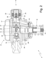
- the high-pressure pump 4 comprises a main body 12 that has a longitudinal axis 13 and defines, inside, a pumping chamber 14 with a cylindrical shape.
- a piston 15 is mounted so as to slide that, moving by reciprocating motion along the longitudinal axis 13, determines a cyclical variation of the volume of the pumping chamber 14.
- a smaller portion of the piston 15 is, on the one hand, coupled to a spring 16 that tends to push the piston 15 towards a maximum volume position of the pumping chamber 14 and, on the other hand, is coupled to a cam (not illustrated) that is rotated by an engine shaft of the internal combustion engine to cyclically move the piston 15 upwards, compressing the spring 16.
- the intake valve 18 is normally controlled under pressure and in the absence of external interventions, the intake valve 18 is closed when the pressure of the fuel in the pumping chamber 14 is greater than the pressure of the fuel in the intake duct 17 and is open when the pressure of the fuel in the pumping chamber 14 is less than the pressure of the fuel in the intake duct 17.
- the flow rate adjustment device 6 is mechanically coupled to the intake valve 18 to allow the control unit 7 to keep, when necessary, the intake valve 18 open during a pumping step of the piston 15 and, thus, to enable fuel to flow out of the pumping chamber 14 through the intake duct 17.
- a delivery duct 19 that is adjusted by a one-way delivery valve 20 (also called an "OCV - Outlet Closing Valve"), which is arranged at the pumping chamber 14 and only allows fuel to flow out of the pumping chamber 14, starts from a side wall of the pumping chamber 14 and from the opposite side to the intake duct 17.
- the delivery valve 20 is controlled under pressure and is open when the pressure of the fuel in the pumping chamber 14 is greater than the pressure of the fuel in the intake channel 19 and is closed when the pressure of the fuel in the pumping chamber 14 is less than the pressure of the fuel in the delivery channel 19.
- the intake duct 17 is adjusted by the intake valve 18 (arranged at the pumping chamber 14) and extends partially inside the main body 12.
- a damping device 21 (compensator), which is fixed to the main body 12 of the high-pressure pump 14 and has the function of reducing, in the low-pressure branch, the quantity of pulsations of the fuel flow rate and, thus, the quantity of oscillations of the fuel pressure, is arranged along the intake duct 17 (upstream of the intake valve 18).
- the flow rate adjustment device 6 comprises a control rod 22, which is coupled to the intake valve 18 and is movable between a passive position, in which it allows the intake valve 18 to close, and an active position, in which it does not allow the intake valve 18 to close.
- the flow rate adjustment device 6 also comprises an electromagnetic actuator 23, which is coupled to the control rod 22 to move the control rod 22 between the active position and the passive position.
- the electromagnetic actuator 23 comprises a spring 24, which holds the control rod 22 in the active position, and an electromagnet 25, which is designed to move the control rod 22 to the passive position magnetically attracting a ferromagnetic anchor 26 integral with the control rod 22 and, thus, overcoming the elastic force generated by the spring 24.
- the electromagnet 25 When the electromagnet 25 is excited, the control rod 22 is recalled to the passive position and the communication between the intake duct 7 and the pumping chamber 4 may be interrupted by the closure of the intake valve 18.
- the control rod 22 and the anchor 26 together form mobile equipment of the flow rate adjustment device 6 that is moved axially between the active position and the passive position under the control of the electromagnetic actuator 23.
- the intake valve 18 comprises a disc 27 that has a series of feeding holes that the fuel may flow through and a flexible sheet 28 with a circular shape (better illustrated in Figure 3 ) that rests on a base of the disc 27 closing the passage through the feeding holes.
- the intake valve 18 is normally controlled under pressure and in the absence of external interventions (i.e., of interventions of the flow rate adjustment device 6), the intake valve 18 is closed when the pressure of the fuel in the pumping chamber 14 is greater than the pressure of the fuel in the intake duct 17 and is open when the pressure of the fuel in the pumping chamber 14 is less than the pressure of the fuel in the intake duct 17.
- the sheet 28 when the fuel flows towards the pumping chamber 14, the sheet 28 is deformed moving away from the disc 27 under the thrust of the fuel allowing the passage of the fuel through the feeding holes; instead, when the fuel flows from the pumping chamber 14, the sheet 28 is crushed against the disc 27 sealing the feeding holes and, thus, preventing the passage of the fuel through the feeding holes.
- the control rod 22 In its active position, the control rod 22 centrally pushes on the sheet 28 preventing the sheet 28 from adhering to the disc 27 and, thus, preventing the sheet 28 from sealing the feeding holes; instead, in the passive position, the control rod 22 is relatively far from the sheet 28 allowing the sheet 28 to adhere to the disc 27 and, thus, allowing the sheet 28 to seal the feeding holes.
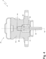
- a containing seat 29 is formed with a cylindrical shape having a greater diameter than the diameter of the pumping chamber 14 and houses a guide bushing 30 of the piston 15; the guide bushing 30 has, essentially, the function of guiding the axial, alternative sliding of the piston 15.
- the guide bushing 30 is made of a material with a suitable hardness and with a superficial finish so as to facilitate the axial sliding of the piston 15.
- the guide bushing 30 has a tubular shape and has, inside, a central through hole 31 that houses the piston 15 so as to slide; the central hole 31 of the guide bushing 30 (in which the piston 15 is arranged) and the piston 15 are processed with great precision so as to minimise the mechanical play (i.e. the distance) existing between the central hole 31 of the guide bushing 30 and the piston 15 (so as to limit, as much as possible, the leaking of fuel along the piston 15) without, in any case, completely eliminating this mechanical play (which is, obviously, indispensable for allowing the sliding of the piston 15 inside the guide bushing 30).
- the mechanical play i.e. the distance
- a sealing gasket 32 is interposed that has the function of further limiting the leaking of fuel along the piston 15.
- the sealing gasket 32 has a certain elasticity for being able to deform elastically (in particular for being radially compressed against the internal surface of the central hole 31 of the guide bushing 30).
- the sealing gasket 32 is preferably made with a material with a low friction coefficient; for example, the sealing gasket 32 could be made from a material based on PTFE (polytetrafluoroethylene, also commercially known with the name Teflon ® ) potentially loaded with glass or graphite.
- a one-way pressure relief valve also called a "PRV - Pressure Relieve Valve” that only allows fuel to flow inside the pumping chamber 14 through the delivery duct 19 and may be integrated together with the delivery valve 20.
- the function of the pressure relief valve is to allow a release of fuel in the event that the pressure of the fuel in the common rail 3 (i.e.
- the pressure relief valve is calibrated to automatically open when the jump in pressure at its ends is greater than a threshold value established in the design phase and, thus, to prevent the pressure of the fuel in the common rail 3 from exceeding the maximum value established in the design phase.
- the flow rate adjustment device 6 only acts on the intake valve 18 and does not have any effect on the delivery valve 20; in other words, the intake valve 18 is completely separate and independent of the delivery valve 20.
- control unit 7 detects when the internal combustion engine is stopped (switched off) and controls, immediately after (i.e. without any appreciable delay) the internal combustion engine has been stopped, the flow rate adjustment device 6 to allow the intake valve 18 to close (i.e., it activates the electromagnetic actuator 23 to move the control rod 22 from the normally active position assumed due to the thrust of the spring 24 to the passive position that allows the intake valve 18 to close).
- the control unit 7 preferably continues to control the flow rate adjustment device 6 to enable the intake valve 18 to close for a predetermined amount of time (generally lasting between 1 and 5 seconds). In other words, the control unit 7 keeps the electromagnetic actuator 23 active to keep the control rod 22 in the passive position that allows the intake valve 18 to close for the predetermined amount of time.
- the fuel pressure in the pumping chamber 14 becomes equal to the pressure of the fuel in the intake duct 17 and, thus, the pressure differential across the delivery valve 20 and the pressure relief valve becomes very high, causing the fuel to leak through the delivery valve 20 and the pressure relief valve (i.e. the high-pressure fuel that is found in the delivery duct 19 leaks through the delivery valve 20 and the pressure relief valve entering into the pumping chamber 14).
- the shutdown of the internal combustion engine i.e.
- the control unit 7 controls the flow rate adjustment device 6 to allow the intake valve 18 to close: when the pressure in the pumping chamber 14 increases (due to the high-pressure fuel that leaks through the delivery valve 20 and the pressure relief valve), the intake valve 18 spontaneously closes since the pressure of the fuel in the pumping chamber 14 has become greater than the pressure of the fuel in the intake duct 17. Once the intake valve 18 has closed (since the flow rate adjustment device 6 has allowed it to close), the pressure of the fuel in the pumping chamber 14 increases gradually (but increasingly slowly) due to the continuous (but increasingly reduced) leakage of fuel through the delivery valve 20 and the pressure relief valve.
- the pressure of the fuel in the pumping chamber 14 reaches a value so as to keep the intake valve 18 closed irrespective of the action of the flow rate adjustment device 6; in other words, the flow rate adjustment device 6 is able to prevent the intake valve 18 from closing when the pressure of the fuel in the pumping chamber 14 is only slightly (marginally) higher than the pressure of the fuel in the intake duct 17 but is not able to reopen the intake valve 18 when the pressure of the fuel in the pumping chamber 14 is basically higher than the pressure of the fuel in the intake duct 17.
- control unit 7 in the moment when the internal combustion engine has been stopped and without an appreciable delay, controls the flow rate adjustment device 6 to allow the intake valve 18 to close keeping, at the same time, the delivery valve 20 completely closed (i.e. without causing the delivery valve 20 to open, even partially), so as to minimise, from the moment when the internal combustion engine has been stopped and without an appreciable delay, both the fuel flowing out of the pumping chamber 14 through the intake valve 18 and the fuel flowing into the pumping chamber 14 through the delivery valve 20. In this way, the reduction of the pressure of the fuel in the delivery duct 19 and downstream of the pumping chamber 14 is minimised.
- control method described above has numerous advantages.
- the control method described above is able to significantly reduce the leaking of fuel both through the delivery valve 20 and through the pressure relief valve when the internal combustion engine is stopped (shut off).
- This result is obtained thanks to the fact that allowing the intake valve 18 to close when the internal combustion engine is stopped (shut off), the fuel that initially flows through the delivery valve 20 and through the pressure relief valve remains in the pumping chamber 14, increasing the pressure of the fuel inside the pumping chamber 14 and, thus, significantly reducing the pressure differential between the delivery valve 20 and the pressure relief valve.
- reducing (almost eliminating) the pressure differential between the delivery valve 20 and the pressure relief valve reduces (almost eliminates), as a consequence, the leaking of fuel through the delivery valve 20 and the pressure relief valve.
- control method described above is still more effective when the sealing gasket 32 is included that makes it possible to minimise the leaking of fuel from the pumping chamber 14 and through the play between the guide bushing 30 and the piston 15.
- control method described above can also be applied to an injection system 1 already marketed via a simple update to the software of the control method 7.
Landscapes
- Engineering & Computer Science (AREA)
- Chemical & Material Sciences (AREA)
- Combustion & Propulsion (AREA)
- Mechanical Engineering (AREA)
- General Engineering & Computer Science (AREA)
- Fuel-Injection Apparatus (AREA)
Claims (14)
- Procédé de commande d'un système d'injection de carburant (1) pour un moteur à combustion interne et doté d'une pompe à carburant (4) ; la pompe à carburant (4) comprend : une chambre de pompage (14) ; un piston (15) monté afin de coulisser à l'intérieur de la chambre de pompage (14) ; un conduit d'admission (17), qui se termine dans la chambre de pompage (14) et est prévu avec une valve d'admission (18) ; un conduit de refoulement (19), qui commence à partir de la chambre de pompage (14) et est prévu avec un clapet de refoulement (20) ; et un dispositif de réglage de débit (6) qui est couplé à la valve d'admission (18) et peut être commandé afin d'empêcher la fermeture de la valve d'admission (18) ou lui permettre de se fermer lorsqu'une pression de carburant à l'intérieur de la chambre de pompage (14) dépasse une pression de carburant dans le conduit d'admission (17) ;le procédé de commande comprend l'étape de détection lorsque le moteur à combustion interne est arrêté ;le procédé de commande est caractérisé en ce qu'il comprend l'étape supplémentaire de commande, au moment où le moteur à combustion interne a été arrêté et sans délai notable, du dispositif de réglage de débit (6) pour permettre à la valve d'admission (18) de se fermer, maintenant en même temps le clapet de refoulement (20) complètement fermé afin de minimiser, à partir du moment où le moteur à combustion interne a été arrêté et sans délai notable, à la fois le carburant sortant de la chambre de pompage (14) à travers la valve d'admission (18) et le carburant entrant dans la chambre de pompage (14) à travers le clapet de refoulement (20).
- Procédé de commande selon la revendication 1 et comprenant l'étape supplémentaire permettant de continuer la commande du dispositif de réglage de débit (6) pour permettre à la valve d'admission (18) de se fermer pendant un intervalle de temps prédéterminé.
- Procédé de commande selon la revendication 2, dans lequel l'intervalle de temps prédéterminé est dans la plage de 1 à 5 secondes.
- Procédé de commande selon la revendication 1, 2 ou 3, dans lequel le dispositif de réglage de débit (6) est contrôlé pour permettre à la valve d'admission (18) de se fermer immédiatement après que le moteur à combustion interne a été arrêté.
- Procédé de commande selon l'une des revendications 1 à 4, dans lequel le dispositif de réglage de débit (6) agit uniquement sur la valve d'admission (18) et n'a pas d'effet sur le clapet de refoulement (20).
- Procédé de commande selon l'une des revendications 1 à 5, dans lequel la valve d'admission (18) est complètement séparée et indépendante du clapet de refoulement (20).
- Procédé de commande selon l'une des revendications 1 à 6, dans lequel, au moment où le moteur à combustion interne a été arrêté et sans délai notable, le dispositif de réglage de débit (6) est commandé pour permettre à la valve d'admission (18) de se fermer, tout en maintenant en même temps le clapet de refoulement (20) complètement fermé afin de minimiser la réduction de pression du carburant dans le conduit de refoulement (19) et en aval de la chambre de pompage (14).
- Procédé de commande selon l'une des revendications 1 à 7, dans lequel :la pression du carburant dans la chambre de pompage (14), après que le moteur à combustion interne a été arrêté, augmente en raison du carburant à haute pression qui s'infiltre à travers le clapet de refoulement (20) et la valve d'admission (18) se ferme spontanément étant donné que la pression du carburant dans la chambre de pompage (14) est devenue plus importante que la pression du carburant dans le conduit d'admission (17) ;une fois que la valve d'admission (18) a été fermée, étant donné que le dispositif de réglage de débit (6) lui a permis de se fermer, la pression du carburant dans la chambre de pompe (14) augmente progressivement et de plus en plus lentement en raison de l'infiltration continue mais de plus en plus réduite de carburant à travers le clapet de refoulement (20) ;à un certain point, la pression du carburant dans la chambre de pompage (14) atteint une valeur qui lui permet de maintenir la valve d'admission (18) fermée indépendamment de l'action du dispositif de réglage de débit (6).
- Procédé de commande selon l'une des revendications 1 à 8, dans lequel le dispositif de réglage de débit (6) comprend une tige de commande (22) qui est couplée à la valve d'admission (18) et est mobile entre une position passive, dans laquelle elle permet à la valve d'admission (18) de se fermer, et une position active, dans laquelle elle ne permet pas à la valve d'admission (18) de se fermer.
- Procédé de commande selon la revendication 9, dans lequel le dispositif de réglage de débit (6) comprend un actionneur électromagnétique (23), qui est couplé à la tige de commande (22) pour déplacer la tige de commande (22) entre la position active et la position passive.
- Procédé de commande selon la revendication 10, dans lequel l'actionneur électromagnétique (23) comprend un ressort (24), qui maintient la tige de commande (22) dans la position active, et un électroaimant (25) qui est conçu pour déplacer la tige de commande (22) dans la position passive, venant à bout de la force élastique générée par le ressort (24).
- Procédé de commande selon la revendication 9, 10 ou 11, dans lequel la valve d'admission (18) comprend un disque (27) ayant une série de trous débouchants d'alimentation, à travers lesquels le carburant peut s'écouler et une feuille flexible (28) avec une forme circulaire, qui s'appuie contre une base du disque (27), fermant ainsi le passage à travers les trous d'alimentation et est couplée à la tige de commande (22) du dispositif de réglage de débit (6).
- Procédé de commande selon l'une des revendications 1 à 12, dans lequel la pompe à carburant (4) comprend :un siège de confinement (29) qui est défini dans le corps principal (12) au-dessous de la chambre de pompage (14) ;une douille de guidage (30) qui est logée dans le siège de confinement (29) et est prévue avec un trou central (31), où le piston (15) est agencé d'une manière coulissante ; etun joint d'étanchéité (32) intercalé entre le piston (15) et le trou central (31) de la douille de guidage (30).
- Procédé de commande selon l'une des revendications 1 à 13, dans lequel la pompe à carburant (4) comprend une soupape de décharge de pression unidirectionnelle, qui permet uniquement au carburant de s'écouler dans la chambre de pompage (14) à travers le conduit de refoulement (19).
Applications Claiming Priority (1)
| Application Number | Priority Date | Filing Date | Title |
|---|---|---|---|
| IT102022000020604A IT202200020604A1 (it) | 2022-10-06 | 2022-10-06 | Metodo di controllo di un sistema di iniezione di carburante |
Publications (2)
| Publication Number | Publication Date |
|---|---|
| EP4350139A1 EP4350139A1 (fr) | 2024-04-10 |
| EP4350139B1 true EP4350139B1 (fr) | 2025-01-22 |
Family
ID=84829670
Family Applications (1)
| Application Number | Title | Priority Date | Filing Date |
|---|---|---|---|
| EP23201578.4A Active EP4350139B1 (fr) | 2022-10-06 | 2023-10-04 | Procédé de commande d'un système d'injection de carburant |
Country Status (3)
| Country | Link |
|---|---|
| EP (1) | EP4350139B1 (fr) |
| CN (1) | CN117846800A (fr) |
| IT (1) | IT202200020604A1 (fr) |
Family Cites Families (5)
| Publication number | Priority date | Publication date | Assignee | Title |
|---|---|---|---|---|
| JP4353288B2 (ja) * | 2007-08-08 | 2009-10-28 | トヨタ自動車株式会社 | 燃料ポンプ |
| CN101982652A (zh) * | 2007-09-26 | 2011-03-02 | 株式会社电装 | 直喷式发动机的燃压控制器和高压泵控制器 |
| IT1396473B1 (it) | 2009-03-30 | 2012-12-14 | Magneti Marelli Spa | Pompa carburante con una valvola di massima pressione perfezionata per un sistema di iniezione diretta |
| US10683825B1 (en) * | 2018-12-04 | 2020-06-16 | Delphi Technologies Ip Limited | Fuel pump and inlet valve assembly thereof |
| IT202000017767A1 (it) * | 2020-07-22 | 2022-01-22 | Marelli Europe Spa | Pompa carburante per un sistema di iniezione diretta |
-
2022
- 2022-10-06 IT IT102022000020604A patent/IT202200020604A1/it unknown
-
2023
- 2023-10-04 EP EP23201578.4A patent/EP4350139B1/fr active Active
- 2023-10-07 CN CN202311280980.0A patent/CN117846800A/zh active Pending
Also Published As
| Publication number | Publication date |
|---|---|
| IT202200020604A1 (it) | 2024-04-06 |
| EP4350139A1 (fr) | 2024-04-10 |
| CN117846800A (zh) | 2024-04-09 |
Similar Documents
| Publication | Publication Date | Title |
|---|---|---|
| US8430081B2 (en) | Direct-injection system fuel pump with a maximum-pressure valve | |
| US8297941B2 (en) | Fuel pump | |
| JP4413260B2 (ja) | 高圧燃料ポンプ | |
| US20130302194A1 (en) | High-pressure pump | |
| US7997253B2 (en) | Method for controlling the overpressure in a fuel-supply system of a common-rail type | |
| CN101248265A (zh) | 带压电促动器预载的燃料喷射器 | |
| JP6829003B2 (ja) | 入口弁の良好な液圧シールを備える直接噴射システム用の燃料ポンプ | |
| US10267279B2 (en) | Control valve assembly and fuel injector incorporating a control valve assembly | |
| EP3088725B1 (fr) | Pompe à carburant destinée à un système d'injection directe avec une réduction de contrainte sur la bague de piston | |
| US10094346B1 (en) | Fuel pump with an improved maximum-pressure valve for a direct-injection system | |
| EP4350139B1 (fr) | Procédé de commande d'un système d'injection de carburant | |
| US6109542A (en) | Servo-controlled fuel injector with leakage limiting device | |
| US9512800B2 (en) | Valve assembly | |
| EP1783358B1 (fr) | Méthode de la fabrication d'une soupape d'injection de carburant | |
| CN102124203B (zh) | 用于供给内燃机动力燃料的装置 | |
| JP2010071266A (ja) | 高圧燃料供給装置 | |
| US6186122B1 (en) | Snap-lock retainer for a fuel injector | |
| CN107587964B (zh) | 适于直喷系统的具有改进的最大压力阀的燃料泵 | |
| BR102023020713A2 (pt) | Método para controlar um sistema de injeção de combustível | |
| US20090140187A1 (en) | Pressure control valve | |
| JPS59203864A (ja) | 内燃機関の燃料噴射装置 | |
| JP2011080443A (ja) | 吸入調量弁の制御装置および燃料噴射システム | |
| JP2009503349A (ja) | 内燃機関用燃料噴射装置 | |
| JP2005171811A (ja) | 増圧式燃料噴射装置 | |
| JP2015197095A (ja) | 燃料供給システム |
Legal Events
| Date | Code | Title | Description |
|---|---|---|---|
| PUAI | Public reference made under article 153(3) epc to a published international application that has entered the european phase |
Free format text: ORIGINAL CODE: 0009012 |
|
| STAA | Information on the status of an ep patent application or granted ep patent |
Free format text: STATUS: THE APPLICATION HAS BEEN PUBLISHED |
|
| STAA | Information on the status of an ep patent application or granted ep patent |
Free format text: STATUS: REQUEST FOR EXAMINATION WAS MADE |
|
| AK | Designated contracting states |
Kind code of ref document: A1 Designated state(s): AL AT BE BG CH CY CZ DE DK EE ES FI FR GB GR HR HU IE IS IT LI LT LU LV MC ME MK MT NL NO PL PT RO RS SE SI SK SM TR |
|
| 17P | Request for examination filed |
Effective date: 20240319 |
|
| RBV | Designated contracting states (corrected) |
Designated state(s): AL AT BE BG CH CY CZ DE DK EE ES FI FR GB GR HR HU IE IS IT LI LT LU LV MC ME MK MT NL NO PL PT RO RS SE SI SK SM TR |
|
| GRAP | Despatch of communication of intention to grant a patent |
Free format text: ORIGINAL CODE: EPIDOSNIGR1 |
|
| STAA | Information on the status of an ep patent application or granted ep patent |
Free format text: STATUS: GRANT OF PATENT IS INTENDED |
|
| INTG | Intention to grant announced |
Effective date: 20240830 |
|
| GRAS | Grant fee paid |
Free format text: ORIGINAL CODE: EPIDOSNIGR3 |
|
| GRAA | (expected) grant |
Free format text: ORIGINAL CODE: 0009210 |
|
| STAA | Information on the status of an ep patent application or granted ep patent |
Free format text: STATUS: THE PATENT HAS BEEN GRANTED |
|
| P01 | Opt-out of the competence of the unified patent court (upc) registered |
Free format text: CASE NUMBER: APP_62295/2024 Effective date: 20241121 |
|
| AK | Designated contracting states |
Kind code of ref document: B1 Designated state(s): AL AT BE BG CH CY CZ DE DK EE ES FI FR GB GR HR HU IE IS IT LI LT LU LV MC ME MK MT NL NO PL PT RO RS SE SI SK SM TR |
|
| REG | Reference to a national code |
Ref country code: GB Ref legal event code: FG4D |
|
| REG | Reference to a national code |
Ref country code: CH Ref legal event code: EP |
|
| REG | Reference to a national code |
Ref country code: IE Ref legal event code: FG4D |
|
| REG | Reference to a national code |
Ref country code: DE Ref legal event code: R096 Ref document number: 602023001767 Country of ref document: DE |
|
| REG | Reference to a national code |
Ref country code: NL Ref legal event code: MP Effective date: 20250122 |
|
| PG25 | Lapsed in a contracting state [announced via postgrant information from national office to epo] |
Ref country code: NL Free format text: LAPSE BECAUSE OF FAILURE TO SUBMIT A TRANSLATION OF THE DESCRIPTION OR TO PAY THE FEE WITHIN THE PRESCRIBED TIME-LIMIT Effective date: 20250122 |
|
| PG25 | Lapsed in a contracting state [announced via postgrant information from national office to epo] |
Ref country code: RS Free format text: LAPSE BECAUSE OF FAILURE TO SUBMIT A TRANSLATION OF THE DESCRIPTION OR TO PAY THE FEE WITHIN THE PRESCRIBED TIME-LIMIT Effective date: 20250422 |
|
| PG25 | Lapsed in a contracting state [announced via postgrant information from national office to epo] |
Ref country code: FI Free format text: LAPSE BECAUSE OF FAILURE TO SUBMIT A TRANSLATION OF THE DESCRIPTION OR TO PAY THE FEE WITHIN THE PRESCRIBED TIME-LIMIT Effective date: 20250122 |
|
| PG25 | Lapsed in a contracting state [announced via postgrant information from national office to epo] |
Ref country code: PL Free format text: LAPSE BECAUSE OF FAILURE TO SUBMIT A TRANSLATION OF THE DESCRIPTION OR TO PAY THE FEE WITHIN THE PRESCRIBED TIME-LIMIT Effective date: 20250122 |
|
| PG25 | Lapsed in a contracting state [announced via postgrant information from national office to epo] |
Ref country code: ES Free format text: LAPSE BECAUSE OF FAILURE TO SUBMIT A TRANSLATION OF THE DESCRIPTION OR TO PAY THE FEE WITHIN THE PRESCRIBED TIME-LIMIT Effective date: 20250122 |
|
| REG | Reference to a national code |
Ref country code: LT Ref legal event code: MG9D |
|
| PG25 | Lapsed in a contracting state [announced via postgrant information from national office to epo] |
Ref country code: IS Free format text: LAPSE BECAUSE OF FAILURE TO SUBMIT A TRANSLATION OF THE DESCRIPTION OR TO PAY THE FEE WITHIN THE PRESCRIBED TIME-LIMIT Effective date: 20250522 Ref country code: NO Free format text: LAPSE BECAUSE OF FAILURE TO SUBMIT A TRANSLATION OF THE DESCRIPTION OR TO PAY THE FEE WITHIN THE PRESCRIBED TIME-LIMIT Effective date: 20250422 |
|
| REG | Reference to a national code |
Ref country code: AT Ref legal event code: MK05 Ref document number: 1761633 Country of ref document: AT Kind code of ref document: T Effective date: 20250122 |
|
| PG25 | Lapsed in a contracting state [announced via postgrant information from national office to epo] |
Ref country code: HR Free format text: LAPSE BECAUSE OF FAILURE TO SUBMIT A TRANSLATION OF THE DESCRIPTION OR TO PAY THE FEE WITHIN THE PRESCRIBED TIME-LIMIT Effective date: 20250122 |
|
| PG25 | Lapsed in a contracting state [announced via postgrant information from national office to epo] |
Ref country code: LV Free format text: LAPSE BECAUSE OF FAILURE TO SUBMIT A TRANSLATION OF THE DESCRIPTION OR TO PAY THE FEE WITHIN THE PRESCRIBED TIME-LIMIT Effective date: 20250122 Ref country code: PT Free format text: LAPSE BECAUSE OF FAILURE TO SUBMIT A TRANSLATION OF THE DESCRIPTION OR TO PAY THE FEE WITHIN THE PRESCRIBED TIME-LIMIT Effective date: 20250522 |
|
| PG25 | Lapsed in a contracting state [announced via postgrant information from national office to epo] |
Ref country code: BG Free format text: LAPSE BECAUSE OF FAILURE TO SUBMIT A TRANSLATION OF THE DESCRIPTION OR TO PAY THE FEE WITHIN THE PRESCRIBED TIME-LIMIT Effective date: 20250122 Ref country code: GR Free format text: LAPSE BECAUSE OF FAILURE TO SUBMIT A TRANSLATION OF THE DESCRIPTION OR TO PAY THE FEE WITHIN THE PRESCRIBED TIME-LIMIT Effective date: 20250423 |
|
| PG25 | Lapsed in a contracting state [announced via postgrant information from national office to epo] |
Ref country code: AT Free format text: LAPSE BECAUSE OF FAILURE TO SUBMIT A TRANSLATION OF THE DESCRIPTION OR TO PAY THE FEE WITHIN THE PRESCRIBED TIME-LIMIT Effective date: 20250122 |
|
| PG25 | Lapsed in a contracting state [announced via postgrant information from national office to epo] |
Ref country code: SE Free format text: LAPSE BECAUSE OF FAILURE TO SUBMIT A TRANSLATION OF THE DESCRIPTION OR TO PAY THE FEE WITHIN THE PRESCRIBED TIME-LIMIT Effective date: 20250122 |
|
| PG25 | Lapsed in a contracting state [announced via postgrant information from national office to epo] |
Ref country code: SM Free format text: LAPSE BECAUSE OF FAILURE TO SUBMIT A TRANSLATION OF THE DESCRIPTION OR TO PAY THE FEE WITHIN THE PRESCRIBED TIME-LIMIT Effective date: 20250122 |
|
| PG25 | Lapsed in a contracting state [announced via postgrant information from national office to epo] |
Ref country code: DK Free format text: LAPSE BECAUSE OF FAILURE TO SUBMIT A TRANSLATION OF THE DESCRIPTION OR TO PAY THE FEE WITHIN THE PRESCRIBED TIME-LIMIT Effective date: 20250122 |
|
| PGFP | Annual fee paid to national office [announced via postgrant information from national office to epo] |
Ref country code: FR Payment date: 20250924 Year of fee payment: 3 |
|
| PG25 | Lapsed in a contracting state [announced via postgrant information from national office to epo] |
Ref country code: EE Free format text: LAPSE BECAUSE OF FAILURE TO SUBMIT A TRANSLATION OF THE DESCRIPTION OR TO PAY THE FEE WITHIN THE PRESCRIBED TIME-LIMIT Effective date: 20250122 Ref country code: CZ Free format text: LAPSE BECAUSE OF FAILURE TO SUBMIT A TRANSLATION OF THE DESCRIPTION OR TO PAY THE FEE WITHIN THE PRESCRIBED TIME-LIMIT Effective date: 20250122 |
|
| REG | Reference to a national code |
Ref country code: DE Ref legal event code: R097 Ref document number: 602023001767 Country of ref document: DE |
|
| PG25 | Lapsed in a contracting state [announced via postgrant information from national office to epo] |
Ref country code: RO Free format text: LAPSE BECAUSE OF FAILURE TO SUBMIT A TRANSLATION OF THE DESCRIPTION OR TO PAY THE FEE WITHIN THE PRESCRIBED TIME-LIMIT Effective date: 20250122 |
|
| PG25 | Lapsed in a contracting state [announced via postgrant information from national office to epo] |
Ref country code: SK Free format text: LAPSE BECAUSE OF FAILURE TO SUBMIT A TRANSLATION OF THE DESCRIPTION OR TO PAY THE FEE WITHIN THE PRESCRIBED TIME-LIMIT Effective date: 20250122 |
|
| PLBE | No opposition filed within time limit |
Free format text: ORIGINAL CODE: 0009261 |
|
| STAA | Information on the status of an ep patent application or granted ep patent |
Free format text: STATUS: NO OPPOSITION FILED WITHIN TIME LIMIT |
|
| 26N | No opposition filed |
Effective date: 20251023 |
|
| PGFP | Annual fee paid to national office [announced via postgrant information from national office to epo] |
Ref country code: DE Payment date: 20250923 Year of fee payment: 3 |
|
| PGFP | Annual fee paid to national office [announced via postgrant information from national office to epo] |
Ref country code: IT Payment date: 20251031 Year of fee payment: 3 |