EP4350167A1 - Cylindre d'estampage à gaz - Google Patents
Cylindre d'estampage à gaz Download PDFInfo
- Publication number
- EP4350167A1 EP4350167A1 EP21734878.8A EP21734878A EP4350167A1 EP 4350167 A1 EP4350167 A1 EP 4350167A1 EP 21734878 A EP21734878 A EP 21734878A EP 4350167 A1 EP4350167 A1 EP 4350167A1
- Authority
- EP
- European Patent Office
- Prior art keywords
- piston
- gas
- cylinder
- chamber
- recess
- Prior art date
- Legal status (The legal status is an assumption and is not a legal conclusion. Google has not performed a legal analysis and makes no representation as to the accuracy of the status listed.)
- Granted
Links
Images


Classifications
-
- F—MECHANICAL ENGINEERING; LIGHTING; HEATING; WEAPONS; BLASTING
- F16—ENGINEERING ELEMENTS AND UNITS; GENERAL MEASURES FOR PRODUCING AND MAINTAINING EFFECTIVE FUNCTIONING OF MACHINES OR INSTALLATIONS; THERMAL INSULATION IN GENERAL
- F16F—SPRINGS; SHOCK-ABSORBERS; MEANS FOR DAMPING VIBRATION
- F16F9/00—Springs, vibration-dampers, shock-absorbers, or similarly-constructed movement-dampers using a fluid or the equivalent as damping medium
- F16F9/32—Details
- F16F9/34—Special valve constructions; Shape or construction of throttling passages
- F16F9/346—Throttling passages in the form of slots arranged in cylinder walls
-
- F—MECHANICAL ENGINEERING; LIGHTING; HEATING; WEAPONS; BLASTING
- F16—ENGINEERING ELEMENTS AND UNITS; GENERAL MEASURES FOR PRODUCING AND MAINTAINING EFFECTIVE FUNCTIONING OF MACHINES OR INSTALLATIONS; THERMAL INSULATION IN GENERAL
- F16F—SPRINGS; SHOCK-ABSORBERS; MEANS FOR DAMPING VIBRATION
- F16F9/00—Springs, vibration-dampers, shock-absorbers, or similarly-constructed movement-dampers using a fluid or the equivalent as damping medium
- F16F9/32—Details
- F16F9/48—Arrangements for providing different damping effects at different parts of the stroke
-
- F—MECHANICAL ENGINEERING; LIGHTING; HEATING; WEAPONS; BLASTING
- F16—ENGINEERING ELEMENTS AND UNITS; GENERAL MEASURES FOR PRODUCING AND MAINTAINING EFFECTIVE FUNCTIONING OF MACHINES OR INSTALLATIONS; THERMAL INSULATION IN GENERAL
- F16F—SPRINGS; SHOCK-ABSORBERS; MEANS FOR DAMPING VIBRATION
- F16F9/00—Springs, vibration-dampers, shock-absorbers, or similarly-constructed movement-dampers using a fluid or the equivalent as damping medium
- F16F9/02—Springs, vibration-dampers, shock-absorbers, or similarly-constructed movement-dampers using a fluid or the equivalent as damping medium using gas only or vacuum
- F16F9/0209—Telescopic
- F16F9/0218—Mono-tubular units
Definitions
- the present invention relates to gas stamping cylinders which require high forces.
- gas cylinders are widely known for different applications. For example, their use in vehicle doors for supporting the weight of said doors or for lifting them is known. Cylinders of this type of require withstanding small forces, so they are generally simple.
- Cylinders of this type are stamping cylinders (due to the high forces they require) and are more complex than those mentioned in the preceding paragraph, and although their general basic concept may be similar (a piston that is moveable and compresses or decompresses a chamber with its movement), they are constructively very different and have very little in common with the aforementioned cylinders.
- a stamping damper comprised a spring which was compressed by the action of the press, and when the die returned to its initial position, it was decompressed. The greater the force that the press had to exert was, the larger the dimensions of the spring were. This implied a limitation in the maximum force of presses, given that, among other things, they required large spaces and could furthermore be expensive.
- stamping cylinders by way of dampers started to be used. These stamping cylinders comprise a moveable piston, a first chamber with a compressible gas, and a second chamber.
- the second chamber can comprise nil volume in the piston rest position which increases as said piston descends. Both chambers were cut off from one another, and gas could not be evacuated from the first chamber to the second chamber.
- Stamping cylinders of this type are commonly known as single-chamber gas stamping cylinders.
- the use of gas stamping cylinders allowed the force of the press compared with the spring to be increased, given that for one and the same force as the force allowed by a spring, a gas stamping cylinder requires smaller dimensions.
- gas stamping cylinders of this type single-chamber gas stamping cylinders
- the pressure of the gas in the first chamber of said cylinder increases. This pressure is the force which the cylinder exerts against the movement of the die.
- the piston also comprises a rod having a specific diameter which is pushed by the lower die (directly or indirectly, in which case the part to be stamped would be located between both).
- the piston continues to descend, pushed by the die, and the pressure in the first chamber increases, which implies a risk if the stamping cylinder fails for any reason or if the gas exceeds a maximum safety pressure for which this cylinder was designed.
- the piston is also pushed upwards by the pressure present in the first chamber, and this pressure causes the upward force of the piston to be high (since, as occurs in the downward movement of the piston, it depends on the surface of the base facing the first chamber), and it causes the piston to move upwards together with the upper die. Therefore, in addition to having a high pressure in the first chamber during the downward movement, stamping cylinders of this type cannot be used satisfactorily in some stamping applications, given that due to this high upward force, they could affect the recently stamped part.
- Gas stamping cylinders with solutions delaying the upward movement of the piston are also described in EP2735759A1 , EP1186795A2 , and EP1074759A2 , for example.
- the first both chambers are communicated through a path having a limited diameter. This limitation causes the transfer of gas from the second chamber to the first chamber to be slow, such that the piston moves upwards with a speed lower than the descending speed. The upward force of the piston is thereby delayed or slowed.
- the gas stamping cylinder has to exert a specific force against the movement of the upper die during the descent of said upper die, so cylinders of this type have the drawback that the final force exerted by the cylinder by far exceeds the specific force, given that the pressure in the first chamber increases as the piston descends.
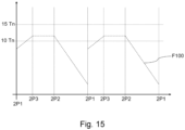
- Figure 1 shows a development F1 of the force exerted by the cylinder in these cases (without considering a delay) from the piston rest position Pr to the compression position Pc, and from said compression position Pc to said rest position Pr, for a cylinder for which a specific force of 10 tons (10 Tn) is required.
- the cylinder exerts from the start (rest position Pr) a force close to the specific force (potentially the same), and this force F1 continues to increase until the piston reaches the compression position Pc. The piston then retreats to its rest position Pr, with the force dropping to the initial value.
- WO2020128133A1 discloses a gas stamping cylinder configured for also overcoming this drawback.
- the cylinder disclosed in this document comprises a central axis, a main body defining an inner cavity, and a piston suitable for moving between a rest position and a compression position.
- the piston comprises a base and a main rod extending from the base.
- the cylinder comprises a release path for communicating the two chambers, and a release device blocking said path in a blocking position and configured for coming out of said position when the pressure in the first chamber is equal to or greater than a predetermined threshold value.
- the release device comprises a spring housed in the piston and in the release path, which is tared based on the specific force required in each case.
- Figure 1 also depicts the development of the force F2 exerted by said cylinder for the same case as the one described above, such that both forces F1 and F2 can be compared. Furthermore, it should be indicated that at least by having a lower maximum force, the dimensions of the cylinder are also smaller.
- the object of the invention is to provide a gas stamping cylinder, as defined in the claims.
- the gas stamping cylinder of the invention is configured for being used in stamping presses and comprises a central axis, a main body defining a cylindrical inner cavity, and a piston suitable for moving in the inner cavity in a first longitudinal direction and a second longitudinal direction opposite the first longitudinal direction, between a rest position and a compression position.
- the piston comprises a base and a main rod extending axially from the base, and said main rod comprises an end protruding from the main body at least with the piston in the rest position.
- the cylinder comprises a gaseous fluid at least in the gas chamber.
- the piston comprises at least one contact zone configured for sliding over a contact surface of the cylinder during its movement, and a closure element arranged in said contact zone and configured for impeding the passage of gaseous fluid from the gas chamber between said contact zone of the piston and said contact surface.
- the contact surface comprises at least one recess downstream of the piston, with said piston in the rest position, such that when the contact zone of the piston coincides during its movement with said recess, gaseous fluid present in the gas chamber is evacuated from said gas chamber through said recess.
- the closure element stops cooperating with the contact surface in the recess position, such that a path for the passage of gas between said contact zone of the piston and said contact surface (through the recess) opens up.
- the gaseous fluid present in the gas chamber is compacted, increasing its pressure.
- the proposed stamping cylinder as a result of the recess, during said movement of the piston there is at least one moment in which a path is enabled for the gaseous fluid to be evacuated from the gas chamber, with part of the pressure present in said gas chamber in that moment thus being released, and the maximum value which the pressure of said gaseous fluid may reach thus being limited. This allows a required or desired maximum value to be pre-set, and by suitably adjusting the position of the recess, it is possible that said stamping cylinder will exceed said maximum value.
- the cylinder 100 of the invention is a gas stamping cylinder, which implies that it is configured for the stamping applications where the cylinder is required to offer high forces, such as in stamping presses.
- the cylinder 100 can thus be configured for stamping presses.
- Figure 2 shows an embodiment of the cylinder 100.
- the cylinder 100 comprises a central axis 100.1, a main body 1 defining a cylindrical inner cavity delimited by an inner surface 1.3, and a piston 2 suitable for moving in the inner cavity between a rest position 2P1 (see Figure 3 ) and a compression position 2P2 (see Figure 4 ).
- the piston 2 moves in a first longitudinal direction 1L (the piston 2 descends), whereas for moving to the rest position 2P1, said piston 2 moves in a second longitudinal direction 2L opposite the first longitudinal direction 1L (the piston rises or moves upwards).
- Both longitudinal directions 1L and 2L are linear directions.
- the piston 2 comprises a base 2.0 and a main rod 2.1 extending axially from the base 2.0.
- the main rod 2.1 has an end protruding from the main body 1 of the cylinder 100 at least with the piston 2 in the rest position 2P1, at a part of said main body 1 opposite a lower base 1.0 of said main body 1.
- the main rod 2.1 is thus actuated on said end protruding by an actuation element not depicted in the figures (an upper die of a press for example) in order to move it to the compression position 2P2, and said cylinder 100 offers a force opposing said movement.
- the cylinder 100 comprises, in the cylindrical inner cavity defined in the main body 1 and below the base 2.0 of the piston 2, a gas chamber 1.1 with a gaseous fluid therein.
- the cylinder 100 further comprises an additional chamber 1.2 above said base 2.0, which can comprise nil volume with the piston 2 in the rest position 2P1 (see example of Figure 3 ), but the volume of which increases as the piston descends to its compression position 2P2.
- the piston 2 comprises at least one contact zone 2.91, preferably at the base 2.0, configured for sliding over a contact surface 3 of the cylinder 100 during its movement
- the cylinder 100 comprises a closure element 8.1 arranged in said contact zone 2.91 and configured for cooperating with the contact surface 3 and impeding, with said cooperation, the passage of gaseous fluid of the gas chamber 1.1 between said contact zone 2.91 of the piston 2 and said contact surface 3.
- the volume of the gas chamber 1.1 thereby decreases and the gaseous fluid present in said gas chamber 1.1 is compressed, the force exerted by the cylinder 100 against said movement being increased.
- the gas chamber 1.1 is delimited by the base 2.0 of the piston 2 and the part of the inner surface 1.3 of said main body 1 below the base 2.0, so said cooperation impedes this evacuation of gas.
- the closure element 8.1 can be an O-ring.
- the contact surface 3 comprises at least one recess 3.0 below the piston 2, with said piston 2 in the rest position 2P1, said recess 3.0 comprising a specific axial length 3W, axial being understood to mean a length extending in a direction parallel to the central axis 100.1 of the cylinder 100. Therefore, when the contact zone 2.91 of the piston 2 at least partially coincides with said recess 3.0 (position 2P3), and at least during the movement of said piston 2 in the first longitudinal direction 1L, the closure element 8.1 stops cooperating with the contact surface 3 and a space is opened between said contact zone 2.91 and said contact surface 3 through which gaseous fluid present in the gas chamber 1.1 is evacuated from said gas chamber 1.1.
- the position of the recess 3.0 will be selected based on the force requirements of the manufacturer of the cylinder 100 and/or of the end customer of said cylinder 100, i.e., it will be placed closer to or farther away from the piston 2, with said piston 2 in the rest position 2P1, based on said requirements (which may include, for example, the desired force for the cylinder 100 and/or the desired stroke for the piston 2).
- the axial length 3W of the recess 3.0 is greater than an axial length 2W of the contact zone 2.91 of the piston 2. This ensures that the contact zone 2.91 and/or the closure element 8.1 does not completely cover the recess 3.0 in some position of the piston 2, ensuring that with the piston 2 in said position, a passage for the gaseous fluid present in the gas chamber 1.1 (passage between the contact zone 2.9 and the contact surface 3, as a result of the recess 3.0) is enabled.
- the recess 3.0 does not span the entire perimeter around the central axis 100.1.
- the base 2.0 is always allowed to have some part resting against the main body 1 (against the contact surface 3), preventing the risk of the closure element 8.1 from losing its position, for example.
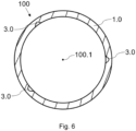
- the contact surface 3 can comprise a plurality of recesses 3.0 distributed in the same transverse plane, as depicted in the example of Figure 6 , which facilitates the evacuation of gas as a plurality of paths for the evacuation thereof (one per recess 3.0) have been enabled, without negatively affecting the stability of the piston 2 and of the closure element 8.1.
- three recesses 3.0 are depicted in the same transverse plane, but the contact surface 3 might have a different number of recesses 3.0.
- the contact surface 3 comprises a plurality of recesses 3.0 distributed in the same transverse plane
- said recesses 3.0 can be distributed uniformly around the central axis 100.1 of the cylinder 100. This would allow the gaseous fluid to be evacuated in a uniform manner around said central axis 100.1, preventing some parts of the cylinder 100 from being more affected than others and thus preventing unnecessary deteriorations of said cylinder 100 for this reason.
- the recess 3.0 could be circular, i.e., it could span the entire perimeter around the central axis 100.1, and would have in this case the central axis 100.1 of the cylinder 100 as the center. This would allow the area through which the gaseous fluid can be evacuated from the gas chamber 1.1 to be increased, which would facilitate the limitation of the force of the cylinder 100 against the movement of the actuation element which pushes the piston 2 in the first longitudinal direction 1L, without needing to increase in excess the axial length 3W of the recess 3.0.
- the base 2.0 of said piston 2 would not rest against the main body 1 and it runs the risk of the closure element 8.1 becoming detached from the base 2.0 and/or of the piston 2 becoming unstable.
- the contact surface 3 of the cylinder 100 can further comprise a plurality of recesses 3.0 distributed axially with respect to the central axis 100.1 of the cylinder 100, both when a recess 3.0 does not span the entire perimeter angular (see the embodiment of Figures 3 to 5 ) and when it does (see Figure 8 ). That is, the contact surface 3 can comprise recesses 3.0 at different heights with respect to a lower base 1.0 of the main body 1 (or in different transverse planes).
- the contact surface 3 may comprise a plurality of recesses 3.0, in the case of recesses 3.0 that do not span the entire perimeter around the central axis 100.1 of the cylinder 100. Therefore, if the piston 2 continues to move in the first longitudinal direction 1L after the first recess 3.0 and the contact zone 2.91 coincide and after a path for the passage of the gaseous fluid is closed, during said movement said contact zone 2.91 will coincide with a new recess 3.0 (the one located in the lowest position), with a new path for the passage of gaseous fluid opening up and the increase in force offered by the cylinder 100 against said movement of the piston 2 being impeded despite said movement additional of said piston 2.
- the arrangement of the recesses 3.0 at different heights is previously selected based on the force requirements of the manufacturer of the cylinder 100 and/or of the end customer of said cylinder 100.
- the piston 2 comprises two contact zones 2.91 and 2.92 axially separated from one another (in other embodiments it could have more contact zones), an auxiliary chamber 2.8 being defined between both contact zones 2.91 and 2.92 (within the cylindrical inner cavity defined in the main body 1).
- the contact surface 3 preferably comprises recesses 3.0 at different heights with respect to the lower base 1.0 of the main body 1 of the cylinder 100.
- Each contact zone 2.91 and 2.92 comprises an associated closure element 8.1 and 8.2, with the function previously described.
- the closure element 8.2 can be, for example, an O-ring (like closure element 8.1).
- the axial distance between two contiguous recesses 3.0 of the contact surface 3 of the cylinder 100 is other than the axial distance between the two contact zones 2.91 and 2.92 of the piston 2 (other than the distance between the two sealing elements 8.1 and 8.2), preferably being greater than same, such that both contact zones 2.91 and 2.92 do not simultaneously coincide with two recesses 3.0, so that two paths for the passage of gaseous fluids do not open up simultaneously.
- a path for the passage opens up between the contact zone 2.91 arranged in the lowest position and the contact surface 3, this allows the gaseous fluid that is evacuated from the gas chamber 1.1 to be stored in the auxiliary chamber 2.8 ( Figure 9 ).
- the contact surface 3 can comprise recesses 3.0 at different heights with respect to the lower base 1.0 of the main body 1. These recesses 3.0 may or may not span the entire perimeter around the central axis 100.1 of said cylinder 100.
- the contact surface 3 preferably comprises a recess 3.0 arranged such that, with the piston 2 in the rest position 2P1, the contact zone 2.91 that is closest to the lower base 1.0 of the main body 1 (the contact zone 2.91 which his in the lowest position) coincides with said recess 3.0, as shown in the embodiment depicted in Figure 12 .
- the contact surface 3 comprises a plurality of recesses 3.0 at different heights with respect to the lower base 1.0, and said recess 3.0 is the recess 3.0 farthest away from said lower base 1.0.
- the contact surface 3 is the inner surface 1.3 of the main body 1 delimiting the cylindrical inner cavity. In this manner, machining the recesses 3.0 (or the recess 3.0) in said inner surface 1.3 is enough to obtain the described advantages.
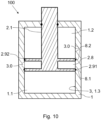
- the cylinder 100 comprises a longitudinal rod 4 attached to the lower base 1.0 of the main body 1 and comprises a longitudinal axis 4.1 parallel to the central axis 100.1 of the cylinder 100, or coinciding with said central axis 100.1, and an outer surface 4.2.
- Said outer surface 4.2 is the contact surface 3 of said cylinder 100.
- the recess 3.0 (or recesses 3.0) is in said outer surface 4.2, preferably facing the inner surface 1.3 of the main body 1 of the cylinder 100.
- Having a contact surface 3 in an additional part (the longitudinal rod 4) allows the machining of the inner surface 1.3 of the main body 1 in order to obtain the recesses 3.0 to be dispensed with, and that is particularly advantageous for those cylinders 100 in which said inner surface 1.3 cannot be readily accessed.
- the recesses 3.0 (or recess 3.0) of the longitudinal rod 4 can be made before attaching the longitudinal rod 4 to the main body 1 of the cylinder, so manufacturing a cylinder 100 in that way is simple, even if it requires at least one additional element (the longitudinal rod 4) to be used.
- the piston 2 can comprise a housing 2.2 open at its front part, for at least partially housing the longitudinal rod 4.
- the presence of the longitudinal rod 4 therefore does not affect the movement of the piston 2.
- the longitudinal rod 4 is partially housed in the housing 2.2 of the piston 2 when said piston 2 is in the rest position 2P1, such that it is ensured that the piston 2 does not collide with said longitudinal rod 4 when it starts to move in the first longitudinal direction 1L from the rest position 2P1.
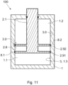
- the piston 2 can comprise a through hole 2.7 communicating the housing 2.2 with the additional chamber 1.2, such that when the region of actuation 2.91 coincides with a recess 3.0, the gaseous fluid that is evacuated from the gas chamber 1.1 through said recess 3.0 reaches said additional chamber 1.2 through said through hole 2.7. This ensures the evacuation of said gaseous fluid from said gas chamber 1.1 in a simple manner.
- Said through hole 2.7 is preferably at the base 2.0 of the piston 2, as shown in Figures 13 and 14 , although it could also be in the main rod 2.1.
- the piston 2 comprises two contact zones 2.91 and 2.92 and an auxiliary chamber 2.8 between both contact zones 2.91 and 2.92, with the through hole 2.7 being associated with the contact zone 2.91 or 2.92 farthest away from the gas chamber 1.1 and configured for communicating the auxiliary chamber 2.8 with the additional chamber 1.2.
- the other contact zone 2.91 or 2.92 will also have an axial length 2W less than the axial length 3W of the recess 3.0, as described above, to allow the gas that is evacuated from the gas chamber 1.1 to reach the auxiliary chamber 2.8.
- the above-described advantages of having an auxiliary chamber 2.8 are also obtained in these embodiments.
- the piston 2 can comprise, as shown in the embodiments of Figures 2 to 4 , at least one path 2.6 communicating the gas chamber 1.1 with the additional chamber 1.2, the cylinder 100 comprising a blocking element 2.5 housed in said path 2.6 and configured for enabling the passage of fluid through said path 2.6 only from the additional chamber 1.2 to the gas chamber 1.1.
- the upward movement of the piston 2 to its rest position 2P1 is thereby facilitated once the actuation element (the die of a press, for example) stops acting on said piston 2.
- the cylinder can comprise a path 2.6 and a blocking element 2.5 associated with each contact zone 2.91 and 2.92, as shown in Figure 12 , although it may comprise a single path communicating the gas chamber 1.1 with the additional chamber 1.2.
- the path 2.6 of a contact zone 2.01 serves to communicate the gas chamber 1.1 with the auxiliary chamber 2.8
- the other path 2.6 serves to communicate said auxiliary chamber 2.8 with the additional chamber 1.2.
- Each blocking element 2.5 is configured for allowing the communication of gas from the upper chamber to the lower chamber (from the auxiliary chamber 2.8 to the gas chamber 1.1 in one case, and from the additional chamber 1.2 to the auxiliary chamber 2.8 in the other case).
Landscapes
- Engineering & Computer Science (AREA)
- General Engineering & Computer Science (AREA)
- Mechanical Engineering (AREA)
- Pistons, Piston Rings, And Cylinders (AREA)
- Fluid-Damping Devices (AREA)
Applications Claiming Priority (1)
| Application Number | Priority Date | Filing Date | Title |
|---|---|---|---|
| PCT/ES2021/070372 WO2022248743A1 (fr) | 2021-05-25 | 2021-05-25 | Cylindre d'estampage à gaz |
Publications (3)
| Publication Number | Publication Date |
|---|---|
| EP4350167A1 true EP4350167A1 (fr) | 2024-04-10 |
| EP4350167C0 EP4350167C0 (fr) | 2025-11-26 |
| EP4350167B1 EP4350167B1 (fr) | 2025-11-26 |
Family
ID=76624060
Family Applications (1)
| Application Number | Title | Priority Date | Filing Date |
|---|---|---|---|
| EP21734878.8A Active EP4350167B1 (fr) | 2021-05-25 | 2021-05-25 | Cylindre d'estampage à gaz |
Country Status (3)
| Country | Link |
|---|---|
| EP (1) | EP4350167B1 (fr) |
| ES (1) | ES3061367T3 (fr) |
| WO (1) | WO2022248743A1 (fr) |
Families Citing this family (1)
| Publication number | Priority date | Publication date | Assignee | Title |
|---|---|---|---|---|
| KR102867981B1 (ko) * | 2023-05-18 | 2025-10-14 | 효성중공업 주식회사 | 대시포트 |
Family Cites Families (8)
| Publication number | Priority date | Publication date | Assignee | Title |
|---|---|---|---|---|
| WO1997008476A1 (fr) | 1995-08-29 | 1997-03-06 | Diebolt International, Inc. | Ressort a gaz a course de retour temporisee |
| US6170809B1 (en) | 1999-08-05 | 2001-01-09 | Diebolt International, Inc. | Delay return gas spring |
| DE10024499B4 (de) * | 2000-05-21 | 2004-08-26 | Forschungsgesellschaft Umformtechnik Mbh | Gasdruckzylinder, insbesondere in der Art einer Stickstofffeder |
| EP1186795B1 (fr) | 2000-08-29 | 2006-01-11 | Bordignon Silvano S.p.A. | Ressort pneumatique à contrôle du retour élastique et appareil comportant un tel ressort |
| EP2735759B1 (fr) | 2011-07-22 | 2018-04-11 | Azol-gas, S. L. | Ressort à gaz à retour ralenti |
| ES2684688T3 (es) * | 2012-03-01 | 2018-10-04 | Special Springs S.R.L. | Actuador de cilindro de gas con dispositivo de seguridad de sobrerrecorrido |
| JP6595242B2 (ja) * | 2014-07-31 | 2019-10-23 | スペシャル・スプリングス・ソシエタ・ア・レスポンサビリタ・リミタータ | ガス作動型ばね |
| ES2768449A1 (es) | 2018-12-20 | 2020-06-22 | Bikkean Global Services S L U | Cilindro de gas |
-
2021
- 2021-05-25 EP EP21734878.8A patent/EP4350167B1/fr active Active
- 2021-05-25 WO PCT/ES2021/070372 patent/WO2022248743A1/fr not_active Ceased
- 2021-05-25 ES ES21734878T patent/ES3061367T3/es active Active
Also Published As
| Publication number | Publication date |
|---|---|
| WO2022248743A1 (fr) | 2022-12-01 |
| ES3061367T3 (en) | 2026-04-01 |
| EP4350167C0 (fr) | 2025-11-26 |
| EP4350167B1 (fr) | 2025-11-26 |
Similar Documents
| Publication | Publication Date | Title |
|---|---|---|
| ES2689334T3 (es) | Dispositivo amortiguador hidráulico | |
| EP4350167A1 (fr) | Cylindre d'estampage à gaz | |
| KR102012982B1 (ko) | 실린더 장치 | |
| CA2902779A1 (fr) | Soupape de surete du type a bouchon fusible | |
| US20030000589A1 (en) | Hydropneumatic accumulator | |
| CN108457927B (zh) | 具有用于活塞杆的不受控返回的安全设备的气缸致动器 | |
| US20220178456A1 (en) | Relief valve | |
| EP1680576B1 (fr) | Compresseur alternatif a siege de soupape de surface accrue | |
| EP0247807B1 (fr) | Clapet de détente avec contrôle de surpression pour réservoir de fluide | |
| EP3184847B1 (fr) | Actionneur à vérin à gaz avec dispositif de sécurité | |
| EP2735759B1 (fr) | Ressort à gaz à retour ralenti | |
| JPH09303463A (ja) | ガス封入緩衝部材 | |
| US2941523A (en) | Hydraulic tappet | |
| EP3983717B1 (fr) | Soupape de décompression | |
| KR100592809B1 (ko) | 안전밸브 | |
| JP6514573B2 (ja) | 緩衝器 | |
| EP3819519A1 (fr) | Ressort à gaz de butée contrôlée | |
| EP2470316B1 (fr) | Ressort pneumatique pour dispositif de fermeture coulissant refractraire | |
| EP4075010A1 (fr) | Cylindre séparateur de poinçon et pour presses | |
| EP1892436B1 (fr) | Structure de soupape pour amortisseur | |
| CN214367997U (zh) | 一种流体低压释放装置 | |
| CN112268077A (zh) | 一种带低压释放的amt离合机电装置 | |
| JP2008248927A (ja) | リリーフバルブ | |
| EP3012480B1 (fr) | Ressort à gaz à décompression contrôlée | |
| CN109058215B (zh) | 一种插装式平衡阀 |
Legal Events
| Date | Code | Title | Description |
|---|---|---|---|
| STAA | Information on the status of an ep patent application or granted ep patent |
Free format text: STATUS: UNKNOWN |
|
| STAA | Information on the status of an ep patent application or granted ep patent |
Free format text: STATUS: THE INTERNATIONAL PUBLICATION HAS BEEN MADE |
|
| PUAI | Public reference made under article 153(3) epc to a published international application that has entered the european phase |
Free format text: ORIGINAL CODE: 0009012 |
|
| STAA | Information on the status of an ep patent application or granted ep patent |
Free format text: STATUS: REQUEST FOR EXAMINATION WAS MADE |
|
| 17P | Request for examination filed |
Effective date: 20240102 |
|
| AK | Designated contracting states |
Kind code of ref document: A1 Designated state(s): AL AT BE BG CH CY CZ DE DK EE ES FI FR GB GR HR HU IE IS IT LI LT LU LV MC MK MT NL NO PL PT RO RS SE SI SK SM TR |
|
| DAV | Request for validation of the european patent (deleted) | ||
| DAX | Request for extension of the european patent (deleted) | ||
| GRAP | Despatch of communication of intention to grant a patent |
Free format text: ORIGINAL CODE: EPIDOSNIGR1 |
|
| STAA | Information on the status of an ep patent application or granted ep patent |
Free format text: STATUS: GRANT OF PATENT IS INTENDED |
|
| INTG | Intention to grant announced |
Effective date: 20250626 |
|
| GRAS | Grant fee paid |
Free format text: ORIGINAL CODE: EPIDOSNIGR3 |
|
| GRAA | (expected) grant |
Free format text: ORIGINAL CODE: 0009210 |
|
| STAA | Information on the status of an ep patent application or granted ep patent |
Free format text: STATUS: THE PATENT HAS BEEN GRANTED |
|
| AK | Designated contracting states |
Kind code of ref document: B1 Designated state(s): AL AT BE BG CH CY CZ DE DK EE ES FI FR GB GR HR HU IE IS IT LI LT LU LV MC MK MT NL NO PL PT RO RS SE SI SK SM TR |
|
| REG | Reference to a national code |
Ref country code: CH Ref legal event code: F10 Free format text: ST27 STATUS EVENT CODE: U-0-0-F10-F00 (AS PROVIDED BY THE NATIONAL OFFICE) Effective date: 20251126 Ref country code: GB Ref legal event code: FG4D |
|
| REG | Reference to a national code |
Ref country code: IE Ref legal event code: FG4D |
|
| REG | Reference to a national code |
Ref country code: DE Ref legal event code: R096 Ref document number: 602021043066 Country of ref document: DE |
|
| U01 | Request for unitary effect filed |
Effective date: 20251216 |
|
| U07 | Unitary effect registered |
Designated state(s): AT BE BG DE DK EE FI FR IT LT LU LV MT NL PT RO SE SI Effective date: 20251223 |
|
| REG | Reference to a national code |
Ref country code: ES Ref legal event code: FG2A Ref document number: 3061367 Country of ref document: ES Kind code of ref document: T3 Effective date: 20260401 |
|
| PG25 | Lapsed in a contracting state [announced via postgrant information from national office to epo] |
Ref country code: NO Free format text: LAPSE BECAUSE OF FAILURE TO SUBMIT A TRANSLATION OF THE DESCRIPTION OR TO PAY THE FEE WITHIN THE PRESCRIBED TIME-LIMIT Effective date: 20260226 |
|
| PG25 | Lapsed in a contracting state [announced via postgrant information from national office to epo] |
Ref country code: HR Free format text: LAPSE BECAUSE OF FAILURE TO SUBMIT A TRANSLATION OF THE DESCRIPTION OR TO PAY THE FEE WITHIN THE PRESCRIBED TIME-LIMIT Effective date: 20251126 |
|
| PG25 | Lapsed in a contracting state [announced via postgrant information from national office to epo] |
Ref country code: RS Free format text: LAPSE BECAUSE OF FAILURE TO SUBMIT A TRANSLATION OF THE DESCRIPTION OR TO PAY THE FEE WITHIN THE PRESCRIBED TIME-LIMIT Effective date: 20260226 |
|
| PG25 | Lapsed in a contracting state [announced via postgrant information from national office to epo] |
Ref country code: IS Free format text: LAPSE BECAUSE OF FAILURE TO SUBMIT A TRANSLATION OF THE DESCRIPTION OR TO PAY THE FEE WITHIN THE PRESCRIBED TIME-LIMIT Effective date: 20260326 |
|
| PG25 | Lapsed in a contracting state [announced via postgrant information from national office to epo] |
Ref country code: PL Free format text: LAPSE BECAUSE OF FAILURE TO SUBMIT A TRANSLATION OF THE DESCRIPTION OR TO PAY THE FEE WITHIN THE PRESCRIBED TIME-LIMIT Effective date: 20251126 |