EP4350177A1 - Élément d'étanchéité hygiénique - Google Patents
Élément d'étanchéité hygiénique Download PDFInfo
- Publication number
- EP4350177A1 EP4350177A1 EP23195107.0A EP23195107A EP4350177A1 EP 4350177 A1 EP4350177 A1 EP 4350177A1 EP 23195107 A EP23195107 A EP 23195107A EP 4350177 A1 EP4350177 A1 EP 4350177A1
- Authority
- EP
- European Patent Office
- Prior art keywords
- base body
- clamping device
- thickening
- groove
- receiving device
- Prior art date
- Legal status (The legal status is an assumption and is not a legal conclusion. Google has not performed a legal analysis and makes no representation as to the accuracy of the status listed.)
- Granted
Links
Images




Classifications
-
- F—MECHANICAL ENGINEERING; LIGHTING; HEATING; WEAPONS; BLASTING
- F16—ENGINEERING ELEMENTS AND UNITS; GENERAL MEASURES FOR PRODUCING AND MAINTAINING EFFECTIVE FUNCTIONING OF MACHINES OR INSTALLATIONS; THERMAL INSULATION IN GENERAL
- F16J—PISTONS; CYLINDERS; SEALINGS
- F16J3/00—Diaphragms; Bellows; Bellows pistons
- F16J3/04—Bellows
- F16J3/041—Non-metallic bellows
- F16J3/042—Fastening details
-
- F—MECHANICAL ENGINEERING; LIGHTING; HEATING; WEAPONS; BLASTING
- F16—ENGINEERING ELEMENTS AND UNITS; GENERAL MEASURES FOR PRODUCING AND MAINTAINING EFFECTIVE FUNCTIONING OF MACHINES OR INSTALLATIONS; THERMAL INSULATION IN GENERAL
- F16J—PISTONS; CYLINDERS; SEALINGS
- F16J15/00—Sealings
- F16J15/50—Sealings between relatively-movable members, by means of a sealing without relatively-moving surfaces, e.g. fluid-tight sealings for transmitting motion through a wall
- F16J15/52—Sealings between relatively-movable members, by means of a sealing without relatively-moving surfaces, e.g. fluid-tight sealings for transmitting motion through a wall by means of sealing bellows or diaphragms
-
- A—HUMAN NECESSITIES
- A61—MEDICAL OR VETERINARY SCIENCE; HYGIENE
- A61M—DEVICES FOR INTRODUCING MEDIA INTO, OR ONTO, THE BODY; DEVICES FOR TRANSDUCING BODY MEDIA OR FOR TAKING MEDIA FROM THE BODY; DEVICES FOR PRODUCING OR ENDING SLEEP OR STUPOR
- A61M39/00—Tubes, tube connectors, tube couplings, valves, access sites or the like, specially adapted for medical use
- A61M39/20—Closure caps or plugs for connectors or open ends of tubes
Definitions
- the present application relates to a hygienically designed sealing element, which can be designed as a bellows, for example, and to a system for receiving the sealing element.
- bellows are known for connecting components that move against each other. Bellows have the advantage that a relative movement of the entire seal to the moving components can be avoided at the interface.
- the seal is connected to both components, i.e. to the fixed component and the moving component. A relative movement is largely compensated by the seal itself.
- a bellows is usually made of thin, elastic material, such as an elastomer membrane.
- Such a solution offers a material reserve for movement and movement of the bellows itself and its interfaces to the components to be sealed is possible in any spatial direction.
- the interfaces to the adjacent components are often made using spring washers, clamps or an elastic collar on components.
- this can lead to uneven or undefined compression on the component, which in turn can lead to damage to the material. This can cause the tightness of the bellows to decrease over time.
- document KR102100807 B1 discloses an air spring with a built-in damper to achieve effective dust sealing of a machine with a very simple configuration.
- a fixing ring is used to fix the air spring.
- the components are connected at the interfaces with adapted and coordinated component geometries with a defined stop.
- the material of the bellows is pressed in a defined manner so that permanent material damage can be prevented.
- a disadvantage can arise here: the installation of a clamping ring or a spring ring means that a hygienic, easy-to-clean design is not possible, since the transition from the clamping ring to the bellows is not sealed in a defined manner, a non-cleanable gap is created between the clamping ring and the bellows (a clamping ring or a spring ring itself has a very large surface area), and the screw connection of a clamping ring can contain exposed thread sections.
- the thickenings are adapted to be inserted into a first receiving device and a second receiving device.
- the thickenings are designed in a radially bulging shape, and such a design is particularly well suited to sealing interfaces against the entry and exit of substances, as the thickenings create a very good sealing effect. Furthermore, the thickenings allow them to be held well by the holding devices of base bodies without the corresponding stress peaks occurring here.
- a first and a second thickening are arranged on the main body at corresponding ends, which are each adapted to be inserted into a first receiving device and a second receiving device.
- the system then comprises a first base body, a first clamping device, a second base body and a second clamping device.
- a first clamping device can be connected to the first base body, and a first receiving device is provided in the first base body and/or the first clamping device, which is adapted to receive the first thickening of the sealing device, and/or a second receiving device is provided in the second base body and/or the second clamping device, which is adapted to receive the second thickening of the sealing device.
- a first clamping device can thus be connected to the first base body, and a first receiving device is provided in the first base body and/or the first clamping device, which is adapted to receive the first thickening in the sealing device.
- a second clamping device can be connected to the second base body, and a second receiving device is provided in the second base body and/or the second clamping device, which is adapted to receive the second thickening of the sealing device. The two thickenings are thus clamped between the first base body and the first clamping device or the second base body and the second clamping device.
- the main body is preferably designed as a bellows. This can have one or more folds. There is a material reserve here when the first base body and the second base body move relative to each other, since the at least one fold can unfold or expand accordingly and fold or contract again. A bellows only minimally hinders the movement of a moving part. A force shunt can thus be minimized.
- the main body and the first and second thickenings are preferably made of elastic material, more preferably elastomer. Such materials allow for high fatigue strength and also high elasticity.
- the main body and the first and second thickenings are formed in one piece, i.e. integrally.
- a sealing device is particularly easy to manufacture and, furthermore, no residual stresses arise from the use of different materials.
- the transition between the main body and the first and second thickening is designed to be stepless.
- the first receiving device is provided in the radially outer region of the first base body and the first clamping device
- the second receiving device is provided in the radially outer region of the second base body and the second clamping device.
- regions near the outer edge of the two base bodies or clamping devices i.e., for example, approximately 3 - 5 mm away from the outer edge.
- the first receiving device is adapted to fix the first thickening of the sealing device
- the second receiving device is adapted to fix the second thickening of the sealing device.
- the sealing device can thus be clamped between two components, because the first receiving device can be attached to the first base body and the first clamping device. and the second receiving device can be provided on the second base body and/or the second clamping device.
- the first receiving device is a groove which is provided on the first base body and/or the first clamping device.
- the second receiving device is also a groove which is provided in the second base body and/or the second clamping device.
- the first receiving device comprises a first groove in the first base body and a second groove in the first clamping device.
- the second receiving device accordingly comprises a third groove in the second base body and a fourth groove in the second clamping device.
- Such an embodiment provides a mechanical stop (since the grooves have a predefined size), so that a defined compression of the thickenings can be achieved, which has a very good sealing effect.
- the thickenings of the sealing element are preferably subject to elastic deformation, but not plastic deformation. This makes assembly very easy. In particular, this results in a defined, gap-free transition being created, the fastening of the sealing element is designed in a hygienic manner, and an easy-to-clean transition from the sealing element to the first base body or second base body is ensured. This enables simple and safe cleaning.
- the first groove, the second groove, the third groove and/or the fourth groove have a substantially semicircular, semi-elliptical or polygonal cross-section.
- the groove is preferably adapted to the contours of the thickenings - therefore, round profiles are suitable here, for example, but polygonal or semi-elliptical profiles can also be present. Two half-slots accommodate each thickening.
- the first groove and the outer edge of the first base body, the second groove and the outer edge of the first clamping device, the third groove and the outer edge of the second base body and/or the fourth groove and the The outer edge of the second clamping device each has a tapered edge (this has an acute angle, for example between 10 and 45°. This holds the first or second thickening in the respective grooves, even under tensile stress.
- first base body and the first clamping device can be connected by a first connecting device
- second base body and the second clamping device can be connected by a second connecting device.
- the first connecting device and/or the second connecting device can be designed as a threaded pair, screw, clip or bayonet lock.
- the first connecting device is a screw with which the first base body and the first clamping device can be connected to one another
- the second connecting device is a thread pair, more preferably comprising an internal thread which is provided on the second base body and an external thread which is provided on the second clamping device.
- the compression of the first thickening of the sealing element can thus only be carried out by turning a screw or the first clamping device and the second clamping device. This enables a good distribution of force and a defined compression of the thickenings, which in turn leads to a very good sealing effect.
- the second base body and the second clamping device are each provided with a recess in which the first base body is arranged concentrically.
- the second base body is movable relative to the first base body.
- Such an embodiment is used, for example, in linear drives.
- the system described is a dosing chute drive, a distribution plate drive and a feed drive of a multi-head weigher or serves to introduce force into force sensors.
- a hygienic design is extremely important and for this reason is particularly advantageous here.
- the main body has a higher elasticity than the first and/or second thickening.
- the thickenings only have to be pressed into the receiving devices (with elastic but not plastic deformation) and can in some embodiments have lower elasticity requirements than the main body (e.g. bellows),
- a sealing device comprises: a main body, at the end of which a first and a second thickening are arranged, wherein the main body has a higher elasticity than the first and/or second thickening.
- Fig.1 shows an exemplary embodiment of a fastening of a sealing device 101 (with a main body 101a, a first thickening 101b and a second thickening 101c).
- the first thickening 101b is provided in a first receiving device 104 of a first base body 102
- the second thickening 101b is provided in a second receiving device 107 of a second base body 105.
- the first base body 102 and the second base body 105 are movable relative to one another.
- the first thickening 101b and second thickening 101c must be greatly expanded in order to be pulled into the first receiving device 104 and second receiving device 107.
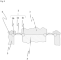
- Fig. 2 shows the basic principle of the present application.
- a first base body 2 and a first clamping device 3 are present, which are connected to one another are connected. These are arranged in a recess 5b of the second base body 5, the second base body 5 and the first base body 2 are concentric to each other.
- a second clamping device 6 is provided on the second base body 5. This also has a corresponding recess 6b.
- the first base body 2 is movable relative to the second base body 3.
- a first groove 4a and a second groove 4b are provided in the radially outer region, these together form the first receiving device 4.
- a first thickening 1b of the sealing device 1 is clamped into this receiving device 4.
- a third groove 7a and a fourth groove 7b are provided, these together form the second receiving device 7. These grooves 7a and 7b together clamp the second thickening 1c of the sealing device 1.
- a main body 1a of the sealing device is provided between the first thickening 1b and the second thickening 1c. This can be made of bellows, for example. Since the transitions between the first base body 2 and the first clamping device 3 and the second base body 5 and the second clamping device 6 are covered by the sealing device 1, there is no difference from the outside compared to Fig.1 All differences are covered by the sealing device 1.
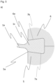
- Fig. 3 a shows a detailed view of a second thickening 1c, to which a main body 1a of a sealing device is connected.
- a third groove 7a with a semicircular profile is provided, accordingly a fourth groove 7b is provided in the second clamping device 6, this also has a semicircular profile.
- the grooves 7a and 7b are arranged radially in the outer region of the second base body 5 and the second clamping device 6.
- a third edge 5a and a fourth edge 6a are provided at the radially outer end of the second base body 5 and the second clamping device 6.
- edges 5a, 6a taper to a point and thus clamp the second thickening 1c and do not allow a gap between the second base body 5 or the second clamping device 6 and the second thickening 1c. If tension or stress occurs on the main body 1a, this third edge 5a and fourth edge 6a also ensure that the first thickening is held securely in the grooves 7a and 7b and cannot be pulled out - at the same time that no damage or cracks occur in the main body 1a or the second thickening 1c. This is particularly advantageous if the sealing device 1 is subjected to frequent movements.
- Fig. 3 b shows a detailed view of a first thickening 1b, to which a main body 1a of a sealing device is connected.
- a groove 4a with a semicircular profile is provided in the first base body 2, and a second groove 4b is provided in the first clamping device 3, which also has a semicircular profile.
- the grooves 4a and 4b are arranged radially in the outer region of the first base body 2 and the first clamping device 3.
- a first edge 2a and a second edge 3a are provided at the radially outer end of the first base body 2 and the first clamping device 3.
- edges 2a, 3a taper to a point and thus clamp the first thickening 1b and do not allow any gap between the first base body 2 or the first clamping device 3 and the first thickening 1b. If tension or stress occurs on the main body 1a, this first edge 2a and second edge 3a also ensure that the first thickening is held securely in the grooves 4a and 4b and cannot be pulled out - at the same time that no damage or cracks occur in the main body 1a or first thickening 1b. This is particularly advantageous if the sealing device 1 is subjected to frequent movements.
- a sealing device 1 consisting of main body 1a, first thickening 1b and second thickening 1c, is again provided between a first base body 2 and a second base body 5.
- the first base body 2 is in turn covered by a first clamping device 3, here a first groove 4a and a second groove 4b are provided, which together form the first receiving device 4 in which the first thickening 1b is clamped.
- the connection between the first base body 2 and the first clamping device 3 is made in this case by a first connecting device 8, which in the present embodiment is a screw.
- the second thickening 1c is provided between the second base body 5 and the second clamping device 6, here too there are corresponding grooves 7a and 7b, which form the second receiving device 7.
- the first base body 2 is arranged concentrically within this recess.
- the second base body 5 and the second clamping device 6 are connected by means of a second connecting device 9, which consists of a first thread 9a and a second thread 9b.
- a projection 6c is provided on the underside of the second clamping device, in which the second thread 9b is provided as an external thread.
- the first thread 9a is provided as an internal thread within the recess 5b of the second base body 5.
- the second clamping device 6 can thus be screwed into the second base body 5 so that the second thickening 1c of the sealing device 1 is securely clamped in the second receiving device 7, which consists of a third groove 7a and a fourth groove 7b.
- the second thickening 1c can thus be clamped first because the second clamping device 6, which can be screwed into the second base body 5, is easily accessible.
- the first thickening 1b can then be clamped accordingly between the first base body 2 and the first clamping device 3.
- the screw 8 is then easily accessible from the outside.
- the first base body 2 is in turn movable relative to the second base body 3.
- Fig. 5 a shows a similar representation as the Fig. 2 .
- the second thickening 1c is, however, trapezoidal in shape.
- the shape of the third groove 7a in the second base body 5 and the fourth groove 7b in the second clamping device 6 is adapted accordingly.
- the third edge 5a and the fourth edge 6a have an acute angle - however, this is larger (ie less acute) than in Fig.3 .
- the first thickening 1b, the first groove 4a and the second groove 4b are not shown - but they have the same shapes as the second thickening 1c, the third groove 7a and the fourth groove 7b.
- Fig. 5 b shows the use of Fig. 5 a) shown second thickening 1c. Except for the shape of the first thickening 1b, second thickening 1c, first groove 4a, second groove 4b, third groove 7a and fourth groove 7b, all components of the system are the same as in Fig.4 .
- Fig.6 shows a sealing device 1 (again with main body 1a, first thickening 1b and second thickening 1c) as a bellows for connecting radially offset interfaces; here too, good sealing and good fatigue strength can be achieved with the help of the new connection concept.
- the first base body 2 and the first clamping device 3 are arranged radially on the inside, the second base body 5 and the second clamping device 6 are arranged radially on the outside. Areas that are difficult to clean can thus be avoided.
- the sealing device connects an outer side of the first base body 2 and the first clamping device 3 with an inner side of the second base body 5 and the second clamping device 6.
- Fig.7 also shows a sealing device 1 for connecting radially offset interfaces, in contrast to Fig.6 however, with several folds in the main body 1, to minimize the force shunt or for larger relative movements.
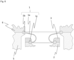
- Fig.8 also shows a sealing device 1 for connecting radially offset interfaces.
- the sealing device 1 connects an inner side of the first base body 2 and the first clamping device 3 with an inner side of the second base body 5 and the second clamping device 6.
- first thickening 1b and the second thickening 1c can have different shapes - it is only important that there is an accumulation of material compared to the main body 1a of the sealing device 1.
- connection between the first base body 2 and the first clamping element 3 or the second base body 5 and the second clamping element 6 can also be provided in a non-detachable manner, e.g. by gluing, welding, etc.
- the first base body 2, the second base body 5, the first clamping device 3 and the second clamping device 6 can be made of metal (e.g. stainless steel, aluminum) or plastic.
Landscapes
- Engineering & Computer Science (AREA)
- General Engineering & Computer Science (AREA)
- Mechanical Engineering (AREA)
- Sealing Devices (AREA)
- Clamps And Clips (AREA)
- Specific Sealing Or Ventilating Devices For Doors And Windows (AREA)
Applications Claiming Priority (1)
| Application Number | Priority Date | Filing Date | Title |
|---|---|---|---|
| DE202022105676.5U DE202022105676U1 (de) | 2022-10-07 | 2022-10-07 | Hygienegerechtes Dichtelement |
Publications (3)
| Publication Number | Publication Date |
|---|---|
| EP4350177A1 true EP4350177A1 (fr) | 2024-04-10 |
| EP4350177B1 EP4350177B1 (fr) | 2025-10-29 |
| EP4350177C0 EP4350177C0 (fr) | 2025-10-29 |
Family
ID=84388411
Family Applications (1)
| Application Number | Title | Priority Date | Filing Date |
|---|---|---|---|
| EP23195107.0A Active EP4350177B1 (fr) | 2022-10-07 | 2023-09-04 | Élément d'étanchéité hygiénique |
Country Status (3)
| Country | Link |
|---|---|
| EP (1) | EP4350177B1 (fr) |
| DE (1) | DE202022105676U1 (fr) |
| ES (1) | ES3059599T3 (fr) |
Citations (6)
| Publication number | Priority date | Publication date | Assignee | Title |
|---|---|---|---|---|
| DE1970306U (de) * | 1965-05-28 | 1967-10-12 | Gulde Regelarmaturen K G | Rollmembrane als dichtungselement zwischen kolben und zylinder. |
| JPS485052Y1 (fr) * | 1970-03-20 | 1973-02-08 | ||
| DE19509491A1 (de) * | 1994-03-30 | 1995-10-05 | Zeiss Carl Fa | Rollmembran |
| US20120248712A1 (en) * | 2011-03-28 | 2012-10-04 | Toyota Jidosha Kabushiki Kaisha | Boot seal for variable compression-rate engine |
| EP3246605A1 (fr) | 2016-05-18 | 2017-11-22 | Gemü Gebr. Müller Apparatebau Gmbh & Co. Kommanditgesellschaf | Soupape à membrane |
| KR102100807B1 (ko) | 2019-04-15 | 2020-04-14 | 주식회사 에이티에스 | 댐퍼 내장형 에어스프링 |
-
2022
- 2022-10-07 DE DE202022105676.5U patent/DE202022105676U1/de active Active
-
2023
- 2023-09-04 ES ES23195107T patent/ES3059599T3/es active Active
- 2023-09-04 EP EP23195107.0A patent/EP4350177B1/fr active Active
Patent Citations (6)
| Publication number | Priority date | Publication date | Assignee | Title |
|---|---|---|---|---|
| DE1970306U (de) * | 1965-05-28 | 1967-10-12 | Gulde Regelarmaturen K G | Rollmembrane als dichtungselement zwischen kolben und zylinder. |
| JPS485052Y1 (fr) * | 1970-03-20 | 1973-02-08 | ||
| DE19509491A1 (de) * | 1994-03-30 | 1995-10-05 | Zeiss Carl Fa | Rollmembran |
| US20120248712A1 (en) * | 2011-03-28 | 2012-10-04 | Toyota Jidosha Kabushiki Kaisha | Boot seal for variable compression-rate engine |
| EP3246605A1 (fr) | 2016-05-18 | 2017-11-22 | Gemü Gebr. Müller Apparatebau Gmbh & Co. Kommanditgesellschaf | Soupape à membrane |
| KR102100807B1 (ko) | 2019-04-15 | 2020-04-14 | 주식회사 에이티에스 | 댐퍼 내장형 에어스프링 |
Also Published As
| Publication number | Publication date |
|---|---|
| EP4350177B1 (fr) | 2025-10-29 |
| ES3059599T3 (en) | 2026-03-23 |
| EP4350177C0 (fr) | 2025-10-29 |
| DE202022105676U1 (de) | 2022-11-22 |
Similar Documents
| Publication | Publication Date | Title |
|---|---|---|
| EP1760854B1 (fr) | Traversée de câble | |
| EP0229861A1 (fr) | Raccord pour tuyaux de champs pétroliers et gaziers | |
| EP3153830B1 (fr) | Support de charge ayant un dispositif de verrouillage | |
| EP2021743B1 (fr) | Joint d'étanchéité moulé et capteur de processus comprenant un tel agencement de joint | |
| CH668629A5 (de) | Rohrverschraubung mit beruehrungsdichtung. | |
| EP3069830A2 (fr) | Organe de prehension comprenant un element courbe deformable elastiquement dans une direction preferentielle et support | |
| DE102016102206A1 (de) | Schieberventil | |
| EP4299961A1 (fr) | Dispositif de réception et/ou de conduite des matières en vrac et/ou des poudres doté d'un dispositif de liaison à bride | |
| EP4350177B1 (fr) | Élément d'étanchéité hygiénique | |
| DE102011107352A1 (de) | Ringfilter für flüssige oder gasförmige Medien | |
| CH653769A5 (de) | Innenmesstastvorrichtung. | |
| WO2011128007A1 (fr) | Fixation pour un objet cylindrique dans une plaque | |
| EP0412997B1 (fr) | Garniture d'etancheite | |
| EP2887047A1 (fr) | Cadre coulissant, dispositif de contrôle et procédé de détermination d'au moins une propriété d'un échantillon | |
| WO2021160640A1 (fr) | Ensemble palier | |
| EP2527694A1 (fr) | Joint fendu en forme de griffe ou de mâchoire | |
| WO2000068588A1 (fr) | Dispositif recepteur pour au moins un arbre monte de maniere etanche dans un carter | |
| EP2112478B1 (fr) | Capteur pour zones de production exigeantes au niveau hygiénique | |
| DE19944131B4 (de) | Klemmring | |
| EP3309412B1 (fr) | Vis de sécurité pour applications hygiéniques | |
| DE202011050291U1 (de) | Federelement | |
| DE60002940T2 (de) | Eckverbindung für Rahmenleisten | |
| CH615387A5 (en) | Offset rotary printing machine | |
| EP3172140B1 (fr) | Système de fermeture à vis | |
| EP4345423B1 (fr) | Unité de capteur |
Legal Events
| Date | Code | Title | Description |
|---|---|---|---|
| PUAI | Public reference made under article 153(3) epc to a published international application that has entered the european phase |
Free format text: ORIGINAL CODE: 0009012 |
|
| STAA | Information on the status of an ep patent application or granted ep patent |
Free format text: STATUS: THE APPLICATION HAS BEEN PUBLISHED |
|
| STAA | Information on the status of an ep patent application or granted ep patent |
Free format text: STATUS: REQUEST FOR EXAMINATION WAS MADE |
|
| AK | Designated contracting states |
Kind code of ref document: A1 Designated state(s): AL AT BE BG CH CY CZ DE DK EE ES FI FR GB GR HR HU IE IS IT LI LT LU LV MC ME MK MT NL NO PL PT RO RS SE SI SK SM TR |
|
| 17P | Request for examination filed |
Effective date: 20240322 |
|
| RBV | Designated contracting states (corrected) |
Designated state(s): AL AT BE BG CH CY CZ DE DK EE ES FI FR GB GR HR HU IE IS IT LI LT LU LV MC ME MK MT NL NO PL PT RO RS SE SI SK SM TR |
|
| P01 | Opt-out of the competence of the unified patent court (upc) registered |
Effective date: 20240429 |
|
| STAA | Information on the status of an ep patent application or granted ep patent |
Free format text: STATUS: EXAMINATION IS IN PROGRESS |
|
| 17Q | First examination report despatched |
Effective date: 20241210 |
|
| GRAP | Despatch of communication of intention to grant a patent |
Free format text: ORIGINAL CODE: EPIDOSNIGR1 |
|
| STAA | Information on the status of an ep patent application or granted ep patent |
Free format text: STATUS: GRANT OF PATENT IS INTENDED |
|
| INTG | Intention to grant announced |
Effective date: 20250701 |
|
| GRAS | Grant fee paid |
Free format text: ORIGINAL CODE: EPIDOSNIGR3 |
|
| GRAA | (expected) grant |
Free format text: ORIGINAL CODE: 0009210 |
|
| STAA | Information on the status of an ep patent application or granted ep patent |
Free format text: STATUS: THE PATENT HAS BEEN GRANTED |
|
| P04 | Withdrawal of opt-out of the competence of the unified patent court (upc) registered |
Free format text: CASE NUMBER: UPC_APP_4200_4350177/2025 Effective date: 20250825 |
|
| AK | Designated contracting states |
Kind code of ref document: B1 Designated state(s): AL AT BE BG CH CY CZ DE DK EE ES FI FR GB GR HR HU IE IS IT LI LT LU LV MC ME MK MT NL NO PL PT RO RS SE SI SK SM TR |
|
| REG | Reference to a national code |
Ref country code: CH Ref legal event code: F10 Free format text: ST27 STATUS EVENT CODE: U-0-0-F10-F00 (AS PROVIDED BY THE NATIONAL OFFICE) Effective date: 20251029 Ref country code: GB Ref legal event code: FG4D Free format text: NOT ENGLISH |
|
| REG | Reference to a national code |
Ref country code: IE Ref legal event code: FG4D Free format text: LANGUAGE OF EP DOCUMENT: GERMAN |
|
| U01 | Request for unitary effect filed |
Effective date: 20251029 |
|
| U07 | Unitary effect registered |
Designated state(s): AT BE BG DE DK EE FI FR IT LT LU LV MT NL PT RO SE SI Effective date: 20251104 |
|
| REG | Reference to a national code |
Ref country code: ES Ref legal event code: FG2A Ref document number: 3059599 Country of ref document: ES Kind code of ref document: T3 Effective date: 20260323 |
|
| PG25 | Lapsed in a contracting state [announced via postgrant information from national office to epo] |
Ref country code: NO Free format text: LAPSE BECAUSE OF FAILURE TO SUBMIT A TRANSLATION OF THE DESCRIPTION OR TO PAY THE FEE WITHIN THE PRESCRIBED TIME-LIMIT Effective date: 20260129 |
|
| PG25 | Lapsed in a contracting state [announced via postgrant information from national office to epo] |
Ref country code: HR Free format text: LAPSE BECAUSE OF FAILURE TO SUBMIT A TRANSLATION OF THE DESCRIPTION OR TO PAY THE FEE WITHIN THE PRESCRIBED TIME-LIMIT Effective date: 20251029 |
|
| PG25 | Lapsed in a contracting state [announced via postgrant information from national office to epo] |
Ref country code: RS Free format text: LAPSE BECAUSE OF FAILURE TO SUBMIT A TRANSLATION OF THE DESCRIPTION OR TO PAY THE FEE WITHIN THE PRESCRIBED TIME-LIMIT Effective date: 20260129 |
|
| PG25 | Lapsed in a contracting state [announced via postgrant information from national office to epo] |
Ref country code: IS Free format text: LAPSE BECAUSE OF FAILURE TO SUBMIT A TRANSLATION OF THE DESCRIPTION OR TO PAY THE FEE WITHIN THE PRESCRIBED TIME-LIMIT Effective date: 20260228 |
|
| PG25 | Lapsed in a contracting state [announced via postgrant information from national office to epo] |
Ref country code: PL Free format text: LAPSE BECAUSE OF FAILURE TO SUBMIT A TRANSLATION OF THE DESCRIPTION OR TO PAY THE FEE WITHIN THE PRESCRIBED TIME-LIMIT Effective date: 20251029 |