EP4350192A1 - Appareil et procédé de détection, dispositif informatique, support de stockage et produit programme - Google Patents
Appareil et procédé de détection, dispositif informatique, support de stockage et produit programme Download PDFInfo
- Publication number
- EP4350192A1 EP4350192A1 EP23800305.7A EP23800305A EP4350192A1 EP 4350192 A1 EP4350192 A1 EP 4350192A1 EP 23800305 A EP23800305 A EP 23800305A EP 4350192 A1 EP4350192 A1 EP 4350192A1
- Authority
- EP
- European Patent Office
- Prior art keywords
- camera
- move
- sliding assembly
- driving apparatus
- control instruction
- Prior art date
- Legal status (The legal status is an assumption and is not a legal conclusion. Google has not performed a legal analysis and makes no representation as to the accuracy of the status listed.)
- Pending
Links
Images


Classifications
-
- H—ELECTRICITY
- H04—ELECTRIC COMMUNICATION TECHNIQUE
- H04N—PICTORIAL COMMUNICATION, e.g. TELEVISION
- H04N23/00—Cameras or camera modules comprising electronic image sensors; Control thereof
- H04N23/60—Control of cameras or camera modules
- H04N23/695—Control of camera direction for changing a field of view, e.g. pan, tilt or based on tracking of objects
-
- H—ELECTRICITY
- H04—ELECTRIC COMMUNICATION TECHNIQUE
- H04N—PICTORIAL COMMUNICATION, e.g. TELEVISION
- H04N23/00—Cameras or camera modules comprising electronic image sensors; Control thereof
- H04N23/90—Arrangement of cameras or camera modules, e.g. multiple cameras in TV studios or sports stadiums
-
- H—ELECTRICITY
- H04—ELECTRIC COMMUNICATION TECHNIQUE
- H04N—PICTORIAL COMMUNICATION, e.g. TELEVISION
- H04N23/00—Cameras or camera modules comprising electronic image sensors; Control thereof
- H04N23/56—Cameras or camera modules comprising electronic image sensors; Control thereof provided with illuminating means
-
- H—ELECTRICITY
- H04—ELECTRIC COMMUNICATION TECHNIQUE
- H04N—PICTORIAL COMMUNICATION, e.g. TELEVISION
- H04N23/00—Cameras or camera modules comprising electronic image sensors; Control thereof
- H04N23/70—Circuitry for compensating brightness variation in the scene
- H04N23/74—Circuitry for compensating brightness variation in the scene by influencing the scene brightness using illuminating means
-
- Y—GENERAL TAGGING OF NEW TECHNOLOGICAL DEVELOPMENTS; GENERAL TAGGING OF CROSS-SECTIONAL TECHNOLOGIES SPANNING OVER SEVERAL SECTIONS OF THE IPC; TECHNICAL SUBJECTS COVERED BY FORMER USPC CROSS-REFERENCE ART COLLECTIONS [XRACs] AND DIGESTS
- Y02—TECHNOLOGIES OR APPLICATIONS FOR MITIGATION OR ADAPTATION AGAINST CLIMATE CHANGE
- Y02E—REDUCTION OF GREENHOUSE GAS [GHG] EMISSIONS, RELATED TO ENERGY GENERATION, TRANSMISSION OR DISTRIBUTION
- Y02E60/00—Enabling technologies; Technologies with a potential or indirect contribution to GHG emissions mitigation
- Y02E60/10—Energy storage using batteries
Definitions
- the present application relates to the technical field of communications, and in particular, to a detection apparatus and method, a computer device, a storage medium, and a program product.
- a filling port of the cell needs to be sealed by means of sealing pin welding, to prevent liquid leakage, so as to ensure the sealing performance of the cell with liquid filled.
- a 3D camera and a 2D camera are secured onto the same movable module.
- the 2D camera captures a 2D image of the cell under the drive of the movable module.
- the movable module drives the 3D camera to return along an original path to capture a 3D image of the cell.
- the effectiveness of sealing pin welding is detected based on the 2D image and the 3D image.
- the current detection method has the problem of poor image quality obtained, resulting in erroneous detection.
- the present application provides a detection apparatus, the detection apparatus including a support, a driving apparatus provided on the support, and a first movable module, where the driving apparatus includes a first driving apparatus, and the first driving apparatus is connected to the first movable module; the first movable module is provided with a first sliding assembly, and a first camera connected to the first sliding assembly; and the first driving apparatus is configured to control the first sliding assembly to move in a first direction to drive the first camera to move close to or away from a material to be photographed, where an included angle between the first direction and a vertical direction is less than or equal to a preset angle threshold.
- the first sliding assembly can be controlled, based on the compensation information in the first control instruction, to move in the first direction to drive the first camera to move close to or away from the material to be photographed, such that the distance between the first camera and the material to be photographed is within a depth of field range of the first camera. Therefore, the problem of losing pixels from the first camera can be avoided, thereby improving the quality of a 3D image, and thus improving the accuracy of detecting the effectiveness of sealing pin welding.
- the driving apparatus further includes a second driving apparatus provided on the first movable module, and the first movable module is further provided with a rotating assembly connected to the first camera; and the second driving apparatus is configured to control the rotating assembly to rotate in a preset rotation direction to drive the first camera to rotate.
- the second driving apparatus can control the rotating assembly 18 to rotate in the preset rotation direction, to drive the first camera to rotate, and the first camera performs image capture in an rotating manner, where a light source used during 3D image capture is a laser light source, laser light emitted by the laser light source forms a "cross" shape with a weld bead of a sealing pin, the vertical line representing the weld bead, and the horizontal line representing the laser light, and the laser light can move on this vertical line, to ensure that the laser light cannot be affected by the height of the weld bead when being reflected to a lens of the first camera. Therefore, the problem of losing pixels from the first camera is avoided, further improving the quality of a 3D image, and thus improving the accuracy of detecting the effectiveness of sealing pin welding.
- a light source used during 3D image capture is a laser light source
- laser light emitted by the laser light source forms a "cross" shape with a weld bead of a sealing pin, the vertical line representing the wel
- the driving apparatus further includes a third driving apparatus, where the third driving apparatus is connected to a second movable module, and the second movable module is connected to the first movable module; the second movable module is provided with a second sliding assembly connected to the first camera; and the third driving apparatus is configured to control the second sliding assembly to move in a second direction to drive the first camera to move in the second direction.
- a PLC can send a material reaching signal to a computer device and control a 2D light source to be turned on; the computer device sends a picture photographing instruction to a second camera after receiving the material reaching signal; the second camera starts to photograph the material to be photographed after receiving the picture photographing instruction, to obtain a 2D image; the computer device obtains the 2D image, determines a center position of a sealing pin on the material to be photographed based on the 2D image, and sends the center position to the PLC; the PLC sends a third control instruction including the center position to the third driving apparatus; and the third driving apparatus controls, based on the center position in the third control instruction, the second sliding assembly to move in the second direction to drive the first camera to move in the second direction.
- a center of rotation of the first camera during rotation can be adjusted based on the center position before controlling the first camera to rotate, thereby ensuring that the center of rotation overlaps with or nearly overlaps with the center position of the sealing pin on the material to be photographed, and further improving the quality of an obtained 3D image.
- the detection apparatus further includes a second camera connected to the second sliding assembly; the second camera is provided with a coaxial light source and a ring light source;
- the center position is a position determined based on a material picture photographed by the second camera; and the third driving apparatus is configured to determine position adjustment information of the first camera based on the center position in the third control instruction, and control, based on the position adjustment information, the second sliding assembly to move in a second direction to drive the first camera to move in the second direction.
- the second movable module includes a first horizontal module and a second horizontal module connected to each other; the first horizontal module and the second horizontal module are both connected to the first movable module; the second sliding assembly includes a first horizontal sliding assembly provided on the first horizontal module and a second horizontal sliding assembly provided on the second horizontal module; and the third driving apparatus is configured to control the first horizontal sliding assembly to move in a first horizontal direction, and/or control the second horizontal sliding assembly to move in a second horizontal direction.
- the present application further provides a detection method, which is applied to a detection apparatus according to any one of claims 1 to 6.
- the method includes:
- the detection method further includes: controlling, based on a second control instruction, a rotating assembly to rotate in a preset rotation direction to drive the first camera to rotate.
- the detection method further includes:
- the detection method further includes: controlling, based on a fourth control instruction, the second sliding assembly to move in a third direction to drive a second camera to move in the third direction.
- the controlling, based on the center position in the third control instruction, a second sliding assembly to move in a second direction includes:
- the method further includes: controlling, based on a fifth control instruction, a first horizontal sliding assembly to move in a first horizontal direction, and/or controlling a second horizontal sliding assembly to move in a second horizontal direction.
- the present application further provides a detection apparatus, the detection apparatus including:
- the present application further provides a computer device.
- the computer device includes a memory and a processor, where the memory stores a computer program, and the processor implements the steps of any one of the methods as described above.
- the present application further provides a computer-readable storage medium.
- the computer-readable storage medium has stored thereon a computer program that, when executed by a processor, implements the steps of any one of the methods as described above.
- the present application further provides a computer program product.
- the computer program product includes a computer program that, when executed by a processor, implements the steps of any one of the methods as described above.
- the detection apparatus includes a support, a driving apparatus provided on the support, and a first movable module, where the driving apparatus includes a first driving apparatus, and the first driving apparatus is connected to the first movable module; the first movable module is provided with a first sliding assembly, and a first camera connected to the first sliding assembly; and the first driving apparatus is configured to control the first sliding assembly to move in a first direction to drive the first camera to move close to or away from a material to be photographed, where an included angle between the first direction and a vertical direction is less than or equal to a preset angle threshold.
- the first sliding assembly can be controlled to move in the first direction to drive the first camera to move close to or away from the material to be photographed, such that the distance between the first camera and the material to be photographed is within a depth of field range of the first camera. Therefore, the problem of losing pixels from the first camera can be avoided, thereby improving the quality of a 3D image, and thus improving the accuracy of detecting the effectiveness of sealing pin welding.
- a plurality of means two or more (including two), similarly the term “a plurality of groups” means two or more groups (including two groups), and the term “a plurality of pieces” means two or more pieces (including two pieces).
- the technical terms such as “install”, “couple”, “connect”, and “fix” should be understood in a broad sense, for example, they may be a fixed connection, a detachable connection, or an integrated connection; may be a mechanical connection or an electric connection; and may be a direct connection or an indirect connection by means of an intermediate medium, or may be communication between interiors of two elements or interaction between the two elements.
- install may be a fixed connection, a detachable connection, or an integrated connection
- the process of detecting the effectiveness of sealing pin welding is as follows.
- a 3D camera and a 2D camera are secured onto the same movable module.
- the 2D camera captures a 2D image of the cell under the drive of the movable module.
- the movable module drives the 3D camera to return along an original path to capture a 3D image of the cell.
- the effectiveness of sealing pin welding is detected based on the 2D image and the 3D image.
- the depth of field range of the 3D camera is a range in which a camera can perform clear imaging.
- the depth of field range of the 3D camera is 30 mm to 35 mm, and if the actual distance is not within this depth of field range of 30 mm to 35 mm, erroneous detection of the effectiveness of sealing pin welding may be caused.
- FIG. 1 is a schematic structural diagram of a detection apparatus according to an embodiment of the present application
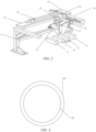
- FIG. 2 is a schematic structural diagram of another detection apparatus according to an embodiment of the present application
- FIG. 1 is a top view of the detection apparatus.
- the detection apparatus includes a support 11, a driving apparatus provided on the support 11, and a first movable module 12, where the driving apparatus includes a first driving apparatus, and the first driving apparatus is connected to the first movable module 12; the first movable module 12 is provided with a first sliding assembly, and a first camera 13 connected to the first sliding assembly; and the first driving apparatus is configured to control the first sliding assembly to move in a first direction to drive the first camera 13 to move close to or away from a material to be photographed, where an included angle between the first direction and a vertical direction is less than or equal to a preset angle threshold.
- the preset angle threshold may be a value equal to 0 or close to 0. For example, if the preset angle threshold is equal to 1°, the first direction may be the same direction as the vertical direction, or the included angle between the first direction and the vertical direction may be less than 1°.
- the first camera may be a 3D camera.
- the material to be photographed includes, for example, cells 14, 15, 16, and 17 shown in FIG. 2 .
- the material to be photographed may include one or more cells.
- a distance measurement device can be used to measure an actual distance between each material to be photographed and the first camera 13, and send the actual distance to a computer device.
- the computer device determines compensation information based on the actual distance and a preset depth of field range of the first camera 13, and sends the compensation information to a programmable logic controller (PLC).
- PLC programmable logic controller
- the PLC sends a first control instruction including the compensation information to the first driving apparatus, such that the first driving apparatus moves close to or away from the material to be photographed based on the compensation information in the first control instruction, thereby ensuring that the distance between the material to be photographed and the first camera 13 is within the depth of field range of the first camera 13.
- the computer device may determine that the compensation information is equal to a difference between 37 and 35, that is, the compensation information may be 2 mm.
- the first sliding assembly needs to be controlled to move in the first direction to drive the first camera 13 to move close to the material to be photographed, such that the distance between the first camera 13 and the material to be photographed is within the depth of field range after the first sliding assembly is controlled to move in the first direction.
- the computer device may determine that the compensation information is equal to a difference between 30 and 28, that is, the compensation information is 2 mm.
- the first sliding assembly needs to be controlled to move in the first direction to drive the first camera 13 to move away from the material to be photographed, such that the distance between the first camera 13 and the material to be photographed is within the depth of field range after the first sliding assembly is controlled to move in the first direction.
- the first sliding assembly can be controlled to move in the first direction to drive the first camera 13 to move close to or away from the material to be photographed, such that the distance between the first camera 13 and the material to be photographed is within a depth of field range of the first camera 13. Therefore, the problem of losing pixels from the first camera 13 can be avoided, thereby improving the quality of a 3D image, and thus improving the accuracy of detecting the effectiveness of sealing pin welding.
- the driving apparatus further includes a second driving apparatus provided on the first movable module 12, and the first movable module 12 is further provided with a rotating assembly 18 connected to the first camera 13; and the second driving apparatus is configured to control the rotating assembly 18 to rotate in a preset rotation direction to drive the first camera 13 to rotate.
- controlling the first camera 13 to rotate can enable the first camera 1 to rotate during photographing, such that the problem of a relatively low quality of a 3D image can be further solved.
- Controlling the first camera 13 to rotate during photographing is enabled in the following way: after the material to be photographed reaches a detection station, a PLC sends a second control instruction to the second driving apparatus; based on the second control instruction, the second driving apparatus can drive an encoder connected to the second driving apparatus to rotate; the encoder may generate a trigger signal during rotation, and then send the trigger signal to the first camera 13; and the first camera 13 rotates in the preset rotation direction after receiving the trigger signal, to drive the first camera 13 to rotate during photographing.
- the preset rotation direction may be a clockwise direction or a counterclockwise direction.
- the second driving apparatus can control, based on the second control instruction, the rotating assembly 18 to rotate in the preset rotation direction, to drive the first camera 13 to rotate during photographing, and the first camera 13 captures an image in an rotating manner, where a light source used during 3D image capture is a laser light source, laser light emitted by the laser light source forms a "cross" shape with a weld bead of a sealing pin, the vertical line in the shape representing the weld bead, and the horizontal line in the shape representing the laser light, and the laser light can move on this vertical line, to ensure that the laser light cannot be affected by the height of the weld bead when being reflected to a lens of the first camera 13. Therefore, the problem of losing pixels from the first camera 13 is avoided, further improving the quality of a 3D image, and thus improving the accuracy of detecting the effectiveness of sealing pin welding.
- a light source used during 3D image capture is a laser light source
- laser light emitted by the laser light source forms a "cross" shape with
- the driving apparatus further includes a third driving apparatus, where the third driving apparatus is connected to a second movable module, and the second movable module is connected to the first movable module 12; the second movable module is provided with a second sliding assembly connected to the first camera 13; and the third driving apparatus is configured to control the second sliding assembly to move in a second direction to drive the first camera 13 to move in the second direction.
- the second direction may include a horizontal direction of the X axis 24 and/or a horizontal direction of the Y axis 25.
- a PLC can send a material reaching signal to a computer device and control a 2D light source to be turned on; the computer device sends a picture photographing instruction to a second camera 19 after receiving the material reaching signal; the second camera 19 starts to photograph the material to be photographed after receiving the picture photographing instruction, to obtain a 2D image; the computer device obtains the 2D image, determines a center position of a sealing pin on the material to be photographed based on the 2D image, and sends the center position to the PLC; the PLC sends a third control instruction including the center position to the third driving apparatus; and the third driving apparatus controls, based on the center position in the third control instruction, the second sliding assembly to move in the second direction to drive the first camera 13 to move in the second direction.
- a center of rotation of the first camera 13 during rotation can be adjusted based on the center position before controlling the first camera 13 to rotate, thereby ensuring that the center of rotation overlaps with or nearly overlaps with the center position of the sealing pin on the material to be photographed, and further improving the quality of an obtained 3D image.
- the detection apparatus further includes a second camera 19 connected to the second sliding assembly; the second camera 19 is provided with a coaxial light source 20 and a ring light source 21;
- the third direction may include a horizontal direction of the X axis 24 and/or a horizontal direction of the Y axis 25.
- the third direction in which the second camera 19 is driven to move during photographing of the 2D image of the material to be photographed is opposite to the direction in which the first camera 13 is driven to move during photographing of the 3D image of the material to be photographed.
- the material to be photographed includes four cells. After the four cells are welded side by side, a wheel is rotated to enable the four cells to flow to detection stations. After the cells flow to the detection stations, a PLC sends a material reaching signal to a computer device, the PLC controls a 2D light source to be turned on, and the second camera 19 captures a 2D image of the cell 14 at the first detection station.
- the third driving apparatus drives the second camera 19 and the first camera 13 to move to the second detection station, the PLC controls the 2D light source to be turned on, and the second camera 19 captures a 2D image of the cell 15 at the second detection station.
- the third driving apparatus drives the second camera 19 and the first camera 13 to move to the third detection station, the PLC controls the 2D light source to be turned on, and the second camera 19 captures a 2D image of the cell 16 at the third detection station.
- the third driving apparatus drives the second camera 19 and the first camera 13 to move to the fourth detection station, the PLC controls the 2D light source to be turned on, and the second camera 19 captures a 2D image of the cell 17 at the fourth detection station.
- the second camera 19 and the first camera 13 can be controlled to return to the first detection station from the fourth detection station along the original path.
- 3D images are captured for the cells at the detection stations in sequence.
- a bowl-shaped light source is used to light a weld bead on a material to be photographed during 2D image capture, and since a stepped sealing pin has a weld bead that is too high, the bowl-shaped light source emits light that cannot be reflected to a lens of the second camera 19 when being irradiated to an outer region of the weld bead, resulting in a dark outer region of the weld bead in an obtained 2D image.
- a 2D light source including a combined coaxial light source 20 and ring light source 21 is used, where the coaxial light source 20 lights the inner region of the weld bead on the material to be photographed, and the ring light source 21 lights the outer region of the weld bead, such that lighting of the inner region and the outer region of the weld bead is implemented, reducing the phenomenon of a dark outer region of the weld bead.
- FIG. 3 is a schematic diagram of a weld bead before welding according to an embodiment of the present application
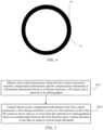
- FIG. 4 is a schematic diagram of a weld bead after welding according to an embodiment of the present application.
- FIG. 3 shows an inner region 301 and an outer region 302 of the weld bead before welding
- FIG. 4 shows an inner region 401 of the weld bead after welding and an outer region 402 thereof after welding
- the weld bead after welding is a black ring as shown in FIG. 4 .
- the center position is a position determined based on a material picture photographed by the second camera 19; and the third driving apparatus is configured to determine position adjustment information of the first camera 13 based on the center position in the third control instruction, and control, based on the position adjustment information, the second sliding assembly to move in a second direction to drive the first camera 13 to move in the second direction.
- a computer device can determine a center position of a sealing pin from a material picture photographed by the second camera 19, and send the center position to a PLC.
- the PLC sends the center position to the third driving apparatus, and the third driving apparatus can thus determine position adjustment information of the first camera 13 based on the center position, and control, based on the position adjustment information, the second sliding assembly to move in the second direction such that the first camera 13 can rotate about the center position. Therefore, the quality of an obtained 3D image is further improved.
- the second movable module includes a first horizontal module and a second horizontal module connected to each other; the first horizontal module and the second horizontal module are both connected to the first movable module 12; the second sliding assembly includes a first horizontal sliding assembly 22 provided on the first horizontal module and a second horizontal sliding assembly 23 provided on the second horizontal module; and the third driving apparatus is configured to control the first horizontal sliding assembly 22 to move in a first horizontal direction, and/or control the second horizontal sliding assembly 23 to move in a second horizontal direction, where the first horizontal direction may be perpendicular to the second horizontal direction, or a difference between an angle formed by the first horizontal direction and the second horizontal direction and 90° may be a value close to 0.
- the third driving apparatus can control the first horizontal sliding assembly 22 to move in the direction of the X axis 24; and/or the third driving apparatus can control the second horizontal sliding assembly 23 to move in the direction of the Y axis 25.
- the first horizontal direction is, for example, the direction of the X axis 24 in FIG. 2
- the second horizontal direction is, for example, the direction of the Y axis 25 in FIG. 2 .
- the second camera 19 and the first camera 13 can move left and right, and in the direction of the Y axis 25, the second camera 19 and the first camera 13 can move forward and backward.
- the second camera 19 and the first camera 18 photograph the four cells sequentially when moving in the direction of the X axis 24, and the second camera 19 and the first camera 13 adjust positions of the second camera 19 and the first camera 13 in the direction of the Y axis 25 when moving in the direction of the Y axis 25.
- the first movable module 12 may further include a fixing member 26, the fixing member 26 being connected to the second camera 19.
- the rotating assembly 18 included in the first movable module 12 is connected to the first camera
- the fixing member 26 included in the first movable module is connected to the second camera 19
- the fixing member 26 is connected to the first horizontal sliding assembly 22
- the first horizontal sliding assembly 22 can move along the X axis 24
- the X axis 24 is connected to the second horizontal sliding assembly 23
- the second horizontal sliding assembly 23 can move along the Y axis 25. Therefore, the first horizontal sliding assembly 22 and the second horizontal sliding assembly 23 can enable the second camera and the first camera to move in the directions of the X axis and the Y axis.
- the cameras in the embodiments of the present application have a detection accuracy as follows.
- the second camera has a detection accuracy of 0.0062 mm
- the first camera has an accuracy of 0.016 mm in the X direction, 0.02 mm in the Y direction, and 0.002 mm in the Z direction.
- the second camera should meet a 2D object distance of 65 ⁇ 20 mm
- the first camera should meet an object distance of 47.5 ⁇ 20 mm and an inclination angle of 20° ⁇ 15°.
- the camera is adjustable by a lifting module.
- a computer device can implement one-click adjustment of a working distance of a camera through a trigger control provided by software, such that the camera performs clear imaging.
- FIG. 5 is a schematic flowchart of a detection method according to an embodiment of the present application, and the detection method is applied to a detection apparatus according to any one of the embodiments described above.
- the method includes:
- the detection method further includes: controlling, based on a second control instruction, a rotating assembly to rotate in a preset rotation direction to drive the first camera to rotate.
- FIG. 6 is a schematic flowchart of another detection method according to an embodiment of the present application.
- the detection method includes the following steps:
- the detection method further includes: controlling, based on a fourth control instruction, the second sliding assembly to move in a third direction to drive a second camera to move in the third direction.
- FIG. 7 is a schematic flowchart of a control method for a second sliding assembly according to an embodiment of the present application, and S602 includes:
- the method further includes: controlling, based on a fifth control instruction, a first horizontal sliding assembly to move in a first horizontal direction, and/or controlling a second horizontal sliding assembly to move in a second horizontal direction.
- FIG. 8 is a schematic flowchart of yet another detection method according to an embodiment of the present application.
- the computer device obtains the detection results for the cells based on the 2D images and the 3D images of the cells by using an AI detection algorithm.
- steps in the flowchart that are involved in the embodiments described above are displayed in sequence as indicated by arrows, these steps are not necessarily sequentially executed in the order indicated by the arrows. Unless explicitly described herein, the execution of these steps is not limited to a strict order, instead, the steps may be executed in another order. In addition, at least some of the steps in the flowchart that are involved in the embodiments described above may include multiple steps or multiple stages. These steps or stages are not necessarily executed or completed at the same moment, but can be executed at different moments. These steps or stages are also not necessarily executed in sequence, but can be executed in turn or alternately with at least some of other steps or steps or stages of other steps.
- an embodiment of the present application further provides a detection apparatus for implementing the detection method involved above.
- the apparatus provides an implementation solution for solving the problems that is similar to the implementation solution described in the above method. Therefore, for specific limitations in one or more embodiments of the detection apparatus provided below, reference may be made to the above limitations on the detection method, which will not be repeated herein.
- FIG. 9 is a schematic structural diagram of a detection apparatus according to an embodiment of the present application.
- the detection apparatus 900 includes:
- the detection apparatus 900 further includes: a second control module configured to control, based on a second control instruction, a rotating assembly to rotate in a preset rotation direction to drive the first camera to rotate during photographing.
- the detection apparatus 900 includes:
- the detection apparatus further includes: a fourth control module configured to control, based on a fourth control instruction, the second sliding assembly to move in a third direction to drive a second camera to move in the third direction.
- a fourth control module configured to control, based on a fourth control instruction, the second sliding assembly to move in a third direction to drive a second camera to move in the third direction.
- the third control module is further configured to: determine position adjustment information based on the center position, where the center position is a position determined based on a material picture photographed by the second camera; and control, based on the position adjustment information, the second sliding assembly to move in the second direction, such that the first camera rotates about the center position.
- All or some of the modules in the above detection apparatus may be implemented by software, hardware, and a combination thereof.
- the modules above may be embedded, in the form of hardware, in or independent of a processor in a computer device, or may be stored, in the form of software, in a memory of the computer device, so as to be invoked by the processor to perform the operations corresponding to the modules above.
- a computer device is provided.
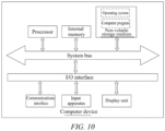
- the computer device may be a terminal, and a diagram of an internal structural thereof may be as shown in FIG. 10 .
- the computer device includes a processor, a memory, a communications interface, a display screen, and an input apparatus that are connected via a system bus.
- the processor of the computer device is used for providing computing and control capabilities.
- the memory of the computer device includes a non-volatile storage medium and an internal memory.
- the non-volatile storage medium stores an operating system and a computer program.
- the internal memory provides an environment for operation of the operating system and the computer program in the non-volatile storage medium.
- the communications interface of the computer device is used for wired or wireless communication with an external terminal, and the wireless method can be implemented by WIFI, a mobile cellular network, NFC (near-field communication), or other technologies.
- the computer program when executed by the processor, implements a detection method.
- the display screen of the computer device may be a liquid crystal display or an electronic ink display.
- the input apparatus of the computer device may be a touch layer covering the display screen, or a key, trackball or trackpad set on a casing of the computer device, or an external keyboard, trackpad or mouse, etc.
- FIG. 10 is merely a block diagram of part of the structure related to the solutions of the present application, and that does not constitute a limitation on the computer device to which the solutions of the present application are applied.
- the computer device may include more or fewer components than those shown in the drawings, or combine some components, or have different component arrangements.
- a computer device which includes a memory and a processor, where the memory stores a computer program that, when executed by the processor, implements the following steps:
- the computer program when executed by the processor, further implements the following step: controlling, based on a second control instruction, a rotating assembly to rotate in a preset rotation direction to drive the first camera to rotate.
- the computer program when executed by the processor, further implements the following steps:
- the computer program when executed by the processor, further implements the following step: controlling, based on a fourth control instruction, the second sliding assembly to move in a third direction to drive a second camera to move in the third direction.
- the computer program when executed by the processor, further implements the following steps:
- the computer program when executed by the processor, further implements the following steps: controlling, based on a fifth control instruction, a first horizontal sliding assembly to move in a first horizontal direction, and/or controlling a second horizontal sliding assembly to move in a second horizontal direction.
- a computer-readable storage medium which has stored thereon a computer program that, when executed by a processor, implements the following steps:
- the computer program when executed by the processor, further implements the following step: controlling, based on a second control instruction, a rotating assembly to rotate in a preset rotation direction to drive the first camera to rotate.
- the computer program when executed by the processor, further implements the following steps:
- the computer program when executed by the processor, further implements the following step: controlling, based on a fourth control instruction, the second sliding assembly to move in a third direction to drive a second camera to move in the third direction.
- the computer program when executed by the processor, further implements the following steps:
- the computer program when executed by the processor, further implements the following steps: controlling, based on a fifth control instruction, a first horizontal sliding assembly to move in a first horizontal direction, and/or controlling a second horizontal sliding assembly to move in a second horizontal direction.
- a computer program product which includes a computer program that, when executed by a processor, implements the following steps:
- the computer program when executed by the processor, further implements the following step: controlling, based on a second control instruction, a rotating assembly to rotate in a preset rotation direction to drive the first camera to rotate.
- the computer program when executed by the processor, further implements the following steps:
- the computer program when executed by the processor, further implements the following step: controlling, based on a fourth control instruction, the second sliding assembly to move in a third direction to drive a second camera to move in the third direction.
- the computer program when executed by the processor, further implements the following steps:
- the computer program when executed by the processor, further implements the following steps: controlling, based on a fifth control instruction, a first horizontal sliding assembly to move in a first horizontal direction, and/or controlling a second horizontal sliding assembly to move in a second horizontal direction.
- user information including, but not limited to, user device information, user personal information, etc.
- data including, but not limited to, data for analysis, data for storage, data for display, etc.
- the computer program may be stored in a non-volatile computer-readable storage medium.
- the computer program when executed, may include the procedures of the foregoing method embodiments.
- Any reference to a memory, a database, or other media used in the embodiments provided in the present application may include at least one of a non-volatile memory and/or a volatile memory.
- the non-volatile memory may include a read-only memory (ROM), a magnetic tape, a floppy disk, a flash memory, an optical memory, a high-density embedded non-volatile memory, a resistive random access memory (ReRAM), a magnetoresistive random access memory (MRAM), a ferroelectric random access memory (FRAM), a phase change memory (PCM), a graphene memory, etc.
- the volatile memory may include a random access memory (RAM), an external cache memory, etc.
- the RAM may be in various forms, such as a static random access memory (SRAM) or a dynamic random access memory (DRAM).
- the database involved in the embodiments provided in the present application may include at least one of a relational database and a non-relational database.
- the non-relational database may include a blockchain-based distributed database, etc., and is not limited thereto.
- the processor involved in the embodiments provided in the present application may be a general-purpose processor, a central processor, a graphics processor, a digital signal processor, a programmable logic device, a quantum computing-based data processing logic device, etc., and is not limited thereto.
Landscapes
- Engineering & Computer Science (AREA)
- Multimedia (AREA)
- Signal Processing (AREA)
- Length Measuring Devices By Optical Means (AREA)
Applications Claiming Priority (2)
| Application Number | Priority Date | Filing Date | Title |
|---|---|---|---|
| CN202211034358.7A CN115823412B (zh) | 2022-08-26 | 2022-08-26 | 检测装置、方法、计算机设备、存储介质以及程序产品 |
| PCT/CN2023/084763 WO2024040968A1 (fr) | 2022-08-26 | 2023-03-29 | Appareil et procédé de détection, dispositif informatique, support de stockage et produit programme |
Publications (2)
| Publication Number | Publication Date |
|---|---|
| EP4350192A1 true EP4350192A1 (fr) | 2024-04-10 |
| EP4350192A4 EP4350192A4 (fr) | 2024-10-09 |
Family
ID=89995412
Family Applications (1)
| Application Number | Title | Priority Date | Filing Date |
|---|---|---|---|
| EP23800305.7A Pending EP4350192A4 (fr) | 2022-08-26 | 2023-03-29 | Appareil et procédé de détection, dispositif informatique, support de stockage et produit programme |
Country Status (2)
| Country | Link |
|---|---|
| US (1) | US12574646B2 (fr) |
| EP (1) | EP4350192A4 (fr) |
Families Citing this family (1)
| Publication number | Priority date | Publication date | Assignee | Title |
|---|---|---|---|---|
| CN119534333A (zh) * | 2025-01-22 | 2025-02-28 | 合肥东昇智能装备股份有限公司 | 一种基于相机的全幅薄膜检测装置 |
Family Cites Families (18)
| Publication number | Priority date | Publication date | Assignee | Title |
|---|---|---|---|---|
| DE3043849A1 (de) | 1980-11-21 | 1982-07-08 | Koninklijke Textielfabrieken Nijverdal-Ten Gate N.V., Almelo | Verfahren zum beschauen einer reflektierenden und/oder transparenten, sich bewegenden bahn und beschaumaschine zur durchfuehrung des verfahrens |
| JP2000266691A (ja) * | 1999-03-16 | 2000-09-29 | Olympus Optical Co Ltd | 外観検査装置 |
| SG138491A1 (en) * | 2006-06-21 | 2008-01-28 | Generic Power Pte Ltd | Method and apparatus for 3-dimensional vision and inspection of ball and like protrusions of electronic components |
| KR20110061001A (ko) * | 2009-12-01 | 2011-06-09 | 주식회사 고영테크놀러지 | 기판 검사방법 및 이를 이용한 기판 검사장치 |
| DE102010050445B4 (de) | 2010-11-04 | 2014-02-20 | Göpel electronic GmbH | Anordnung und Verfahren zur Korrektur von Messpositionen von zur Inspektion elektronischer Flachbaugruppen aufgenommener Messbilder |
| US9952162B2 (en) * | 2013-12-13 | 2018-04-24 | Robert Scott Simmons | Optical inspection system for printed circuit board or the like |
| US20160193680A1 (en) * | 2015-01-07 | 2016-07-07 | Illinois Tool Works Inc. | Automated welding translation platform |
| CN107389687B (zh) | 2017-06-27 | 2020-10-09 | 北京航空航天大学 | 一种电子元器件外观图像采集装置及其采集方法 |
| EP3492214B1 (fr) * | 2017-12-01 | 2020-09-23 | Shanghai Evertec Robot Technology Co., Ltd. | Methode d'inspection et de controle automatique de points de soudure d'une carrosserie de voiture |
| US11328380B2 (en) * | 2018-10-27 | 2022-05-10 | Gilbert Pinter | Machine vision systems, illumination sources for use in machine vision systems, and components for use in the illumination sources |
| JP7194831B2 (ja) * | 2019-07-17 | 2022-12-22 | 株式会社Fuji | 検査装置および検査用画像の撮像方法 |
| CN110823905A (zh) | 2019-11-11 | 2020-02-21 | 深圳市派科斯科技有限公司 | 拍照检测装置及拍照检测方法 |
| CN111965198B (zh) | 2020-09-03 | 2025-03-04 | 苏州市小驰机器人有限公司 | 焊点检测装置以及检测方法 |
| CN112161929B (zh) * | 2020-10-27 | 2024-08-13 | 宁波积微速成智能科技有限公司 | 倍频差分抗干扰镜面反射正交成像的环焊缝检测装置及方法 |
| CN113640304B (zh) * | 2021-08-10 | 2024-03-08 | 合肥国轩高科动力能源有限公司 | 一种动力电池密封钉焊接检测装置及方法 |
| CN114119470B (zh) * | 2021-10-15 | 2023-04-07 | 厦门微亚智能科技有限公司 | 一种基于深度学习的电芯密封钉焊缝外观检测算法及系统 |
| CN113984785A (zh) * | 2021-10-21 | 2022-01-28 | 上海帆声图像科技有限公司 | 模组外观复判检测设备 |
| CN114113144A (zh) * | 2022-01-26 | 2022-03-01 | 武汉逸飞激光股份有限公司 | 密封钉焊接质量检测装置和方法 |
-
2023
- 2023-03-29 EP EP23800305.7A patent/EP4350192A4/fr active Pending
- 2023-11-07 US US18/503,789 patent/US12574646B2/en active Active
Also Published As
| Publication number | Publication date |
|---|---|
| US20240073532A1 (en) | 2024-02-29 |
| EP4350192A4 (fr) | 2024-10-09 |
| US12574646B2 (en) | 2026-03-10 |
Similar Documents
| Publication | Publication Date | Title |
|---|---|---|
| US8436904B2 (en) | Method and apparatus for calibrating video camera | |
| CN115809983B (zh) | 缺陷检测方法、系统、装置、设备、存储介质和产品 | |
| CN115823412B (zh) | 检测装置、方法、计算机设备、存储介质以及程序产品 | |
| US8600167B2 (en) | System for capturing a document in an image signal | |
| EP4071713A1 (fr) | Procédé et appareil d'étalonnage de paramètre | |
| CN112804507A (zh) | 投影仪校正方法、系统、存储介质以及电子设备 | |
| US10965935B2 (en) | Calibration systems usable for distortion characterization in cameras | |
| US10154241B2 (en) | Depth map based perspective correction in digital photos | |
| US12574646B2 (en) | Detection apparatus and method, computer device, storage medium, and program product | |
| US20210203855A1 (en) | Systems and methods for 3-dimensional (3d) positioning of imaging device | |
| CN115222728A (zh) | 基于视觉技术的屏幕检测方法、装置和计算机设备 | |
| US10481363B2 (en) | Projector and focus adjustment method | |
| CN114979597A (zh) | 投影画面控制方法、投影设备、计算机设备及存储介质 | |
| US12482135B2 (en) | Camera calibration method and apparatus, computer device, storage medium, and program product | |
| CN105657274A (zh) | 控制方法、控制装置及电子装置 | |
| CN113596276B (zh) | 便携式电子设备的扫描方法及系统、电子设备及存储介质 | |
| GB2555643A (en) | Determining an intersection location of an optical axis of a lens with a camera sensor | |
| CN112907559A (zh) | 基于单目相机的深度图生成装置及方法 | |
| CN114979596B (zh) | 投影画面控制方法、投影设备、计算机设备及存储介质 | |
| CN117119125B (zh) | 画面生成方法、装置、电子设备及存储介质 | |
| CN117907363B (zh) | 成像设备及其精度调整方法、装置和可读存储介质 | |
| CN209638690U (zh) | 3d扫描装置 | |
| CN102592123B (zh) | 用于在图像信号中捕获文档的交互式用户接口 | |
| KR20250072886A (ko) | 가동 가로 및 세로 프레임과 조정 가능한 종횡비로 가로 모드 및 세로 모드에서 이미지들을 동시에 캡처하는 기술 | |
| CN105824098A (zh) | 对焦控制方法及装置、成像控制方法及装置、电子装置 |
Legal Events
| Date | Code | Title | Description |
|---|---|---|---|
| STAA | Information on the status of an ep patent application or granted ep patent |
Free format text: STATUS: UNKNOWN |
|
| STAA | Information on the status of an ep patent application or granted ep patent |
Free format text: STATUS: THE INTERNATIONAL PUBLICATION HAS BEEN MADE |
|
| PUAI | Public reference made under article 153(3) epc to a published international application that has entered the european phase |
Free format text: ORIGINAL CODE: 0009012 |
|
| STAA | Information on the status of an ep patent application or granted ep patent |
Free format text: STATUS: REQUEST FOR EXAMINATION WAS MADE |
|
| 17P | Request for examination filed |
Effective date: 20231113 |
|
| AK | Designated contracting states |
Kind code of ref document: A1 Designated state(s): AL AT BE BG CH CY CZ DE DK EE ES FI FR GB GR HR HU IE IS IT LI LT LU LV MC ME MK MT NL NO PL PT RO RS SE SI SK SM TR |
|
| RAP1 | Party data changed (applicant data changed or rights of an application transferred) |
Owner name: CONTEMPORARY AMPEREX TECHNOLOGY(HONG KONG) LIMITED |
|
| A4 | Supplementary search report drawn up and despatched |
Effective date: 20240910 |
|
| RIC1 | Information provided on ipc code assigned before grant |
Ipc: F16M 11/04 20060101AFI20240904BHEP |
|
| STAA | Information on the status of an ep patent application or granted ep patent |
Free format text: STATUS: EXAMINATION IS IN PROGRESS |
|
| 17Q | First examination report despatched |
Effective date: 20250602 |
|
| DAV | Request for validation of the european patent (deleted) | ||
| DAX | Request for extension of the european patent (deleted) |