EP4350717A1 - Câble d'alimentation sous-marin dynamique à barrière d'eau métallique ondulée et lisse - Google Patents
Câble d'alimentation sous-marin dynamique à barrière d'eau métallique ondulée et lisse Download PDFInfo
- Publication number
- EP4350717A1 EP4350717A1 EP22199612.7A EP22199612A EP4350717A1 EP 4350717 A1 EP4350717 A1 EP 4350717A1 EP 22199612 A EP22199612 A EP 22199612A EP 4350717 A1 EP4350717 A1 EP 4350717A1
- Authority
- EP
- European Patent Office
- Prior art keywords
- section
- power cable
- water blocking
- blocking layer
- metallic water
- Prior art date
- Legal status (The legal status is an assumption and is not a legal conclusion. Google has not performed a legal analysis and makes no representation as to the accuracy of the status listed.)
- Pending
Links
Images

Classifications
-
- H—ELECTRICITY
- H01—ELECTRIC ELEMENTS
- H01B—CABLES; CONDUCTORS; INSULATORS; SELECTION OF MATERIALS FOR THEIR CONDUCTIVE, INSULATING OR DIELECTRIC PROPERTIES
- H01B7/00—Insulated conductors or cables characterised by their form
- H01B7/17—Protection against damage caused by external factors, e.g. sheaths or armouring
- H01B7/28—Protection against damage caused by moisture, corrosion, chemical attack or weather
- H01B7/282—Preventing penetration of fluid, e.g. water or humidity, into conductor or cable
- H01B7/2825—Preventing penetration of fluid, e.g. water or humidity, into conductor or cable using a water impermeable sheath
-
- H—ELECTRICITY
- H01—ELECTRIC ELEMENTS
- H01B—CABLES; CONDUCTORS; INSULATORS; SELECTION OF MATERIALS FOR THEIR CONDUCTIVE, INSULATING OR DIELECTRIC PROPERTIES
- H01B7/00—Insulated conductors or cables characterised by their form
- H01B7/17—Protection against damage caused by external factors, e.g. sheaths or armouring
- H01B7/28—Protection against damage caused by moisture, corrosion, chemical attack or weather
- H01B7/282—Preventing penetration of fluid, e.g. water or humidity, into conductor or cable
-
- B—PERFORMING OPERATIONS; TRANSPORTING
- B63—SHIPS OR OTHER WATERBORNE VESSELS; RELATED EQUIPMENT
- B63B—SHIPS OR OTHER WATERBORNE VESSELS; EQUIPMENT FOR SHIPPING
- B63B35/00—Vessels or similar floating structures specially adapted for specific purposes and not otherwise provided for
- B63B35/44—Floating buildings, stores, drilling platforms, or workshops, e.g. carrying water-oil separating devices
-
- H—ELECTRICITY
- H01—ELECTRIC ELEMENTS
- H01B—CABLES; CONDUCTORS; INSULATORS; SELECTION OF MATERIALS FOR THEIR CONDUCTIVE, INSULATING OR DIELECTRIC PROPERTIES
- H01B1/00—Conductors or conductive bodies characterised by the conductive materials; Selection of materials as conductors
- H01B1/02—Conductors or conductive bodies characterised by the conductive materials; Selection of materials as conductors mainly consisting of metals or alloys
-
- H—ELECTRICITY
- H01—ELECTRIC ELEMENTS
- H01B—CABLES; CONDUCTORS; INSULATORS; SELECTION OF MATERIALS FOR THEIR CONDUCTIVE, INSULATING OR DIELECTRIC PROPERTIES
- H01B13/00—Apparatus or processes specially adapted for manufacturing conductors or cables
- H01B13/0009—Apparatus or processes specially adapted for manufacturing conductors or cables for forming corrugations on conductors or cables
-
- H—ELECTRICITY
- H01—ELECTRIC ELEMENTS
- H01B—CABLES; CONDUCTORS; INSULATORS; SELECTION OF MATERIALS FOR THEIR CONDUCTIVE, INSULATING OR DIELECTRIC PROPERTIES
- H01B13/00—Apparatus or processes specially adapted for manufacturing conductors or cables
- H01B13/22—Sheathing; Armouring; Screening; Applying other protective layers
-
- H—ELECTRICITY
- H01—ELECTRIC ELEMENTS
- H01B—CABLES; CONDUCTORS; INSULATORS; SELECTION OF MATERIALS FOR THEIR CONDUCTIVE, INSULATING OR DIELECTRIC PROPERTIES
- H01B13/00—Apparatus or processes specially adapted for manufacturing conductors or cables
- H01B13/32—Filling or coating with impervious material
-
- H—ELECTRICITY
- H01—ELECTRIC ELEMENTS
- H01B—CABLES; CONDUCTORS; INSULATORS; SELECTION OF MATERIALS FOR THEIR CONDUCTIVE, INSULATING OR DIELECTRIC PROPERTIES
- H01B7/00—Insulated conductors or cables characterised by their form
- H01B7/02—Disposition of insulation
-
- H—ELECTRICITY
- H01—ELECTRIC ELEMENTS
- H01B—CABLES; CONDUCTORS; INSULATORS; SELECTION OF MATERIALS FOR THEIR CONDUCTIVE, INSULATING OR DIELECTRIC PROPERTIES
- H01B7/00—Insulated conductors or cables characterised by their form
- H01B7/04—Flexible cables, conductors, or cords, e.g. trailing cables
- H01B7/045—Flexible cables, conductors, or cords, e.g. trailing cables attached to marine objects, e.g. buoys, diving equipment, aquatic probes, marine towline
-
- H—ELECTRICITY
- H01—ELECTRIC ELEMENTS
- H01B—CABLES; CONDUCTORS; INSULATORS; SELECTION OF MATERIALS FOR THEIR CONDUCTIVE, INSULATING OR DIELECTRIC PROPERTIES
- H01B7/00—Insulated conductors or cables characterised by their form
- H01B7/14—Submarine cables
Definitions
- the present disclosure generally relates to dynamic submarine power cables.
- Dynamic submarine power cables are subjected to movements when suspended from a floating structure to the seabed. Therefore, such cables typically have a corrugated metallic water barrier to provide better fatigue properties to the metallic water barrier.
- An example of such a solution is disclosed in EP2896053 .
- Dynamic submarine power cables are nowadays considered for use in deepwater installations, e.g., for water depths of more than 1500 m or more than 2000 m.
- Non-controllable changes to the original design of a metallic water barrier, such as by buckling, are undesirable, especially if the power cable is constantly moving, because the deformation may for instance cause stress concentrations reducing the fatigue life of the metallic water barrier.
- an object of the present disclosure is to provide a dynamic submarine power cable which solves or at least mitigates the problems of the prior art.
- a dynamic submarine power cable comprising: a conductor, an insulation system arranged around the conductor, wherein the insulation system comprises an inner semiconducting layer arranged around the conductor, an insulation layer arranged around the inner semiconducting layer, and an outer semiconducting layer arranged around the insulation layer, and a metallic water blocking layer arranged around the insulation system, wherein the metallic water blocking layer is formed by a first section that is a corrugated metallic water blocking layer and a second section that is a smooth metallic water blocking layer.
- the top section of a dynamic submarine power cable is the most fatigueaffected portion of the dynamic submarine power cable due to the wave motion in the surface region of the body of water in which the dynamic submarine power cable is installed.
- the corrugated metallic water blocking layer provides better fatigue resistance properties than a smooth metallic water blocking layer and the dynamic submarine power cable is beneficially installed such that the corrugated metallic water blocking layer extends along the top section of the dynamic submarine power cable.
- the dynamic submarine power cable is much less affected by wave motion but at larger depths the hydrostatic pressure could affect the shape of a corrugated metallic water blocking layer. Therefore, beneficially, the smooth metallic water blocking layer forms the bottom section of the dynamic submarine power cable to better withstand the ambient hydrostatic pressure without any deformation of the metallic water blocking layer at larger water depths.
- the smooth metallic water blocking layer is non-corrugated.
- the first section is a top section
- the second section is a bottom section of the dynamic submarine power cable in an installed state.
- the corrugated metallic water blocking layer may extend from a first end, or within 10-15 metres from the first end, of the dynamic submarine power cable until it transitions to the smooth metallic water blocking layer, which extends from the transition point to a second end of the dynamic submarine power cable, opposite to the first end.
- the first section is at least 50 m long, such as at least 100 m long, such as at least 150 m long, such as at least 200 m long.
- the first section is at most 800 m long, such as at most 600 m long, such as at most 400 m long.
- the metallic water blocking layer is made in one length in a region where it transitions from being the corrugated metallic water blocking layer to being the smooth metallic water blocking layer.
- the insulation system is made in one length along the entire length of the dynamic submarine power cable.
- the dynamic submarine power cable may thus be without any factory joints along its entire length.
- a factory joint connects two semi-finished cable lengths, before any armour is applied, and involves restoration of the insulation system by means of vulcanisation.
- the conductors of the two semi-finished cable lengths are joined by welding.
- One embodiment comprises a polymeric layer arranged around the metallic water blocking layer, wherein the polymeric layer extends along the first section and along the second section.
- the polymeric layer maybe dielectric or semiconductive.
- One embodiment comprises an adhesive, wherein the adhesive is arranged between the polymeric layer and the smooth metallic water blocking layer in the second section to bond the polymeric layer to the metallic water blocking layer along the second section.
- the adhesive may be dielectric if the polymeric layer is dielectric, or semiconductive if the polymeric layer is semiconductive.
- the metallic water blocking layer comprises one of copper, stainless steel, or aluminium.
- the dynamic submarine power cable may be a medium voltage or a high voltage submarine power cable.
- the dynamic submarine power cable may be an AC or a DC dynamic submarine power cable.
- the dynamic submarine power cable may comprise one or more power cores, each power core comprising a conductor, an insulation system arranged around the conductor, wherein the insulation system comprises an inner semiconducting layer arranged around the conductor, an insulation layer arranged around the inner semiconducting layer, and an outer semiconducting layer arranged around the insulation layer, and a metallic water blocking layer arranged around the insulation system, wherein the metallic water blocking layer is formed by a first section that is a corrugated metallic water blocking layer and a second section that is a smooth metallic water blocking layer.
- the dynamic submarine power cable may for example comprise, one, two, or three power cores.
- an offshore structure comprising a floating platform, and a dynamic submarine power cable of the first aspect suspended from the floating platform, wherein the first section and the second section of the metallic water blocking layer are arranged in a water column between the floating platform and the seabed, wherein the first section forms a top section and the second section forms a bottom section of the dynamic submarine power cable in the water column.
- Both the first section and the second section of the dynamic submarine power cable are thus in a suspended state, hanging from the floating platform, in the water column.
- the dynamic submarine power cable may be jointed with a static submarine power cable laid on the seabed.
- the joint maybe located on the seabed, and thus a portion of the second section of the dynamic submarine power cable may be laid on the seabed.
- a method of producing a dynamic submarine power cable comprising a conductor, and an insulation system arranged around the conductor, wherein the insulation system comprises an inner semiconducting layer arranged around the conductor, an insulation layer arranged around the inner semiconducting layer, and an outer semiconducting layer arranged around the insulation layer, the method comprising: a) corrugating a metal tube arranged around an insulation system to form a corrugated metallic water blocking layer, which is a first section of a metallic water blocking layer of the dynamic submarine power cable, and b) performing a diameter reduction of a metal tube arranged around an insulation system to form a smooth metallic water blocking layer, which is a second section of the metallic water blocking layer, the first section and the second section together defining the axial length of the metallic water blocking layer.
- the dynamic submarine power cable is in one length, and the metal tube in step a) and the metal tube in step b) are the same, made in one length.
- the metal tubes in steps a) and b) are physically separate metal tubes, wherein the method comprises, after steps a) and b), c) jointing the first section and the second section.
- Fig. 1 shows an example of a dynamic submarine power cable 1.
- the dynamic submarine power cable 1 depicted in Fig. 1 has a single power core but could alternatively comprise more than one power core, such as two or three power cores.
- the exemplified dynamic submarine power cable 1 comprises a conductor 3.
- the conductor 3 may typically comprise copper or aluminium.
- the dynamic submarine power cable 1 comprises an insulation system 5.
- the insulation system 5 comprises an inner semiconducting layer 5a arranged around the conductor 3.
- the insulation system 5 comprises an insulation layer 5b arranged radially outside the inner semiconducting layer 5a. Further, the insulation system 5 comprises an outer semiconducting layer 5c arranged radially outside the insulation layer 5b.
- the insulation system 5 may for example be a triple extruded insulation system comprising polymeric material.
- the insulation system 5 may be formed of layers of oil impregnated paper, with the innermost and outermost layers being semiconducting paper layers.
- the dynamic submarine power cable 1 comprises a metallic water blocking layer 7 extending along a majority of the length, or the entire length, of the dynamic submarine power cable 1.
- the metallic water blocking layer 7 may for example comprise copper and may in this case be pure copper or a copper alloy, or it may comprise aluminium and may in this case be pure aluminium or an aluminium alloy, or have a laminated structure, or it may comprise stainless steel.
- the metallic water blocking layer 7 is arranged radially outside the insulation system 5.
- the metallic water blocking layer 7 may be formed of a metal sheath folded around the insulation system 5, which is longitudinally welded during production of the dynamic submarine power cable 1.
- the dynamic submarine power cable 1 may comprise a cushion layer arranged between the insulation system 5 and the metallic water blocking layer 7.
- the cushion layer may comprise a polymeric material.
- the cushion layer may be semiconductive.
- the metallic water blocking layer 7 includes a first section that is corrugated and a second section that is smooth, i.e., non-corrugated.
- first section along the entire length of a first section the metallic water blocking layer 7 is a corrugated metallic water blocking layer, and along the entire length of a second section the metallic water blocking layer 7 is a smooth metallic water blocking layer.
- the first section transitions to the second section.
- the corrugated metallic water blocking layer transitions to the smooth metallic water blocking layer.
- the corrugations of the corrugated metallic water blocking layer are formed in an axial direction of the dynamic submarine power cable 1.
- the metallic water blocking layer 7 is undulating in the axial direction along the first section.
- the dynamic submarine power cable 1 comprises a polymeric layer 9.
- the polymeric layer 9 is arranged around the metallic water blocking layer 7.
- the polymeric layer 9 extends along the first section and along the second section.
- the polymeric layer 9 may for example comprise a polyolefin such polyethylene or polypropylene, or polyvinylchloride.
- the polymeric layer 9 may be in direct contact with the corrugated metallic water blocking layer.
- the dynamic submarine power cable 1 may comprise an adhesive provided between the polymeric layer 9 and the metallic water blocking layer 7 to bond the polymeric layer 9 to the metallic water blocking layer 7 along the second section, i.e., where the metallic water blocking layer 7 is a smooth metallic water blocking layer.
- the adhesive may for example comprise a polyolefin such as polyethylene.
- the dynamic submarine power cable 1 may comprise one or more armour layers 11. Each armour layer 11 comprises a plurality of armour wires 11a.
- the armour wires 11a may be helically laid around the polymeric layer 9.
- the armour wires 11a may be metal armour wires, such as steel, e.g., galvanized steel or stainless steel, or copper wires, or they may be made of synthetic material such as a polymeric material, or some of the armour wires may be made of metal and others may be made of a synthetic material.
- the dynamic submarine power cable 1 may comprise a bedding layer arranged between the polymeric layer 9 and the innermost layer of the one or more armour layers 11 in case the dynamic submarine power cable 1 comprises an armour layer 11.
- the bedding layer may be made of a polymeric material.
- the dynamic submarine power cable 1 comprises an outer sheath or outer serving 13, forming an outermost layer of the dynamic submarine power cable 1.
- the outer sheath or outer serving 13 may comprise a polymeric material.
- Fig. 2 shows a side view of a portion of the dynamic submarine power cable 1.
- the metallic water blocking layer 7 is shown with components external to the metallic water blocking layer 7 being removed for clarity.
- Fig. 2 shows that the first section 8a, of which only a portion is shown, of the metallic water blocking layer 7 is the corrugated metallic water blocking layer 7a and that the second section 8b, of which only a portion is shown, is the smooth metallic water blocking layer 7b.
- the metallic water blocking layer 7 extends continuously along the entire length of the dynamic submarine power cable 1, and transitions between being corrugated and smooth.
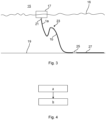
- Fig. 3 shows an offshore structure 15 comprising a floating platform 17 that floats on water 16, and the dynamic submarine power cable 1.
- the floating platform 17 may for example be the floating platform of a floating wind turbine, or a semi-submersible platform for oil and gas applications.
- the dynamic submarine power cable 1 is suspended from the floating platform 17 and extends down to the seabed 19.
- the offshore structure 15 comprises a bend stiffener 21, or alternatively a Bellmouth, connected to the floating platform 17, which is arranged around a top portion of the dynamic submarine power cable 1.
- the bend stiffener 21, or Bellmouth is arranged around a top section 1a of the dynamic submarine power cable 1.
- the first section 8a of the metallic water blocking layer 7 is arranged along the top section 1a of the dynamic submarine power cable 1 as the dynamic submarine power cable 1 hangs from the floating platform 17 and extends to the seabed 19.
- the first section 8a maybe at least 50 m long, such as at least 100 m long, such as at least 150 m long, such as at least 200 m long.
- the first section 8a maybe at most 800 m long, such as at most 600 m long, such as at most 400 m long.
- the dynamic submarine power cable 1 may be provided with buoyance modules 23 to provide a wave configuration to the dynamic submarine power cable 1 as it extends towards the seabed 19.
- the dynamic submarine power cable 1 could alternatively be free hanging from the floating platform 17.
- the dynamic submarine power cable 1 has a bottom section 1b which, like the first section 8a, is arranged hanging in the water column between the floating platform 17 and the seabed 19.
- the second section 8b is arranged along the bottom section 1b of the dynamic submarine power cable 1.
- the second section 8b may according to one example be at least 100 m long, such as at least 200 m long.
- the second section 8b may according to one example be at most 3000 m or at most 5000 m long. Generally, the length of the second section 8b depends on the water depth.
- a portion of the bottom section 1b and thus of the second section 8b extends to the seabed 19 and may extend along the seabed 19 to a joint 27 on the seabed 19, which connects the dynamic submarine power cable 1 to a static submarine power cable 27.
- a dynamic submarine power cable such as the dynamic submarine power cable 1
- the first section 8a and the second section 8b is produced in one length.
- the insulation system 5 may be made in one length along the entire length of the dynamic submarine power cable 1. Thus, in this example, no factory joints which joint the insulation system 5 are made.
- a metal tube is first arranged around the insulation system 5.
- the metal tube may be made by folding a metal sheath around the insulation system 5 and longitudinally welding, soldering, or gluing of the metal sheath.
- the first section 8a and the second section 8b are produced in two separate lengths and then jointed.
- the dynamic submarine power cable 1, or more typically, the one or more power cores of the submarine power cable 1, may typically also be produced in two lengths that are jointed.
- a step a) the metal tube arranged around an insulation system 5 is corrugated to form the corrugated metallic water blocking layer 7a.
- step a) the first section 8a of the metallic water blocking layer 7 is produced.
- Step a) is carried out by a corrugation machine through which at least that part or portion of the dynamic submarine power cable 1 for which the metal tube is corrugated passes.
- a diameter reduction of the metal tube arranged around an insulation system 5 is performed to form the smooth metallic water blocking layer 7b.
- Step b) is carried out by a roller assembly through which the second section 8b of the dynamic submarine power cable 1 passes.
- step b) the second section 8b of the metallic water blocking layer 7 is produced.
- Step a) may be carried out before step b), or step b) may be carried out before step a). If the first section 8a and the second section 8b are physically separate lengths of the metallic water blocking layer 7 during steps a) and b), steps a) and b) may be carried out simultaneously in case the factory provides for such production possibilities.
- the corrugated metallic water blocking layer 7a and the smooth dynamic metallic water blocking layer 7b forms the metallic water blocking layer 7, which in this case may be made in one length in the region where it transitions from being corrugated to being smooth.
- the first section 8a and the second section 8b have to be jointed after steps a) and b) have been carried out.
- the jointing may involve jointing the conductor 3, the insulation system 5, and the corrugated metallic water blocking layer 7a and the smooth metallic water blocking layer 7b.
- the jointing of the corrugated metallic water blocking layer 7a and the smooth metallic water blocking layer 7b may for example be done by soldering or welding.
- only a portion of one of the metal tubes is corrugated.
- the remaining length of this metal tube may be made smooth by subjecting it to diameter reduction, and the smooth portion may be jointed with the smooth metallic water blocking layer 7b made in step b).
Landscapes
- Engineering & Computer Science (AREA)
- Manufacturing & Machinery (AREA)
- Ocean & Marine Engineering (AREA)
- Architecture (AREA)
- Civil Engineering (AREA)
- Structural Engineering (AREA)
- Chemical & Material Sciences (AREA)
- Combustion & Propulsion (AREA)
- Mechanical Engineering (AREA)
- Insulated Conductors (AREA)
- Laying Of Electric Cables Or Lines Outside (AREA)
Priority Applications (5)
| Application Number | Priority Date | Filing Date | Title |
|---|---|---|---|
| EP22199612.7A EP4350717A1 (fr) | 2022-10-04 | 2022-10-04 | Câble d'alimentation sous-marin dynamique à barrière d'eau métallique ondulée et lisse |
| US18/473,452 US20240112832A1 (en) | 2022-10-04 | 2023-09-25 | Dynamic Submarine Power Cable With Corrugated And Smooth Metallic Water Barrier |
| KR1020230130967A KR20240047320A (ko) | 2022-10-04 | 2023-09-27 | 주름지고 매끄러운 금속 수방벽을 갖춘 동적 해저 전력 케이블 |
| JP2023169040A JP2024054085A (ja) | 2022-10-04 | 2023-09-29 | 波形および平滑金属製水バリアを有する動的海底電力ケーブル |
| CA3215205A CA3215205A1 (fr) | 2022-10-04 | 2023-10-03 | Cable d'alimentation sous-marin dynamique comprenant une barriere d'etancheite metallique ondulee et lisse |
Applications Claiming Priority (1)
| Application Number | Priority Date | Filing Date | Title |
|---|---|---|---|
| EP22199612.7A EP4350717A1 (fr) | 2022-10-04 | 2022-10-04 | Câble d'alimentation sous-marin dynamique à barrière d'eau métallique ondulée et lisse |
Publications (1)
| Publication Number | Publication Date |
|---|---|
| EP4350717A1 true EP4350717A1 (fr) | 2024-04-10 |
Family
ID=83594029
Family Applications (1)
| Application Number | Title | Priority Date | Filing Date |
|---|---|---|---|
| EP22199612.7A Pending EP4350717A1 (fr) | 2022-10-04 | 2022-10-04 | Câble d'alimentation sous-marin dynamique à barrière d'eau métallique ondulée et lisse |
Country Status (5)
| Country | Link |
|---|---|
| US (1) | US20240112832A1 (fr) |
| EP (1) | EP4350717A1 (fr) |
| JP (1) | JP2024054085A (fr) |
| KR (1) | KR20240047320A (fr) |
| CA (1) | CA3215205A1 (fr) |
Families Citing this family (1)
| Publication number | Priority date | Publication date | Assignee | Title |
|---|---|---|---|---|
| CN118970799A (zh) * | 2024-08-30 | 2024-11-15 | 中天科技海缆股份有限公司 | 适用于浅海域的水下动态海缆系统 |
Citations (2)
| Publication number | Priority date | Publication date | Assignee | Title |
|---|---|---|---|---|
| JP2014032912A (ja) * | 2012-08-06 | 2014-02-20 | Furukawa Electric Co Ltd:The | 疲労特性に優れた海中ケーブルおよびその遮水層用複層テープ |
| EP2896053A1 (fr) | 2012-09-14 | 2015-07-22 | ABB Research Ltd. | Barrière radiale contre l'eau et câble sous-marin haute tension dynamique pour applications en eau profonde |
Family Cites Families (36)
| Publication number | Priority date | Publication date | Assignee | Title |
|---|---|---|---|---|
| FR2741696B1 (fr) * | 1995-11-29 | 1998-01-02 | Coflexip | Raidisseur pour une canalisation flexible a usage en milieu marin |
| US5760334A (en) * | 1996-07-24 | 1998-06-02 | Alcatel Kabel Ag & Co. | Metallic sheath for an electric cable and method of making the same |
| US7936957B1 (en) * | 2007-03-09 | 2011-05-03 | Superior Essex Communications, Lp | High-density fiber optic ribbon cable with enhanced water blocking performance |
| US7590322B2 (en) * | 2007-03-09 | 2009-09-15 | Superior Essex Communications Lp | Fiber optic cable with enhanced saltwater performance |
| CN102483989B (zh) * | 2009-07-03 | 2014-02-19 | 瑞士单浮筒系泊公司 | 高压电感应旋转装置 |
| EP2312591B1 (fr) * | 2009-08-31 | 2020-03-04 | Nexans | Barrière métallique contre l'humidité résistant à la fatigue dans un câble d'alimentation sous-marin |
| EP2750144B1 (fr) * | 2011-08-23 | 2017-08-09 | Furukawa Electric Co., Ltd. | Câble sous-marin, ruban multicouche destiné à une couche de blindage contre l'eau d'un câble sous-marin, et procédé permettant d'améliorer les caractéristiques de fatigue d'un câble sous-marin |
| JP5987208B2 (ja) * | 2012-08-20 | 2016-09-07 | 矢崎総業株式会社 | ワイヤハーネス用外装部材及びワイヤハーネス |
| GB2505660B (en) * | 2012-09-05 | 2014-12-03 | Bpp Cables Ltd | Subsea cables |
| US9424963B1 (en) * | 2012-12-12 | 2016-08-23 | Superior Essex Communications Lp | Moisture mitigation in premise cables |
| EP3014632B1 (fr) * | 2013-06-27 | 2017-05-24 | Prysmian S.p.A. | Procédé de fabrication de câbles électriques et câble électrique associé |
| JP5984066B2 (ja) * | 2013-08-02 | 2016-09-06 | 住友電装株式会社 | シールド導電路 |
| EP3084779B1 (fr) * | 2013-12-19 | 2017-09-27 | NKT HV Cables GmbH | Agencement pour un câble sous-marin à haute tension dynamique et câble sous-marin à haute tension dynamique |
| DE102014206000A1 (de) * | 2014-03-31 | 2015-10-01 | Siemens Aktiengesellschaft | Kühlvorrichtung |
| DE102015209432A1 (de) * | 2015-05-22 | 2016-11-24 | Siemens Aktiengesellschaft | Vorrichtung zur Gleichstromübertragung und Kühlverfahren |
| EP3358574A4 (fr) * | 2015-09-30 | 2019-08-21 | LS Cable & System Ltd. | Câble sous-marin à blindage hétérogène |
| GB2552370A (en) * | 2016-07-21 | 2018-01-24 | Jdr Cable Systems Ltd | Insulated cable |
| US10264711B2 (en) * | 2016-11-30 | 2019-04-16 | Data Marine, LLC | Data vessel integrated with cooling and docking station with ancillary service |
| DE102017108389B4 (de) * | 2017-04-20 | 2026-02-12 | Leoni Kabel Gmbh | Barriereschicht gegen Migration eines Stoffes, elektrischer Leiter, Verfahren zum Fertigen eines beschichteten Kabels und Verwendung von Polyethylenfuranoat als Barriereschicht |
| EP3438993B1 (fr) * | 2017-08-02 | 2021-10-06 | Nexans | Câble de puissance dynamique |
| CA3100991A1 (fr) * | 2018-05-25 | 2019-11-28 | Prysmian S.P.A. | Cable d'alimentation haute tension dote d'une barriere a l'eau resistante a la fatigue |
| DE102018125323A1 (de) * | 2018-10-12 | 2020-04-16 | Innogy Se | Windkraftanlage |
| EP3786982B1 (fr) * | 2019-08-26 | 2023-06-07 | Nexans | Gaine de câble en alliage cunisi |
| WO2021050324A1 (fr) * | 2019-09-13 | 2021-03-18 | Commscope Technologies Llc | Câble hybride pour une connectivité électrique distribuée |
| IT201900016406A1 (it) * | 2019-09-16 | 2021-03-16 | Prysmian Spa | Processo per produrre un cavo di potenza sottomarino e cavo di potenza cosi’ prodotto. |
| EP3839981A1 (fr) * | 2019-12-19 | 2021-06-23 | NKT HV Cables AB | Câble électrique sous-marin ca avec réduction des pertes |
| JP7384095B2 (ja) * | 2020-03-27 | 2023-11-21 | 住友電装株式会社 | ワイヤハーネス |
| EP4068309A1 (fr) * | 2021-03-29 | 2022-10-05 | Nexans | Gaine en pe à faible résistance ayant des propriétés adhésives et mécaniques combinées |
| GB202104947D0 (en) * | 2021-04-07 | 2021-05-19 | Advanced Insulation Ltd | Retaining element |
| US12030597B2 (en) * | 2021-07-22 | 2024-07-09 | Chevron U.S.A. Inc. | High voltage submarine cable systems |
| DE102021131422A1 (de) * | 2021-11-30 | 2023-06-01 | Rwe Renewables Gmbh | Seekabelsystem und Verfahren zum Verlegen eines Seekabelsystems |
| NO347780B1 (en) * | 2021-12-03 | 2024-03-25 | Kongsberg Maritime As | Pull-in of dynamic cables for floating wind turbines |
| EP4243038B1 (fr) * | 2022-03-10 | 2026-02-18 | Nexans | Matériaux formant barrière à l'eau pour un câble d'alimentation dynamique destiné aux applications sous-marines |
| IT202200006962A1 (it) * | 2022-04-07 | 2023-10-07 | Prysmian Spa | Cavo di alimentazione o di trasmissione dati con barriera metallica per l’acqua e processo di fabbricazione di tale cavo. |
| US20240021342A1 (en) * | 2022-07-18 | 2024-01-18 | RSCC Wire and Cable LLC | Cable Substitute for Mineral-Insulated Cables in Nuclear Facilities |
| EP4345851A1 (fr) * | 2022-09-30 | 2024-04-03 | NKT HV Cables AB | Câble d'alimentation sous-marin avec additif de glissement |
-
2022
- 2022-10-04 EP EP22199612.7A patent/EP4350717A1/fr active Pending
-
2023
- 2023-09-25 US US18/473,452 patent/US20240112832A1/en active Pending
- 2023-09-27 KR KR1020230130967A patent/KR20240047320A/ko active Pending
- 2023-09-29 JP JP2023169040A patent/JP2024054085A/ja active Pending
- 2023-10-03 CA CA3215205A patent/CA3215205A1/fr active Pending
Patent Citations (3)
| Publication number | Priority date | Publication date | Assignee | Title |
|---|---|---|---|---|
| JP2014032912A (ja) * | 2012-08-06 | 2014-02-20 | Furukawa Electric Co Ltd:The | 疲労特性に優れた海中ケーブルおよびその遮水層用複層テープ |
| EP2896053A1 (fr) | 2012-09-14 | 2015-07-22 | ABB Research Ltd. | Barrière radiale contre l'eau et câble sous-marin haute tension dynamique pour applications en eau profonde |
| US20150248951A1 (en) * | 2012-09-14 | 2015-09-03 | Abb Research Ltd | Radial water barrier and a dynamic high voltage submarine cable for deep water applications |
Non-Patent Citations (2)
| Title |
|---|
| RESNER LESZEK ET AL: "Radial Water Barrier in Submarine Cables, Current Solutions and Innovative Development Directions", ENERGIES, vol. 14, no. 10, 12 May 2021 (2021-05-12), pages 2761, XP055958440, DOI: 10.3390/en14102761 * |
| WEERHEIM RUBEN: "Development of dynamic power cables for commercial floating wind farms", REPORT LITERATURE ASSIGNMENT, 12 November 2018 (2018-11-12), XP055794185, Retrieved from the Internet <URL:https://repository.tudelft.nl/islandora/object/uuid%3A487ba1e5-2764-4e96-808c-a9ee2772219d> [retrieved on 20210412] * |
Also Published As
| Publication number | Publication date |
|---|---|
| CA3215205A1 (fr) | 2024-04-04 |
| US20240112832A1 (en) | 2024-04-04 |
| KR20240047320A (ko) | 2024-04-12 |
| JP2024054085A (ja) | 2024-04-16 |
Similar Documents
| Publication | Publication Date | Title |
|---|---|---|
| EP3098820B1 (fr) | Câble sous-marin, structure d'installation pour câble sous-marin, et procédé d'installation d'un câble sous-marin | |
| US10056171B2 (en) | Submarine cable and multilayer tape for impermeable layer of same | |
| KR101457330B1 (ko) | 해중 케이블, 그 차수층용 복층 테이프 및 해중 케이블의 피로특성 향상방법 | |
| US9029704B2 (en) | Electric power cable | |
| GB2511152A (en) | Electric submersible pump cables for harsh environments | |
| US12431696B2 (en) | Rigid submarine power cable joint | |
| US20240112832A1 (en) | Dynamic Submarine Power Cable With Corrugated And Smooth Metallic Water Barrier | |
| Leroy et al. | Assessing mechanical stresses in dynamic power cables for floating offshore wind farms | |
| AU2013407859B2 (en) | An arrangement for a dynamic high voltage subsea cable and a dynamic high voltage subsea cable | |
| JP5323973B1 (ja) | 疲労特性に優れた海中ケーブルおよびその遮水層用複層テープ | |
| WO2025073893A1 (fr) | Câble d'alimentation de transmission sous-marin | |
| US20240355506A1 (en) | Dynamic Submarine Power Cable System with Bend Restriction Device | |
| US11450455B2 (en) | Electrical cable for vertical applications | |
| KR20260035783A (ko) | 동적 고전압 해저 케이블 및 동적 고전압 해저 케이블을 제조하는 방법 | |
| EP4517784A1 (fr) | Procédé de fabrication d'un câble sous-marin dynamique avec une couche de frottement élevée | |
| WO2025073889A1 (fr) | Système de production d'énergie en mer | |
| WO2025073891A1 (fr) | Câble d'alimentation de transmission sous-marin | |
| JP2025137446A (ja) | 海底dc電力ケーブル |
Legal Events
| Date | Code | Title | Description |
|---|---|---|---|
| PUAI | Public reference made under article 153(3) epc to a published international application that has entered the european phase |
Free format text: ORIGINAL CODE: 0009012 |
|
| STAA | Information on the status of an ep patent application or granted ep patent |
Free format text: STATUS: THE APPLICATION HAS BEEN PUBLISHED |
|
| AK | Designated contracting states |
Kind code of ref document: A1 Designated state(s): AL AT BE BG CH CY CZ DE DK EE ES FI FR GB GR HR HU IE IS IT LI LT LU LV MC ME MK MT NL NO PL PT RO RS SE SI SK SM TR |
|
| STAA | Information on the status of an ep patent application or granted ep patent |
Free format text: STATUS: REQUEST FOR EXAMINATION WAS MADE |
|
| 17P | Request for examination filed |
Effective date: 20241010 |
|
| RBV | Designated contracting states (corrected) |
Designated state(s): AL AT BE BG CH CY CZ DE DK EE ES FI FR GB GR HR HU IE IS IT LI LT LU LV MC ME MK MT NL NO PL PT RO RS SE SI SK SM TR |
|
| STAA | Information on the status of an ep patent application or granted ep patent |
Free format text: STATUS: EXAMINATION IS IN PROGRESS |