EP4350721B1 - Magnetischer stromsensor, mischstromsensor mit einem solchen magnetischen stromsensor und schutzschalter mit einem solchen mischstromsensor - Google Patents
Magnetischer stromsensor, mischstromsensor mit einem solchen magnetischen stromsensor und schutzschalter mit einem solchen mischstromsensor Download PDFInfo
- Publication number
- EP4350721B1 EP4350721B1 EP23198161.4A EP23198161A EP4350721B1 EP 4350721 B1 EP4350721 B1 EP 4350721B1 EP 23198161 A EP23198161 A EP 23198161A EP 4350721 B1 EP4350721 B1 EP 4350721B1
- Authority
- EP
- European Patent Office
- Prior art keywords
- current sensor
- coil
- main body
- magnetic
- connection pin
- Prior art date
- Legal status (The legal status is an assumption and is not a legal conclusion. Google has not performed a legal analysis and makes no representation as to the accuracy of the status listed.)
- Active
Links
Images


Classifications
-
- G—PHYSICS
- G01—MEASURING; TESTING
- G01R—MEASURING ELECTRIC VARIABLES; MEASURING MAGNETIC VARIABLES
- G01R15/00—Details of measuring arrangements of the types provided for in groups G01R17/00 - G01R29/00, G01R33/00 - G01R33/26 or G01R35/00
- G01R15/14—Adaptations providing voltage or current isolation, e.g. for high-voltage or high-current networks
- G01R15/18—Adaptations providing voltage or current isolation, e.g. for high-voltage or high-current networks using inductive devices, e.g. transformers
- G01R15/181—Adaptations providing voltage or current isolation, e.g. for high-voltage or high-current networks using inductive devices, e.g. transformers using coils without a magnetic core, e.g. Rogowski coils
-
- G—PHYSICS
- G01—MEASURING; TESTING
- G01R—MEASURING ELECTRIC VARIABLES; MEASURING MAGNETIC VARIABLES
- G01R15/00—Details of measuring arrangements of the types provided for in groups G01R17/00 - G01R29/00, G01R33/00 - G01R33/26 or G01R35/00
- G01R15/14—Adaptations providing voltage or current isolation, e.g. for high-voltage or high-current networks
- G01R15/20—Adaptations providing voltage or current isolation, e.g. for high-voltage or high-current networks using galvano-magnetic devices, e.g. Hall-effect devices, i.e. measuring a magnetic field via the interaction between a current and a magnetic field, e.g. magneto resistive or Hall effect devices
- G01R15/207—Constructional details independent of the type of device used
-
- G—PHYSICS
- G01—MEASURING; TESTING
- G01R—MEASURING ELECTRIC VARIABLES; MEASURING MAGNETIC VARIABLES
- G01R19/00—Arrangements for measuring currents or voltages or for indicating presence or sign thereof
- G01R19/0092—Measuring current only
-
- H—ELECTRICITY
- H01—ELECTRIC ELEMENTS
- H01F—MAGNETS; INDUCTANCES; TRANSFORMERS; SELECTION OF MATERIALS FOR THEIR MAGNETIC PROPERTIES
- H01F27/00—Details of transformers or inductances, in general
- H01F27/02—Casings
-
- H—ELECTRICITY
- H01—ELECTRIC ELEMENTS
- H01F—MAGNETS; INDUCTANCES; TRANSFORMERS; SELECTION OF MATERIALS FOR THEIR MAGNETIC PROPERTIES
- H01F38/00—Adaptations of transformers or inductances for specific applications or functions
- H01F38/20—Instruments transformers
- H01F38/22—Instruments transformers for single phase AC
- H01F38/28—Current transformers
- H01F38/30—Constructions
-
- H—ELECTRICITY
- H02—GENERATION; CONVERSION OR DISTRIBUTION OF ELECTRIC POWER
- H02H—EMERGENCY PROTECTIVE CIRCUIT ARRANGEMENTS
- H02H3/00—Emergency protective circuit arrangements for automatic disconnection directly responsive to an undesired change from normal electric working condition with or without subsequent reconnection ; integrated protection
- H02H3/08—Emergency protective circuit arrangements for automatic disconnection directly responsive to an undesired change from normal electric working condition with or without subsequent reconnection ; integrated protection responsive to excess current
Definitions
- the present invention relates to a magnetic current sensor. It also relates to a mixed current sensor, comprising such a magnetic current sensor. It also relates to a circuit breaker comprising such a mixed current sensor.
- Magnetic current sensors are current transformers that provide a secondary supply current from a primary current. These magnetic current sensors typically comprise a magnetic circuit, through which an electrical conductor forming the primary circuit passes, and an electrical winding, which is wound around a portion of the magnetic circuit and at the ends of which the secondary current is available. Such a magnetic current sensor can be used in particular in a mixed current sensor where, in addition to passing through the magnetic circuit of the magnetic current sensor, the electrical conductor forming the primary circuit passes through a Rogowski coil whose ends are connected to an electronic circuit for acquiring and measuring the primary current, i.e. the electrical current flowing in the electrical conductor forming the primary circuit, this electronic circuit being powered by the winding of the magnetic current sensor.
- Such mixed current sensors are used in particular in high-power circuit breakers whose opening is controlled by the aforementioned electronic circuit.
- FR 2 990 759 A1 discloses for example such a mixed current sensor, the magnetic sensor of which includes an electric winding, without the arrangements relating to the connection of the two ends of this winding being detailed.
- the invention relates more specifically to magnetic current sensors in which an insulating coil is interposed between the magnetic circuit, the aforementioned portion of which is received inside the coil, and the winding, which is wound on the coil.
- This coil supports two connection pins, which are respectively connected to the ends of the winding and which make it possible to connect electrical elements to conduct the current supplied by the winding to a load to be powered, such as the aforementioned electronic circuit.
- the mounting of these connection pins on the coil must take into account significant constraints linked to the various assembly operations of the magnetic current sensor, in particular the soldering operations between the connection pin and, on the one hand, the ends of the winding and, on the other hand, the electrical elements connecting the connection pin to the load to be powered.
- the connection pins are generally mounted on the coil simply by mechanical interference, typically by wedging/clipping.
- connection pins can be the cause of failures leading to the breaking of the connection between the winding and the load to be supplied, the consequences of which can be particularly serious when the magnetic sensor of current is integrated into a high-power circuit breaker. Indeed, in service, magnetic current sensors may be subjected to operating temperatures and/or operating vibrations such that the connection pins may gradually become detached from the coil, until the winding wire breaks, and/or shears a portion of the winding wire, arranged across an edge of the connection pins.
- the attachment of the connection pins to the coil can be reinforced by glue or resin, which is applied so as to coat together each of the connection pins and the part of the coil where this connection pin is mounted. This solution is effective but is not completely satisfactory, particularly from an environmental and repeatability point of view.
- the aim of the present invention is to propose an improved magnetic current sensor, the mounting of the connection pins on the coil of which is robust, reliable and controlled.
- the invention relates to a magnetic current sensor, as defined in claim 1.
- the invention provides for integrating into each connection pin two tabs projecting from the main body of the connection pin, which are folded against a side wall of the housing that the coil delimits to receive this main body, this folding being designed to lock the main body in position in the housing and therefore hold the connection pin in place relative to the coil.
- the folded conformation of the tabs allows them to make the mounting of the connection pin on the coil robust and reliable, while preventing them from extending across the interior of the coil, where a portion of the magnetic circuit is received.
- the locked mounting of the connection pin on the coil withstands common operating conditions when the magnetic current sensor is used in a high-power circuit breaker, in particular by resisting temperatures of the order of 150°C and vibrations under 8g.
- the solution of the invention thus proves to be particularly practical and effective, without requiring modification or adaptation of the magnetic circuit and the winding, and it is simple to implement, in particular by including in the assembly operations of the magnetic current sensor according to the invention an operation of folding the tabs and then, if necessary, an operation of cutting/shaving the tabs at their free end.
- each pin of connection can advantageously integrate, apart from the two tabs, arrangements making it possible to further reinforce the attachment to the coil and/or to effectively operate the electrical connection with the winding and with a track connecting the connection pin to a load and/or to avoid extending the connection pin into a region outside the housing where it risks shearing the winding wire.
- the invention also relates to a circuit breaker, as defined in claim 14.
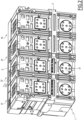
- Circuit breaker 1 is typically a high-power circuit breaker, particularly high-intensity in the sense that, in the normally closed state of circuit breaker 1, circuit breaker 1 allows the circulation through it of a permanent current, direct or alternating, the intensity of which is between a few hundred and a few thousand amperes, particularly between 500A and 7500A.
- the circuit breaker 1 is here multipolar, being intended to be used in an electrical circuit comprising several electrical poles.
- the circuit breaker 1 has four independent poles P1, P2, P3 and P4.
- the circuit breaker 1 has a different number of poles, for example 2 or 3.
- the circuit breaker 1 has only one pole.
- the circuit breaker 1 has an insulating casing 2, which supports the poles P1 to P4.
- the casing 2 is, for example, made of a plastic material.
- the casing 2 delimits an internal volume, which is essentially closed and which, here, is divided into four separate compartments, respectively associated with the poles P1 to P4.
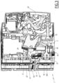
- poles P1 to P4 being identical to the other poles, only one of them is described in detail below, namely pole P2 which is shown in section on the Figure 3
- pole P2 which is shown in section on the Figure 3
- the description given for pole P2 applies to each of the other poles P1, P3 and P4.
- the pole P2 comprises two terminal pads 10 and 11 which allow the pole P2 to be connected to an electrical circuit to be protected by the circuit breaker 1.
- the terminal pads 10 and 11, which are made of an electrically conductive material, generally a metal such as copper, are carried by the casing 2 so as to be electrically connectable from the outside of the casing 2 to the electrical circuit to be protected.
- the terminal pads 10 and 11 pass through a dedicated wall of the casing 2, emerging, on either side of this dedicated wall, outside the casing 2 and inside the casing 2, in other words in the internal volume of the latter, more precisely inside the compartment of this internal volume, associated with the pole P2.
- Pole P2 also comprises two contact elements 20 and 21 which are respectively connected to the terminal pads 10 and 11 while being movable relative to each other between a closed position, which is not shown, and an open position, which is shown in the Figure 3 .
- the contact elements 20 and 21 are in direct contact with each other and allow the flow of an electric current between the terminal pads 10 and 11.
- the contact elements 20 and 21 are spaced apart from each other and interrupt the electric flow between the terminal pads 10 and 11.
- the contact element 20 is fixedly carried by a movable arm 23 which is electrically connected to the terminal pad 10, while the contact element 21 is fixedly carried by the terminal pad 11 which is itself fixedly carried by the casing 2.
- the contact elements 20 and 21 are arranged in an extinguishing chamber 24 associated with the pole P2.
- the extinguishing chamber 24 is delimited inside the casing 2, thus forming a part of the internal volume of the latter, more precisely a part of the compartment of this internal volume, associated with the pole P2.
- the extinguishing chamber 24 is filled with air and surrounds the contact elements 20 and 21 so as to promote the extinction of the electric arc forming between the contact elements 20 and 21 when the latter pass from their closed position to their open position.
- the electric arc ionizes the air present in the extinguishing chamber 24, which generates gases, called cutting gases, which are partially ionized and which contain suspended particles, such as soot and/or metal particles.
- the formation of this electric arc creates in the cutting chamber 24 an overpressure which must be supported by the parts of the casing 2, delimiting the cutting chamber 24, and by the components of the circuit breaker 1, arranged in the cutting chamber 24.
- Pole P2 also includes a mechanism 30 for opening the circuit breaker 1, i.e. for moving the contact elements 20 and 21 from the closed position to the open position, when an operating anomaly is detected.
- the operating anomaly is for example an overload, a short circuit or an overcurrent of the electric current flowing in the circuit to be protected by the circuit breaker 1, for at least one of the poles P1 to P4.
- the detection of this operating anomaly is ensured by the circuit breaker 1 itself, as explained in more detail below.
- the mechanism 30 is arranged inside the enclosure 2, more precisely in the compartment of the internal volume of the latter, associated with pole P2. In practice, the mechanism 30 is known per se in the field and will therefore not be described further here. In other words, the specific features of the mechanism 30 are not limiting.
- the mechanism 30 is designed to set the movable arm 23 in motion in order to move the contact elements 20 and 21 between their closed and open positions.
- the mechanism 30 is advantageously designed to, when it moves the contact elements 20 and 21 from their closed position to their open position, cause the contact elements of the other poles P1, P3 and P4 of the circuit breaker 1 to open, in particular by means of mechanisms, similar to the mechanism 30 of the pole P2, which belong respectively to the poles P1, P3 and P4.
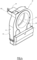
- Pole P2 also has a mixed current sensor 40, which is visible at the Figure 3 and which is represented alone on the figures 4 to 6 .
- the mixed current sensor 40 is arranged inside the casing 2, more precisely in the compartment of the internal volume of the latter, associated with the pole P2, being arranged in the cutting chamber 24.
- the mixed current sensor 40 comprises a housing 41 which is crossed by a passage 42 along a passage axis X42 on which the passage 42 is centered.
- the terminal stud 10 is received, here in a complementary manner, in the passage 42, extending parallel to the passage axis X42, or even, as here, being aligned with the passage axis X42.
- the housing 41 is thus crossed, via its passage 42, by the terminal stud 10, and is arranged in the breaking chamber 24 by being arranged, along the passage axis X42, against a part of the casing 2, which is also crossed by the terminal stud 10 along the passage axis X42.
- the housing 41 also delimits an internal volume 43 which is separated from the passage 42, by surrounding the passage 42 all around the passage axis X42.
- the housing 41 comprises for this purpose a shell 44 and a cover 45 which is fixedly assembled to the shell 44 by closing it so as to delimit the internal volume 43 between the shell 44 and the cover 45.
- Other embodiments are conceivable for the housing 41.
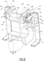
- the mixed current sensor 40 also comprises a magnetic current sensor 50, a current measuring device 60 and an electronic circuit 70, which will be described in more detail below and which are all housed in the internal volume 43 of the housing 41 in the assembled state of the mixed current sensor 40.
- the magnetic current sensor 50 comprises a magnetic circuit 51 which is arranged in the internal volume 43 of the housing 41 so as to surround the passage 42.
- the magnetic circuit 51 comprises several metal plates 510 stacked in direct contact with each other in a direction parallel to the passage axis X42, these metal plates 510 being traversed, right through their stack, by the passage 42.
- Other embodiments are conceivable for the magnetic circuit 51.
- the current measuring device 60 comprises a Rogowski coil 61 which is arranged in the internal volume 43 of the housing 41 so as to surround the passage 42.
- the Rogowski coil 61 comprises a metallic electric wire 62, which is not shown in detail in the figures and which is for example made of copper or a copper-based alloy.
- the electric wire 62 is wound on an insulating carcass 63, made of a non-magnetic material.
- the carcass 63 surrounds the passage 62 all around the passage axis X42 and, here, has a generally annular shape with a circular base, centered on the passage axis X42.
- Other embodiments are possible for the Rogowski winding 61.
- the magnetic circuit 51 of the magnetic current sensor 50 and the Rogowski coil 61 of the current measuring device 60 are designed to, in service, surround the same electrical conductor forming a primary circuit for each of them, that is to say a primary circuit for the magnetic circuit 51 and a primary circuit for the Rogowski coil 61, this electrical conductor passing through the mixed current sensor 40 through the passage 42 of its housing 41.
- the electrical conductor forming a primary circuit for the magnetic circuit 51 and for the Rogowski coil 61 is constituted by the terminal stud 10 which, in the assembled state of the circuit breaker 1, is received in the passage 42 and is thus surrounded, all around the passage axis X42, by both the magnetic circuit 51 and the Rogowski coil 61.
- Rogowski 61 as shown in the Figure 3 .
- the Rogowski coil 61 is connected to the electronic circuit 70 for the purpose of processing by the latter the electric current flowing in the Rogowski coil 61.
- the embodiment of the connection between the Rogowski coil 61 and the electronic circuit 70 is not limiting.
- the current measuring device 60 comprises for this purpose a connection cassette 64 which, while ensuring the electrical connection between the ends of the Rogowski coil 61 and the terminals of the electronic circuit 70, makes it possible to ensure the relative fixing and positioning between the Rogowski coil 61 and the electronic circuit 70 in the housing 41.
- the connection cassette 64 extends from the Rogowski coil 61 into a dedicated housing of the internal volume 43, at the bottom of which the electronic circuit 70 is arranged and which is here closed by an attached cover 46 of the housing 41.
- the latter is configured to, from the electric current flowing in the Rogowski winding 61, detect and measure the electric current flowing in the electrical conductor forming the primary circuit of the Rogowski winding 61, in other words, here, to detect and measure the electric current in the terminal pad 10 in the assembled state of the circuit breaker 1.
- the current flowing in the Rogowski winding 61 provides a measurement signal representative of the electric current flowing in the terminal pad 10, the electronic circuit 70 being designed to process this measurement signal.
- the voltage across the Rogowski winding 61 is directly proportional to the intensity of the electric current in the terminal pad 10.
- the electronic means for acquiring and measuring the current which belong to the electronic circuit 70, are known per se in the field and will not be described here further, the embodiment of these electronic means not being limiting.
- the electronic circuit 70 is here designed to control the mechanism 30 of the circuit breaker 1, by sending it an activation signal when the processing carried out by the electronic circuit 70 reveals the operating anomaly previously mentioned.
- the mechanism 30 is controlled by the electronic circuit 70 to move the contact elements 20 and 21 from their closed position to their open position.
- the magnetic current sensor 50 comprises, in addition to its magnetic circuit 51, an electrical winding 52.
- this winding 52 is not shown in the figures 3 , 5 , 6 And 10 and is only partially and schematically represented on the figures 7 to 9
- the winding 52 is made of a metal wire, preferably made of copper or a copper-based alloy, which is wound around a portion 511 of the magnetic circuit 51, with the interposition of an insulating coil 53, belonging to the magnetic current sensor 50.
- the portion 511 of the magnetic circuit 51 which is indicated in dotted lines on the Figure 7 , is here offset from the passage 42 relative to the passage axis X42, being constituted by the part of the magnetic circuit 51, which is the furthest from the passage 42.
- the winding 52 includes two ends 520 and 521, which are respectively only shown on the figures 8 And 9 and which are respectively constituted by the opposite ends of the metal wire constituting this winding.
- the winding 52 also includes a wound running part 522, which is shown schematically only on the Figure 7 and which connects ends 520 and 521 to each other.
- the coil 53 which is made of a non-magnetic material, defines a coil axis X53, on which the coil 53 is centered and along which the coil 53 is internally hollow.
- the coil axis X53 extends at a distance and transversely to the passage axis X42, in particular orthogonally to this passage axis X42.
- the coil 53 has a tubular shape, centered on the coil axis X53 and having a square cross-section with rounded corners. Other geometries are conceivable for the coil 53.
- the coil 53 includes two end portions 530 and 531, which are opposite each other along the coil axis X53 and which are connected to each other by an elongated running portion 532 of the coil 53.
- the coil 53 is interposed, radially to the coil axis X53, between the portion 511 of the magnetic circuit 51 and the winding 52.
- the portion 511 of the magnetic circuit 51 is received inside the coil 53, successively extending inside the end portion 530, the elongated running portion 532 and the end portion 531, as well as emerging outside the coil 53 from each of the end portions 530 and 531 along the coil axis X53.
- the winding 52 is wound coaxially with the coil 53, its wound running part 522 being rolled over several turns around and along the elongated running part 532 of the coil 53 and is thus arranged around the portion 511 of the magnetic circuit 51, while the ends 520 and 521 of the winding 52 are arranged, along the coil axis X53, respectively at the level of the end parts 530 and 531 of the coil 53.
- the magnetic current sensor 50 also comprises two connection pins 54 and 55, which are respectively mounted on the end parts 530 and 531 of the coil 53 and which are respectively electrically connected to the ends 520 and 521 of the winding 52.
- the connection pin 54 makes it possible to ensure the electrical connection of the end 520 of the winding 52 while ensuring the fixed mechanical connection of this end 520 of the winding 52 with the end part 530 of the coil 53.
- the connection pin 55 makes it possible to ensure the electrical connection of the end 521 of the winding 52 while ensuring the fixed mechanical connection of this end 521 of the winding 52 with the end part 531 of the coil 53.
- the connection pins 54 and 55 are for this purpose made of a metallic material.
- the magnetic current sensor 50 also comprises two electrical tracks 56 and 57 which respectively connect the connection pins 54 and 55 to a load so that the winding 52 can supply this load.
- the aforementioned load is the electronic circuit 70: thus, in the assembled state of the mixed current sensor 40, the electronic circuit 70 is supplied by the winding 52 via the electrical tracks 56 and 57, as clearly visible on the figures 5 to 10 .
- Each of the electrical tracks 56 and 57 comprises two opposite ends 560 and 561, respectively 570 and 571.
- the end 560 of the electrical track 56, respectively 570 of the electrical track 57 is connected, in particular by soldering, to the connection pin 54, respectively 55, as detailed below in connection with the detailed description of the connection pins 54 and 55.
- the end 561 of the electrical track 56, respectively 571 of the electrical track 57 is connected, in particular by welding, to the electronic circuit 70, the specificities of this connection assembly between the electrical tracks 56 and 57 and the electronic circuit 70 not being limiting.
- connecting pins 54 and 55 are not identical to each other in the sense that they are not interchangeable with each other due to their structural arrangement, which will be detailed below. That being said, the two connecting pins 54 and 55 are functionally similar to each other, being structurally adapted to the terminal portion 530 or 531 of the coil 53, on which they are respectively mounted.
- the connecting pins 54 and 55 are advantageously symmetrical to each other with respect to a geometric plane ⁇ , which is indicated on the Figure 7 and which is perpendicular to the coil axis X53. Therefore, for convenience, the connection pin 54, shown alone in the Figure 11 , it being understood that the description of the connection pin 55 is deduced directly therefrom, in particular by symmetry with respect to the geometric plane ⁇ .
- the connecting pin 54 comprises a main body 540.
- the main body 540 is received in a complementary manner in a housing 533 formed in the end part 530 of the coil 53.
- the housing 533 is closed both by two side walls 533.1 and 533.2, which belong to the end part 530 and which are arranged opposite each other in a direction parallel to the coil axis X53, and by a bottom wall 533.3, which belongs to the end part 530 and which connects to each other, parallel to the coil axis X53, the respective edges, turned towards the coil axis X53, of the side walls 533.1 and 533.2.
- the housing 533 is open between the side walls 533.1 and 533.2 outside the bottom wall 533.3, in particular between the respective edges, facing away from the coil axis X53, of the side walls 533.1 and 533.2.
- the main body 540 has an elongated shape along a body axis X540.
- the body axis X540 extends at a distance and transversely to the coil axis X53, in particular orthogonally to the coil axis X53.
- the connecting pin 54 also has two tabs 541 and 542. As clearly visible on the figures 10 And 11 , the tabs 541 and 542 protrude from the lateral face 540A of the main body 540, running from respective ends 541.1 and 542.1 of junction with the main body 540, to respective free ends 541.2 and 542.2. As clearly visible in the figures 8 , 10 And 11 , the tabs 541 and 542 are spaced apart from each other along the body axis X540.
- the tabs 541 and 542 extend from the lateral face 540A of the main body 540 along respective tab axes X541 and X542, which are parallel to each other and which, in the assembled state of the magnetic current sensor 50, each extend transversely to the coil axis X53 and to the body axis X540, in particular orthogonally to the coil axis X53 and perpendicularly to the body axis X540.
- the tabs 541 and 542 are folded against the same side wall of the housing 533, namely the side wall 533.1, so as to hold the connection pin 54 in position relative to the coil 53.
- each of these tabs 541 and 542 is advantageously folded at 95° ⁇ 5° against the side wall 533.1 of the housing 533. In this way, any unfolding relaxation does not alter the retention in position of the connection pin 55 on the coil 53.
- the retention in position of the connection pin 54 relative to the end portion 530 of the coil 53 by the tabs 541 and 542 is advantageously provided parallel to the tab axes X541 and X542.
- the tabs 541 and 542 are advantageously folded so as to come into contact, in a direction parallel to the tab axes X541 and X542 and oriented opposite the coil axis X53, against the side wall 533.1 of the housing 533, in particular against an edge of this side wall 533.1, facing the coil axis X53. In this way, the tabs 541 and 542 prevent the main body 540 of the connecting pin 54 from coming out of the housing 533 in this direction.
- this lateral face 540A of the main body 540 is advantageously pressed against the bottom wall 533.3 of the housing 533: more precisely, this lateral face 540A of the main body 540 includes bearing surfaces 540A.1, 540A.2 and 540A.3, which are thus pressed against the bottom wall 533.3 and which, as indicated on the Figure 11 , are located on either side, along the body axis X540, of at least one of the tabs 541 and 542, or even, as here, of both tabs 541 and 542. In this way, the connecting pin 54 is effectively stabilized in the bottom of the housing 533 parallel to the tab axes X541 and X542, with functional clearances.
- the retention in position of the connection pin 54 relative to the end portion 530 of the coil 53 by the tabs 541 and 542 is also advantageously provided parallel to the body axis X540.
- the tabs 541 and 542 are advantageously folded so as to come into abutment, in directions which are parallel to the body axis X540 and opposite to each other, against the side wall 533.1 of the housing 533, in particular against parts 533.4 and 533.5 of the side wall 533.1, which project from the edge of the latter facing the coil axis X53, as clearly visible in the figures 8 And 10 .
- the tabs 541 and 542 immobilize the main body 540 in the housing 533 parallel to the body axis X540, and this in the two possible opposite directions.
- connection pin 54 parallel to the coil axis X53, it is advantageously ensured, with clearances, by the side walls 533.1 and 533.2 of the housing 533, the relative spacing of which along the coil axis X53 is substantially equal to the thickness of the main body 540, that is to say to the dimension of the latter between its side faces 540C and 540D.
- the connecting pin 54 includes other features projecting from its main body 540, as detailed below.
- the connecting pin 54 includes an arm 543 which, as clearly visible on the figures 8 , 10 And 11 , extends in an angled manner from the longitudinal end 540.1 of the main body 540, it being noted that the tabs 541 and 542 and this arm 543 are all bent towards the same lateral side of the main body 540, namely that corresponding to its lateral face 540C.
- the arm 543 makes it possible to connect the connecting pin 54 to the electrical track 56: for this purpose, the arm 543 is assembled, in particular by welding, to the electrical track 56, more precisely to the end 560 of the latter.
- the assembly by welding between the arm 543 and the end 560 of the electrical track 56 is advantageously carried out by soldering, for example with a tin solder.
- each of the tabs 541 and 542 is, at its free end 541.2, 542.2, substantially flush with the side wall 533.1 of the housing 533.
- the assembly operations, in particular welding, between the arm 543 and the electrical track 56 are facilitated in the sense that these assembly operations are not hindered by the presence of the tabs 541 and 542 which remain essentially set back from the face of the side wall 533.1, which is turned, along the coil axis X53, on the side where the arm 543 is bent. arm 543.
- the connecting pin 54 includes a mast 544 which, as clearly visible on the figures 8 And 11 , projects from the lateral face 540B of the main body 540.
- This mast 544 is bent towards the longitudinal end 540.2 of the main body 540 so as to extend along the lateral face 540B of the main body 540.
- the mast 544 makes it possible to connect the end 520 of the winding 52 to the connection pin 54.
- the end 520 of the winding 52 is assembled, in particular by welding, around the mast 544, as shown schematically in the figure 8 .
- the end 520 of the winding 52 is wound once or a few times around the mast 544, while being soldered there by brazing, for example with tin solder.
- the connecting pin 54 does not extend, along the body axis X540, from the longitudinal end 540.2 of the main body 540 to the outside of the housing 533, as clearly visible in the figure 8 .
- the connecting pin 54 in particular its main body 540, does not risk interfering with the winding 52, except at the level of the assembly, in particular welded, between the end 520 of the winding 52 and the mast 544: the risks that the connecting pin 54 damages, in particular by shearing, the winding 52 are thus eliminated.
- the lateral face 540B of the main body 540 includes support surfaces 540B.1 and 540B.2 which are located on either side, along the body axis X540, of the mast 544.
- connecting pin 54 applies to the connecting pin 55, taking into account, however, that, on the one hand, the connecting pin 55 is mounted on the terminal part 531 of the coil 533, and not on the terminal part 530 on which the connecting pin 54 is mounted, and, on the other hand, the connecting pin 55 is connected to the end 521 of the winding 52, and not to the end 520 to which the connecting pin 54 is connected, as shown in FIG. Figure 9 .
- the connecting pin 55 comprises a main body 550, two tabs 551 and 552, an arm 553 and a mast 554 which are functionally similar to, respectively, the main body 540, the tabs 541 and 542, the arm 543 and the mast 544, being moreover advantageously respectively symmetrical to the latter with respect to the geometric plane ⁇ .
- the terminal part 531 of the coil 53 is arranged accordingly, in particular by providing a housing 534 which is similar to the housing 533, as clearly visible on the Figure 9 .
- connection pins 54 and 55 have numerous advantages aimed at making the connection of the winding 52 more reliable and reinforcing at the end parts 530 and 531 of the winding 53.
- connection pins 54 and 55 also prove to be particularly easy and practical to assemble to the rest of the magnetic current sensor 50.
- the figures 12 to 14 illustrate three successive moments of assembly operations between the connection pins 54 and 55 and the coil 53.
- the assembly operations relating to the connection pin 54 are described in detail, it being understood that the assembly operations relating to the connection pin 55 are similar.
- the connecting pin 54 with its tabs 541 and 542 and its mast 544 is placed in a not-yet-flexed state, as illustrated in the figures 12 And 13 .
- the tabs 541 and 542 then extend, over their entire extent from their end 541.1, 542.1 of junction with the main body 540, respectively along the tab axes X541 and X542.
- the mast 544 extends, over its entire extent from its end of junction with the main body 540, in a direction parallel to the tab axes X541 and X542.
- the connecting pin 54 is then attached to the terminal part 530 of the coil 53, being introduced into the housing 533 in a direction parallel to the tab axes X541 and X542 and facing the coil axis X53, as indicated by the arrow F1 on the Figure 12 .
- a tool which is applied in the aforementioned direction against the bearing surfaces 540B.1 and 540B.2, as indicated by the arrows F2 on the Figure 12 .
- the tabs 541 and 542 are bent, as indicated by the arrows F3 on the Figure 13 , so as to bend the tabs 541 and 542 against the side wall 533.1 of the housing 533 and thus achieve the assembly conformation of these tabs, described previously in connection with the figures 7 to 11 .
- ad hoc bending tools are used, if necessary partially introduced inside the coil 53.
- the main body 540 is held in place in the housing 533 by applying, along the tab axes X541 and X542, ad hoc tools to the bearing surfaces 540B.1 and 540B.2, as indicated by the arrows F4 on the Figure 13 .
- the tabs 541 and 542 are leveled at their free end 541.2 and 542.2, in order to make these free ends 541.2 and 542.2 substantially flush with the side wall 533.1 of the housing 533, as explained above.
- the mast 544 is bent, advantageously after having been assembled to the end 521 of the winding 52, as explained above.
- the electrical track 56 can be assembled, in particular welded, to the arm 543, as explained above.
- circuit breaker 1 various arrangements and variants of the circuit breaker 1, the mixed current sensor 40, and the magnetic current sensor 50, described so far, are conceivable.
- the different variants mentioned at different points in the description above can be combined with each other, at least partially.
Landscapes
- Engineering & Computer Science (AREA)
- Power Engineering (AREA)
- Physics & Mathematics (AREA)
- General Physics & Mathematics (AREA)
- Measuring Instrument Details And Bridges, And Automatic Balancing Devices (AREA)
- Transformers For Measuring Instruments (AREA)
Claims (14)
- Magnetischer Stromsensor (50), umfassend:- einen Magnetkreis (51), der konzipiert ist, um einen elektrischen Leiter (10) zu umgeben, der einen Primärstromkreis für den Magnetkreis bildet,- eine elektrische Spule (52), die zwei Enden (520, 521) sowie einen laufenden Teil (522) beinhaltet, der die zwei Enden verbindet und um einen Abschnitt (511) des Magnetkreises (51) gewickelt ist,- eine isolierende Spule (53), die eine Spulenachse (X53) definiert, auf der die Spule im Wesentlichen zentriert ist, und die zwei Endabschnitte (530, 531) beinhaltet, die einander entlang der Spulenachse gegenüberliegen, die Spule radial zwischen dem Abschnitt (511) des Magnetkreises (51), der innerhalb der Spule aufgenommen ist, und der Spule (52), die koaxial auf die Spule gewickelt ist, angeordnet ist,wobei der magnetische Stromsensor (50) dadurch gekennzeichnet ist, dass er Folgendes umfasst- zwei Verbindungsstifte (54, 55), die jeweils an den Endabschnitten (530, 531) der Spule (53) montiert sind und die jeweils mit den Enden (520, 521) der Spule (52) verbunden sind, wobei jeder Verbindungsstift (54, 55) einen Hauptkörper (540, 550) beinhaltet, der:- komplementär in einem Gehäuse (533, 534) aufgenommen ist, das in dem entsprechenden Endabschnitt (530, 531) der Spule (53) ausgebildet ist,- länglich entlang einer Körperachse (X540) ist, die sich quer zu der Spulenachse (X53) erstreckt, und- mit einer ersten Seitenfläche (540A), die der Spulenachse (X53) zugewandt ist, und einer zweiten Seitenfläche (540B), die von der Spulenachse abgewandt ist, versehen ist,und wobei jeder Verbindungsstift (54, 55) auch zwei Laschen (541, 542, 551, 552) beinhaltet, die:- von der ersten Seitenfläche (540A) des Hauptkörpers (540, 550) hervorstehen, wobei sie jeweils von einem Ende (541.1, 542.1) der Verbindung mit dem Hauptkörper zu einem freien Ende (541.2, 542.2) verlaufen,- entlang der Körperachse (X540) voneinander beabstandet sind,- sich an ihrem Verbindungsende mit dem Hauptkörper von der ersten Seitenfläche (540A) des Hauptkörpers entlang jeweiliger Laschenachsen (X541, X542) erstrecken, die parallel sind und sich jeweils quer zu der Spulenachse (X53) und zu der Körperachse (X540) erstrecken, und- zwischen ihrem Verbindungsende mit dem Hauptkörper und ihrem freien Ende gegen eine gleiche Seitenwand (533.1) des entsprechenden Gehäuses (533, 534) gebogen sind, um den Verbindungsstift in Bezug auf die Spule (53) in Position zu halten.
- Magnetischer Stromsensor nach Anspruch 1, wobei jede Lasche (541, 542, 551, 552) bei 95° ± 5° gegen die Seitenwand (533.1) des entsprechenden Gehäuses (533, 534) gebogen ist.
- Magnetischer Stromsensor nach einem der Ansprüche 1 oder 2, wobei die Laschen (541, 542, 551, 552) von jedem Verbindungsstift (54, 55) gebogen sind, dass sie in einer Richtung parallel zu den Laschenachsen (X541, X542) an der Seitenwand (533.1) des entsprechenden Gehäuses (533, 534) anliegen, um zu verhindern, dass der Hauptkörper (540, 550) in dieser Richtung aus dem Gehäuse herausgezogen wird.
- Magnetischer Stromsensor nach einem der vorherigen Ansprüche, wobei die Laschen (541, 542, 551, 552) von jedem Verbindungsstift (54, 55) gebogen sind, um in Richtungen, die parallel zu der Körperachse (X540) und entgegengesetzt zueinander sind, an der Seitenwand (533.1) des entsprechenden Gehäuses (533, 534) anzuliegen, um den Hauptkörper (540, 550) in diesen Richtungen in dem Gehäuse zu fixieren.
- Magnetischer Stromsensor nach einem der vorherigen Ansprüche, wobei die erste Seitenfläche (540A) des Hauptkörpers (540, 550) von jedem Verbindungsstifts (54, 55) erste Anlageflächen (540A.1, 540A.2, 540A.3) beinhaltet, die:- sich entlang der Körperachse (X540) auf beiden Seiten von mindestens einer der zwei Laschen (541, 542, 551, 552) des Verbindungsstifts befinden, und- entlang einer Richtung parallel zu den Laschenachsen (X541, X542) an einer Bodenwand (533.3) des jeweiligen Gehäuses (533, 534) anliegen.
- Magnetischer Stromsensor nach einem der vorherigen Ansprüche, wobei jede Lasche (541, 542, 551, 552) von jedem Verbindungsstift (54, 55) an ihrem freien Ende (541.2, 542.2) im Wesentlichen bündig mit der Seitenwand (533.1) dem entsprechenden Gehäuse (533, 534) ist.
- Magnetischer Stromsensor nach einem der vorherigen Ansprüche, wobei die zwei Verbindungsstifte (54, 55) in Bezug auf eine geometrische Ebene (TT), die senkrecht zu der Spulenachse (X53) ist, symmetrisch zueinander sind, ohne dass sie untereinander austauschbar sind.
- Magnetischer Stromsensor nach einem der vorherigen Ansprüche, wobei der magnetische Stromsensor (50) auch zwei elektrische Leiterbahnen (56, 57) umfasst, die die Verbindungsstifte (54, 55) jeweils mit einer Last verbinden, sodass die Spule (52) diese Last mit Strom versorgen kann.
- Magnetischer Stromsensor nach Anspruch 8, wobei jeder Verbindungsstift (54, 55) ferner einen Arm (543, 553) beinhaltet, der:- sich auf abgewinkelte Weise von einem ersten der zwei Längsenden (540.1, 540.2) des Hauptkörpers (540, 550) erstreckt, wobei die Laschen (541, 542, 551, 552) des Verbindungsstifts und der Arm alle zu einer gleichen seitlichen Seite des Hauptkörpers gebogen sind, und- mit der elektrischen Leiterbahn (56, 57), die dem Verbindungsstift assoziiert ist, verbunden ist, insbesondere durch Schweißen, um diese elektrische Leiterbahn mit dem Verbindungsstift zu verbinden.
- Magnetischer Stromsensor nach Anspruch 9, wobei sich nicht jeder Verbindungsstift (54, 55) entlang der Körperachse (X540) von dem zweiten Längsende (540.2) des Hauptkörpers (540, 550) aus dem entsprechenden Gehäuse (533, 534) nach außen erstreckt.
- Magnetischer Stromsensor nach einem der Ansprüche 9 oder 10, wobei jeder Verbindungsstift (54, 55) ferner einen Mast (544, 554) beinhaltet:- der von der zweiten Seitenfläche (540B) des Hauptkörpers (540, (550) hervorsteht,- der zu dem zweiten Längsende (540.2) des Hauptkörpers hin abgewinkelt ist, um sich entlang der zweiten Seitenfläche des Hauptkörpers zu erstrecken, und- um den herum das Ende (520) der Spule (52), das mit dem Verbindungsstift assoziiert ist, zusammengebaut wird, insbesondere durch Schweißen, um dieses Ende der Spule mit dem Verbindungsstift zu verbinden.
- Magnetischer Stromsensor nach Anspruch 11, wobei die zweite Seitenfläche (540B) des Hauptkörpers (540, 550) von jedem Verbindungsstift (54, 55) zweite Anlageflächen (540B.1, 540B.2) beinhaltet, die:- die sich entlang der Körperachse (X540) auf beiden Seiten des Mastes (544, 554) befinden, und- geeignet sind, um vor dem Biegen des Masts ein Werkzeug zum Einsetzen und/oder Halten des Hauptkörpers in dem entsprechenden Gehäuse (533, 534) anzubringen, insbesondere während des Biegens der Laschen (541, 542, 551, 552).
- Mischstromsensor (40), umfassend:- einen magnetischen Stromsensor (50) nacheinem der Ansprüche 8 bis 12,- eine Strommessvorrichtung (60), umfassend eine Rogowski-Spule (61), wobei der Magnetkreis (51) des magnetischen Stromsensors (50) und die Rogowski-Spule (61) konzipiert sind, um denselben elektrischen Leiter (10) zu umschließen, der für jeden davon einen Hauptstromkreis bildet, und- eine elektronische Schaltung (70), die konfiguriert ist, um einen elektrischen Strom in dem elektrischen Leiter (10) anhand des in der Rogowski-Spule (61) fließenden Stroms zu erfassen und zu messen, wobei die elektronische Schaltung (70) von der Spule (52) des magnetischen Stromsensors (50) gespeist wird, indem sie über die elektrischen Leiterbahnen (56, 57) mit den Verbindungsstiften (54, 55) verbunden wird.
- Schutzschalter (1), umfassend einen oder mehrere Pole (P1, P2, P3, P4) und einen isolierenden Mantel (2), der den einen oder die mehreren Pole trägt,
wobei der eine oder jeder Pol (P1, P2, P3, P4) Folgendes umfasst:- zwei Endanschlüsse (10, 11), die von dem Mantel (2) getragen werden und von außerhalb des Mantels an einen Stromkreis anschließbar sind, der durch den Schutzschalter (1) geschützt werden soll,- zwei Kontaktelemente (20, 21), die in einer im Inneren des Mantels (2) abgegrenzten Trennkammer (24) angeordnet sind und die jeweils mit den Endanschlüssen (10, 11) verbunden sind, während sie in Bezug aufeinander zwischen einer geschlossenen Position, in der die Kontaktelemente in direktem Kontakt miteinander sind, und einer offenen Position, in der die Kontaktelemente voneinander beabstandet sind, verschiebbar sind,- einen Mischstromsensor (40) nach Anspruch 13 und der innerhalb des Mantels (2) angeordnet ist, sodass einer der zwei Endanschlüsse (10, 11) sowohl von dem Magnetkreis (51) des magnetischen Stromsensors (50) als auch von der Rogowski-Spule (61) der Strommessvorrichtung (60) umgeben ist und somit einen Hauptstromkreis für diesen Magnetkreis und für diese Rogowski-Spule bildet, und- einen Mechanismus (30), der im Innern des Mantels (2) angeordnet und angepasst ist, um die Kontaktelemente (20, 21) von der geschlossenen Position in die offene Position zu bewegen, wenn eine Betriebsstörung von der elektronischen Schaltung (70) des Mischstromsensors (40) erkannt wird.
Applications Claiming Priority (1)
| Application Number | Priority Date | Filing Date | Title |
|---|---|---|---|
| FR2209497A FR3139912B1 (fr) | 2022-09-20 | 2022-09-20 | Capteur magnétique de courant, capteur de courant mixte comportant un tel capteur magnétique de courant, et disjoncteur comportant un tel capteur de courant mixte |
Publications (2)
| Publication Number | Publication Date |
|---|---|
| EP4350721A1 EP4350721A1 (de) | 2024-04-10 |
| EP4350721B1 true EP4350721B1 (de) | 2025-06-25 |
Family
ID=83996442
Family Applications (1)
| Application Number | Title | Priority Date | Filing Date |
|---|---|---|---|
| EP23198161.4A Active EP4350721B1 (de) | 2022-09-20 | 2023-09-19 | Magnetischer stromsensor, mischstromsensor mit einem solchen magnetischen stromsensor und schutzschalter mit einem solchen mischstromsensor |
Country Status (7)
| Country | Link |
|---|---|
| US (1) | US12385950B2 (de) |
| EP (1) | EP4350721B1 (de) |
| CN (1) | CN117747268A (de) |
| CA (1) | CA3213468A1 (de) |
| ES (1) | ES3039664T3 (de) |
| FR (1) | FR3139912B1 (de) |
| MX (1) | MX2023011009A (de) |
Family Cites Families (4)
| Publication number | Priority date | Publication date | Assignee | Title |
|---|---|---|---|---|
| FR2990759B1 (fr) * | 2012-05-21 | 2014-05-02 | Schneider Electric Ind Sas | Capteur de courant mixte et procede de montage dudit capteur |
| FR2998059B1 (fr) * | 2012-11-15 | 2014-12-19 | Schneider Electric Ind Sas | Capteur de courant mixte et procede de montage dudit capteur |
| FR3030763B1 (fr) * | 2014-12-23 | 2017-02-10 | Schneider Electric Ind Sas | Dispositif comprenant des elements de mesure de courant et procede de fabrication d'un tel dispositif |
| US10732206B2 (en) * | 2018-04-02 | 2020-08-04 | Abb Schweiz Ag | Current sensor and method of assembly |
-
2022
- 2022-09-20 FR FR2209497A patent/FR3139912B1/fr active Active
-
2023
- 2023-09-18 US US18/369,238 patent/US12385950B2/en active Active
- 2023-09-18 MX MX2023011009A patent/MX2023011009A/es unknown
- 2023-09-19 EP EP23198161.4A patent/EP4350721B1/de active Active
- 2023-09-19 CN CN202311211933.0A patent/CN117747268A/zh active Pending
- 2023-09-19 ES ES23198161T patent/ES3039664T3/es active Active
- 2023-09-20 CA CA3213468A patent/CA3213468A1/en active Pending
Also Published As
| Publication number | Publication date |
|---|---|
| MX2023011009A (es) | 2024-03-21 |
| CN117747268A (zh) | 2024-03-22 |
| FR3139912A1 (fr) | 2024-03-22 |
| ES3039664T3 (en) | 2025-10-23 |
| FR3139912B1 (fr) | 2024-09-27 |
| CA3213468A1 (en) | 2024-03-20 |
| US20240094263A1 (en) | 2024-03-21 |
| US12385950B2 (en) | 2025-08-12 |
| EP4350721A1 (de) | 2024-04-10 |
Similar Documents
| Publication | Publication Date | Title |
|---|---|---|
| EP2667205B1 (de) | Mischstromsensor und Montageverfahren dieses Sensors | |
| EP1596206A1 (de) | Elektrische Strommessanordnung, Stromsensor, elektrischer Auslöser und Trennschalter mit einer derartigen Strommessanordnung | |
| EP1736784B1 (de) | Gerät zur Fehlerstrommessung, Auslösemodul und Schaltvorrichtung | |
| FR2998059A1 (fr) | Capteur de courant mixte et procede de montage dudit capteur | |
| FR3072497A1 (fr) | Sectionneur d'alimentation electrique pour un module de protection et module de protection comportant un tel sectionneur | |
| EP3561523A1 (de) | Prüfbarer stromtransformator und elektrisches gerät, das testmittel zum prüfen eines solchen stromtransformators umfasst | |
| EP4350721B1 (de) | Magnetischer stromsensor, mischstromsensor mit einem solchen magnetischen stromsensor und schutzschalter mit einem solchen mischstromsensor | |
| EP0611224B1 (de) | Differentialschutzeinheit mit auf Funktion testbarer Untereinheit | |
| EP0695944B1 (de) | Einpoliger Spannungsprüfer, insbesondere für elektrische Freileitung | |
| EP4343808B1 (de) | Nichtelektrische vorrichtung zum ersetzen eines stromsensors in einer schaltkammer eines lasttrennschalters sowie lasttrennschalter mit einer solchen nicht-elektrischen vorrichtung | |
| FR2752479A1 (fr) | Disjoncteur differentiel electronique | |
| EP2466611A1 (de) | Elektrische Schutzvorrichtung, die eine differentielle Schutzfunktion umfasst | |
| FR2738952A1 (fr) | Disjoncteur de protection contre les fuites a la masse | |
| EP0559580B1 (de) | Verbindungsblock für Mittelspannungsrelais mit Stromsensoren | |
| EP0691668A1 (de) | Thermische Untereinheit für Schutzschalter | |
| EP3435398B1 (de) | Elektrisches differentialschutzgerät | |
| FR2811805A1 (fr) | Appareil de protection electrique differentiel | |
| FR2926393A1 (fr) | Bloc de transformation d'un declencheur electronique a double passage | |
| EP3300531B1 (de) | Elektronische auslösungsvorrichtung für eine stromleitungsschutzvorrichtung | |
| FR3080494A1 (fr) | Dispositif de raccordement pour appareil electrique, appareil electrique comprenant ledit dispositif de raccordement et coffret de distribution associe | |
| EP4564672A1 (de) | Schutzvorrichtung mit elektronischer abschaltung | |
| WO2005031777A1 (fr) | Demarreur electrique de vehicule automobile equipe d'un contacteur hybride a relais statique integre dans le capot | |
| FR2646566A1 (fr) | Embout de cablage pour le raccordement d'un cable electrique a une borne d'appareil | |
| FR2702310A1 (fr) | Bornier de raccordement d'une batterie d'alimentation d'un véhicule à traction électrique. | |
| EP2743956B1 (de) | Gerät zur Stromunterbrechung, insbesondere Anschluss-Überlastschalter |
Legal Events
| Date | Code | Title | Description |
|---|---|---|---|
| PUAI | Public reference made under article 153(3) epc to a published international application that has entered the european phase |
Free format text: ORIGINAL CODE: 0009012 |
|
| STAA | Information on the status of an ep patent application or granted ep patent |
Free format text: STATUS: THE APPLICATION HAS BEEN PUBLISHED |
|
| AK | Designated contracting states |
Kind code of ref document: A1 Designated state(s): AL AT BE BG CH CY CZ DE DK EE ES FI FR GB GR HR HU IE IS IT LI LT LU LV MC ME MK MT NL NO PL PT RO RS SE SI SK SM TR |
|
| STAA | Information on the status of an ep patent application or granted ep patent |
Free format text: STATUS: REQUEST FOR EXAMINATION WAS MADE |
|
| 17P | Request for examination filed |
Effective date: 20240919 |
|
| RBV | Designated contracting states (corrected) |
Designated state(s): AL AT BE BG CH CY CZ DE DK EE ES FI FR GB GR HR HU IE IS IT LI LT LU LV MC ME MK MT NL NO PL PT RO RS SE SI SK SM TR |
|
| GRAP | Despatch of communication of intention to grant a patent |
Free format text: ORIGINAL CODE: EPIDOSNIGR1 |
|
| STAA | Information on the status of an ep patent application or granted ep patent |
Free format text: STATUS: GRANT OF PATENT IS INTENDED |
|
| INTG | Intention to grant announced |
Effective date: 20250211 |
|
| RIC1 | Information provided on ipc code assigned before grant |
Ipc: G01R 15/20 20060101ALI20250131BHEP Ipc: G01R 15/18 20060101ALI20250131BHEP Ipc: H01F 38/30 20060101ALI20250131BHEP Ipc: H01F 27/02 20060101AFI20250131BHEP |
|
| GRAS | Grant fee paid |
Free format text: ORIGINAL CODE: EPIDOSNIGR3 |
|
| GRAA | (expected) grant |
Free format text: ORIGINAL CODE: 0009210 |
|
| STAA | Information on the status of an ep patent application or granted ep patent |
Free format text: STATUS: THE PATENT HAS BEEN GRANTED |
|
| AK | Designated contracting states |
Kind code of ref document: B1 Designated state(s): AL AT BE BG CH CY CZ DE DK EE ES FI FR GB GR HR HU IE IS IT LI LT LU LV MC ME MK MT NL NO PL PT RO RS SE SI SK SM TR |
|
| REG | Reference to a national code |
Ref country code: GB Ref legal event code: FG4D Free format text: NOT ENGLISH |
|
| REG | Reference to a national code |
Ref country code: CH Ref legal event code: EP |
|
| REG | Reference to a national code |
Ref country code: CH Ref legal event code: EP |
|
| REG | Reference to a national code |
Ref country code: IE Ref legal event code: FG4D Free format text: LANGUAGE OF EP DOCUMENT: FRENCH |
|
| REG | Reference to a national code |
Ref country code: DE Ref legal event code: R096 Ref document number: 602023004273 Country of ref document: DE |
|
| PG25 | Lapsed in a contracting state [announced via postgrant information from national office to epo] |
Ref country code: FI Free format text: LAPSE BECAUSE OF FAILURE TO SUBMIT A TRANSLATION OF THE DESCRIPTION OR TO PAY THE FEE WITHIN THE PRESCRIBED TIME-LIMIT Effective date: 20250625 |
|
| PGFP | Annual fee paid to national office [announced via postgrant information from national office to epo] |
Ref country code: DE Payment date: 20250926 Year of fee payment: 3 |
|
| REG | Reference to a national code |
Ref country code: LT Ref legal event code: MG9D |
|
| PG25 | Lapsed in a contracting state [announced via postgrant information from national office to epo] |
Ref country code: NO Free format text: LAPSE BECAUSE OF FAILURE TO SUBMIT A TRANSLATION OF THE DESCRIPTION OR TO PAY THE FEE WITHIN THE PRESCRIBED TIME-LIMIT Effective date: 20250925 Ref country code: GR Free format text: LAPSE BECAUSE OF FAILURE TO SUBMIT A TRANSLATION OF THE DESCRIPTION OR TO PAY THE FEE WITHIN THE PRESCRIBED TIME-LIMIT Effective date: 20250926 |
|
| PG25 | Lapsed in a contracting state [announced via postgrant information from national office to epo] |
Ref country code: BG Free format text: LAPSE BECAUSE OF FAILURE TO SUBMIT A TRANSLATION OF THE DESCRIPTION OR TO PAY THE FEE WITHIN THE PRESCRIBED TIME-LIMIT Effective date: 20250625 |
|
| PG25 | Lapsed in a contracting state [announced via postgrant information from national office to epo] |
Ref country code: HR Free format text: LAPSE BECAUSE OF FAILURE TO SUBMIT A TRANSLATION OF THE DESCRIPTION OR TO PAY THE FEE WITHIN THE PRESCRIBED TIME-LIMIT Effective date: 20250625 |
|
| PGFP | Annual fee paid to national office [announced via postgrant information from national office to epo] |
Ref country code: FR Payment date: 20250925 Year of fee payment: 3 Ref country code: AT Payment date: 20251020 Year of fee payment: 3 |
|
| PG25 | Lapsed in a contracting state [announced via postgrant information from national office to epo] |
Ref country code: RS Free format text: LAPSE BECAUSE OF FAILURE TO SUBMIT A TRANSLATION OF THE DESCRIPTION OR TO PAY THE FEE WITHIN THE PRESCRIBED TIME-LIMIT Effective date: 20250925 |
|
| REG | Reference to a national code |
Ref country code: ES Ref legal event code: FG2A Ref document number: 3039664 Country of ref document: ES Kind code of ref document: T3 Effective date: 20251023 |
|
| PG25 | Lapsed in a contracting state [announced via postgrant information from national office to epo] |
Ref country code: LV Free format text: LAPSE BECAUSE OF FAILURE TO SUBMIT A TRANSLATION OF THE DESCRIPTION OR TO PAY THE FEE WITHIN THE PRESCRIBED TIME-LIMIT Effective date: 20250625 |
|
| REG | Reference to a national code |
Ref country code: NL Ref legal event code: MP Effective date: 20250625 |
|
| PG25 | Lapsed in a contracting state [announced via postgrant information from national office to epo] |
Ref country code: NL Free format text: LAPSE BECAUSE OF FAILURE TO SUBMIT A TRANSLATION OF THE DESCRIPTION OR TO PAY THE FEE WITHIN THE PRESCRIBED TIME-LIMIT Effective date: 20250625 |
|
| PG25 | Lapsed in a contracting state [announced via postgrant information from national office to epo] |
Ref country code: PT Free format text: LAPSE BECAUSE OF FAILURE TO SUBMIT A TRANSLATION OF THE DESCRIPTION OR TO PAY THE FEE WITHIN THE PRESCRIBED TIME-LIMIT Effective date: 20251027 |
|
| REG | Reference to a national code |
Ref country code: AT Ref legal event code: MK05 Ref document number: 1807468 Country of ref document: AT Kind code of ref document: T Effective date: 20250625 |
|
| PG25 | Lapsed in a contracting state [announced via postgrant information from national office to epo] |
Ref country code: IS Free format text: LAPSE BECAUSE OF FAILURE TO SUBMIT A TRANSLATION OF THE DESCRIPTION OR TO PAY THE FEE WITHIN THE PRESCRIBED TIME-LIMIT Effective date: 20251025 |
|
| PG25 | Lapsed in a contracting state [announced via postgrant information from national office to epo] |
Ref country code: AT Free format text: LAPSE BECAUSE OF FAILURE TO SUBMIT A TRANSLATION OF THE DESCRIPTION OR TO PAY THE FEE WITHIN THE PRESCRIBED TIME-LIMIT Effective date: 20250625 Ref country code: SM Free format text: LAPSE BECAUSE OF FAILURE TO SUBMIT A TRANSLATION OF THE DESCRIPTION OR TO PAY THE FEE WITHIN THE PRESCRIBED TIME-LIMIT Effective date: 20250625 |
|
| PGFP | Annual fee paid to national office [announced via postgrant information from national office to epo] |
Ref country code: IT Payment date: 20250930 Year of fee payment: 3 |
|
| PG25 | Lapsed in a contracting state [announced via postgrant information from national office to epo] |
Ref country code: CZ Free format text: LAPSE BECAUSE OF FAILURE TO SUBMIT A TRANSLATION OF THE DESCRIPTION OR TO PAY THE FEE WITHIN THE PRESCRIBED TIME-LIMIT Effective date: 20250625 |
|
| PG25 | Lapsed in a contracting state [announced via postgrant information from national office to epo] |
Ref country code: PL Free format text: LAPSE BECAUSE OF FAILURE TO SUBMIT A TRANSLATION OF THE DESCRIPTION OR TO PAY THE FEE WITHIN THE PRESCRIBED TIME-LIMIT Effective date: 20250625 |
|
| PG25 | Lapsed in a contracting state [announced via postgrant information from national office to epo] |
Ref country code: EE Free format text: LAPSE BECAUSE OF FAILURE TO SUBMIT A TRANSLATION OF THE DESCRIPTION OR TO PAY THE FEE WITHIN THE PRESCRIBED TIME-LIMIT Effective date: 20250625 |
|
| PG25 | Lapsed in a contracting state [announced via postgrant information from national office to epo] |
Ref country code: SK Free format text: LAPSE BECAUSE OF FAILURE TO SUBMIT A TRANSLATION OF THE DESCRIPTION OR TO PAY THE FEE WITHIN THE PRESCRIBED TIME-LIMIT Effective date: 20250625 |
|
| PGFP | Annual fee paid to national office [announced via postgrant information from national office to epo] |
Ref country code: ES Payment date: 20251015 Year of fee payment: 3 |
|
| PG25 | Lapsed in a contracting state [announced via postgrant information from national office to epo] |
Ref country code: RO Free format text: LAPSE BECAUSE OF FAILURE TO SUBMIT A TRANSLATION OF THE DESCRIPTION OR TO PAY THE FEE WITHIN THE PRESCRIBED TIME-LIMIT Effective date: 20250625 |
|
| PG25 | Lapsed in a contracting state [announced via postgrant information from national office to epo] |
Ref country code: DK Free format text: LAPSE BECAUSE OF FAILURE TO SUBMIT A TRANSLATION OF THE DESCRIPTION OR TO PAY THE FEE WITHIN THE PRESCRIBED TIME-LIMIT Effective date: 20250625 |