EP4350938A2 - Méthode de détermination de la performance des accumulateurs d'énergie électrique - Google Patents
Méthode de détermination de la performance des accumulateurs d'énergie électrique Download PDFInfo
- Publication number
- EP4350938A2 EP4350938A2 EP24155407.0A EP24155407A EP4350938A2 EP 4350938 A2 EP4350938 A2 EP 4350938A2 EP 24155407 A EP24155407 A EP 24155407A EP 4350938 A2 EP4350938 A2 EP 4350938A2
- Authority
- EP
- European Patent Office
- Prior art keywords
- energy storage
- storage device
- charging
- performance
- vehicle
- Prior art date
- Legal status (The legal status is an assumption and is not a legal conclusion. Google has not performed a legal analysis and makes no representation as to the accuracy of the status listed.)
- Pending
Links
Images




Classifications
-
- B—PERFORMING OPERATIONS; TRANSPORTING
- B60—VEHICLES IN GENERAL
- B60L—PROPULSION OF ELECTRICALLY-PROPELLED VEHICLES; SUPPLYING ELECTRIC POWER FOR AUXILIARY EQUIPMENT OF ELECTRICALLY-PROPELLED VEHICLES; ELECTRODYNAMIC BRAKE SYSTEMS FOR VEHICLES IN GENERAL; MAGNETIC SUSPENSION OR LEVITATION FOR VEHICLES; MONITORING OPERATING VARIABLES OF ELECTRICALLY-PROPELLED VEHICLES; ELECTRIC SAFETY DEVICES FOR ELECTRICALLY-PROPELLED VEHICLES
- B60L58/00—Methods or circuit arrangements for monitoring or controlling batteries or fuel cells, specially adapted for electric vehicles
- B60L58/10—Methods or circuit arrangements for monitoring or controlling batteries or fuel cells, specially adapted for electric vehicles for monitoring or controlling batteries
- B60L58/16—Methods or circuit arrangements for monitoring or controlling batteries or fuel cells, specially adapted for electric vehicles for monitoring or controlling batteries responding to battery ageing, e.g. to the number of charging cycles or the state of health [SoH]
-
- G—PHYSICS
- G01—MEASURING; TESTING
- G01R—MEASURING ELECTRIC VARIABLES; MEASURING MAGNETIC VARIABLES
- G01R31/00—Arrangements for testing electric properties; Arrangements for locating electric faults; Arrangements for electrical testing characterised by what is being tested not provided for elsewhere
- G01R31/36—Arrangements for testing, measuring or monitoring the electrical condition of accumulators or electric batteries, e.g. capacity or state of charge [SoC]
- G01R31/392—Determining battery ageing or deterioration, e.g. state of health
-
- B—PERFORMING OPERATIONS; TRANSPORTING
- B60—VEHICLES IN GENERAL
- B60L—PROPULSION OF ELECTRICALLY-PROPELLED VEHICLES; SUPPLYING ELECTRIC POWER FOR AUXILIARY EQUIPMENT OF ELECTRICALLY-PROPELLED VEHICLES; ELECTRODYNAMIC BRAKE SYSTEMS FOR VEHICLES IN GENERAL; MAGNETIC SUSPENSION OR LEVITATION FOR VEHICLES; MONITORING OPERATING VARIABLES OF ELECTRICALLY-PROPELLED VEHICLES; ELECTRIC SAFETY DEVICES FOR ELECTRICALLY-PROPELLED VEHICLES
- B60L53/00—Methods of charging batteries, specially adapted for electric vehicles; Charging stations or on-board charging equipment therefor; Exchange of energy storage elements in electric vehicles
- B60L53/30—Constructional details of charging stations
- B60L53/305—Communication interfaces
-
- B—PERFORMING OPERATIONS; TRANSPORTING
- B60—VEHICLES IN GENERAL
- B60L—PROPULSION OF ELECTRICALLY-PROPELLED VEHICLES; SUPPLYING ELECTRIC POWER FOR AUXILIARY EQUIPMENT OF ELECTRICALLY-PROPELLED VEHICLES; ELECTRODYNAMIC BRAKE SYSTEMS FOR VEHICLES IN GENERAL; MAGNETIC SUSPENSION OR LEVITATION FOR VEHICLES; MONITORING OPERATING VARIABLES OF ELECTRICALLY-PROPELLED VEHICLES; ELECTRIC SAFETY DEVICES FOR ELECTRICALLY-PROPELLED VEHICLES
- B60L53/00—Methods of charging batteries, specially adapted for electric vehicles; Charging stations or on-board charging equipment therefor; Exchange of energy storage elements in electric vehicles
- B60L53/60—Monitoring or controlling charging stations
- B60L53/65—Monitoring or controlling charging stations involving identification of vehicles or their battery types
-
- B—PERFORMING OPERATIONS; TRANSPORTING
- B60—VEHICLES IN GENERAL
- B60L—PROPULSION OF ELECTRICALLY-PROPELLED VEHICLES; SUPPLYING ELECTRIC POWER FOR AUXILIARY EQUIPMENT OF ELECTRICALLY-PROPELLED VEHICLES; ELECTRODYNAMIC BRAKE SYSTEMS FOR VEHICLES IN GENERAL; MAGNETIC SUSPENSION OR LEVITATION FOR VEHICLES; MONITORING OPERATING VARIABLES OF ELECTRICALLY-PROPELLED VEHICLES; ELECTRIC SAFETY DEVICES FOR ELECTRICALLY-PROPELLED VEHICLES
- B60L53/00—Methods of charging batteries, specially adapted for electric vehicles; Charging stations or on-board charging equipment therefor; Exchange of energy storage elements in electric vehicles
- B60L53/60—Monitoring or controlling charging stations
- B60L53/66—Data transfer between charging stations and vehicles
-
- B—PERFORMING OPERATIONS; TRANSPORTING
- B60—VEHICLES IN GENERAL
- B60L—PROPULSION OF ELECTRICALLY-PROPELLED VEHICLES; SUPPLYING ELECTRIC POWER FOR AUXILIARY EQUIPMENT OF ELECTRICALLY-PROPELLED VEHICLES; ELECTRODYNAMIC BRAKE SYSTEMS FOR VEHICLES IN GENERAL; MAGNETIC SUSPENSION OR LEVITATION FOR VEHICLES; MONITORING OPERATING VARIABLES OF ELECTRICALLY-PROPELLED VEHICLES; ELECTRIC SAFETY DEVICES FOR ELECTRICALLY-PROPELLED VEHICLES
- B60L53/00—Methods of charging batteries, specially adapted for electric vehicles; Charging stations or on-board charging equipment therefor; Exchange of energy storage elements in electric vehicles
- B60L53/60—Monitoring or controlling charging stations
- B60L53/68—Off-site monitoring or control, e.g. remote control
-
- B—PERFORMING OPERATIONS; TRANSPORTING
- B60—VEHICLES IN GENERAL
- B60L—PROPULSION OF ELECTRICALLY-PROPELLED VEHICLES; SUPPLYING ELECTRIC POWER FOR AUXILIARY EQUIPMENT OF ELECTRICALLY-PROPELLED VEHICLES; ELECTRODYNAMIC BRAKE SYSTEMS FOR VEHICLES IN GENERAL; MAGNETIC SUSPENSION OR LEVITATION FOR VEHICLES; MONITORING OPERATING VARIABLES OF ELECTRICALLY-PROPELLED VEHICLES; ELECTRIC SAFETY DEVICES FOR ELECTRICALLY-PROPELLED VEHICLES
- B60L58/00—Methods or circuit arrangements for monitoring or controlling batteries or fuel cells, specially adapted for electric vehicles
- B60L58/10—Methods or circuit arrangements for monitoring or controlling batteries or fuel cells, specially adapted for electric vehicles for monitoring or controlling batteries
- B60L58/12—Methods or circuit arrangements for monitoring or controlling batteries or fuel cells, specially adapted for electric vehicles for monitoring or controlling batteries responding to state of charge [SoC]
-
- H—ELECTRICITY
- H01—ELECTRIC ELEMENTS
- H01M—PROCESSES OR MEANS, e.g. BATTERIES, FOR THE DIRECT CONVERSION OF CHEMICAL ENERGY INTO ELECTRICAL ENERGY
- H01M10/00—Secondary cells; Manufacture thereof
- H01M10/42—Methods or arrangements for servicing or maintenance of secondary cells or secondary half-cells
- H01M10/425—Structural combination with electronic components, e.g. electronic circuits integrated to the outside of the casing
-
- H—ELECTRICITY
- H01—ELECTRIC ELEMENTS
- H01M—PROCESSES OR MEANS, e.g. BATTERIES, FOR THE DIRECT CONVERSION OF CHEMICAL ENERGY INTO ELECTRICAL ENERGY
- H01M10/00—Secondary cells; Manufacture thereof
- H01M10/42—Methods or arrangements for servicing or maintenance of secondary cells or secondary half-cells
- H01M10/44—Methods for charging or discharging
-
- H—ELECTRICITY
- H01—ELECTRIC ELEMENTS
- H01M—PROCESSES OR MEANS, e.g. BATTERIES, FOR THE DIRECT CONVERSION OF CHEMICAL ENERGY INTO ELECTRICAL ENERGY
- H01M10/00—Secondary cells; Manufacture thereof
- H01M10/42—Methods or arrangements for servicing or maintenance of secondary cells or secondary half-cells
- H01M10/48—Accumulators combined with arrangements for measuring, testing or indicating the condition of cells, e.g. the level or density of the electrolyte
-
- H—ELECTRICITY
- H02—GENERATION; CONVERSION OR DISTRIBUTION OF ELECTRIC POWER
- H02J—ELECTRIC POWER NETWORKS; CIRCUIT ARRANGEMENTS OR SYSTEMS FOR SUPPLYING OR DISTRIBUTING ELECTRIC POWER; SYSTEMS FOR STORING ELECTRIC ENERGY
- H02J7/00—Circuit arrangements for charging or discharging batteries or for supplying loads from batteries
- H02J7/80—Circuit arrangements for charging or discharging batteries or for supplying loads from batteries including monitoring or indicating arrangements
- H02J7/84—Control of state of health [SOH]
-
- B—PERFORMING OPERATIONS; TRANSPORTING
- B60—VEHICLES IN GENERAL
- B60L—PROPULSION OF ELECTRICALLY-PROPELLED VEHICLES; SUPPLYING ELECTRIC POWER FOR AUXILIARY EQUIPMENT OF ELECTRICALLY-PROPELLED VEHICLES; ELECTRODYNAMIC BRAKE SYSTEMS FOR VEHICLES IN GENERAL; MAGNETIC SUSPENSION OR LEVITATION FOR VEHICLES; MONITORING OPERATING VARIABLES OF ELECTRICALLY-PROPELLED VEHICLES; ELECTRIC SAFETY DEVICES FOR ELECTRICALLY-PROPELLED VEHICLES
- B60L2240/00—Control parameters of input or output; Target parameters
- B60L2240/40—Drive Train control parameters
- B60L2240/54—Drive Train control parameters related to batteries
- B60L2240/545—Temperature
-
- B—PERFORMING OPERATIONS; TRANSPORTING
- B60—VEHICLES IN GENERAL
- B60L—PROPULSION OF ELECTRICALLY-PROPELLED VEHICLES; SUPPLYING ELECTRIC POWER FOR AUXILIARY EQUIPMENT OF ELECTRICALLY-PROPELLED VEHICLES; ELECTRODYNAMIC BRAKE SYSTEMS FOR VEHICLES IN GENERAL; MAGNETIC SUSPENSION OR LEVITATION FOR VEHICLES; MONITORING OPERATING VARIABLES OF ELECTRICALLY-PROPELLED VEHICLES; ELECTRIC SAFETY DEVICES FOR ELECTRICALLY-PROPELLED VEHICLES
- B60L2240/00—Control parameters of input or output; Target parameters
- B60L2240/40—Drive Train control parameters
- B60L2240/54—Drive Train control parameters related to batteries
- B60L2240/547—Voltage
-
- B—PERFORMING OPERATIONS; TRANSPORTING
- B60—VEHICLES IN GENERAL
- B60L—PROPULSION OF ELECTRICALLY-PROPELLED VEHICLES; SUPPLYING ELECTRIC POWER FOR AUXILIARY EQUIPMENT OF ELECTRICALLY-PROPELLED VEHICLES; ELECTRODYNAMIC BRAKE SYSTEMS FOR VEHICLES IN GENERAL; MAGNETIC SUSPENSION OR LEVITATION FOR VEHICLES; MONITORING OPERATING VARIABLES OF ELECTRICALLY-PROPELLED VEHICLES; ELECTRIC SAFETY DEVICES FOR ELECTRICALLY-PROPELLED VEHICLES
- B60L2240/00—Control parameters of input or output; Target parameters
- B60L2240/40—Drive Train control parameters
- B60L2240/54—Drive Train control parameters related to batteries
- B60L2240/549—Current
-
- H—ELECTRICITY
- H01—ELECTRIC ELEMENTS
- H01M—PROCESSES OR MEANS, e.g. BATTERIES, FOR THE DIRECT CONVERSION OF CHEMICAL ENERGY INTO ELECTRICAL ENERGY
- H01M2220/00—Batteries for particular applications
- H01M2220/20—Batteries in motive systems, e.g. vehicle, ship, plane
-
- H—ELECTRICITY
- H02—GENERATION; CONVERSION OR DISTRIBUTION OF ELECTRIC POWER
- H02J—ELECTRIC POWER NETWORKS; CIRCUIT ARRANGEMENTS OR SYSTEMS FOR SUPPLYING OR DISTRIBUTING ELECTRIC POWER; SYSTEMS FOR STORING ELECTRIC ENERGY
- H02J2105/00—Networks for supplying or distributing electric power characterised by their spatial reach or by the load
- H02J2105/30—Networks for supplying or distributing electric power characterised by their spatial reach or by the load the load networks being external to vehicles, i.e. exchanging power with vehicles
- H02J2105/33—Networks for supplying or distributing electric power characterised by their spatial reach or by the load the load networks being external to vehicles, i.e. exchanging power with vehicles exchanging power with road vehicles
- H02J2105/37—Networks for supplying or distributing electric power characterised by their spatial reach or by the load the load networks being external to vehicles, i.e. exchanging power with vehicles exchanging power with road vehicles exchanging power with electric vehicles [EV] or with hybrid electric vehicles [HEV]
Definitions
- the present invention relates to the field of electrical energy storage devices, in particular to a method for determining the performance of an electrical energy storage device, in particular for electric vehicles.
- SoH State of Health
- SOH State of Health
- SOH State of Health
- the expert understands this to mean at least one value that describes a statement about the ability of the storage device to meet its designated requirement. Its ability to store and release a certain amount of energy or charge is often understood (also capacity or maximum capacity). Its ability to determine the speed at which this can be released or absorbed (performance, power), which is related to its impedance, often also referred to simply as resistance.
- the focus here is on the state of the energy storage device.
- BMS battery management system
- the electrical energy storage device makes up a significant part of the monetary value.
- the resistance often increases or the impedance changes, which reduces performance.
- the capacity and thus the range also decreases.
- the customer/vehicle owner is particularly interested in the remaining range that can be achieved with a battery or energy storage device, which can be an important aspect of performance.
- the patent specification EP 2 306 214 A1 discloses a method in which the DC impedance is measured and this impedance is compared with a reference resistance. The resistance is measured both when charging and discharging the battery. For the measurement process, the battery is heated or cooled to 35°C when charging in order to obtain optimal charging conditions and a minimal delay in the charging process due to the measurement.
- This system uses its own communication bus between the charger, the battery management system and the assessment system. The measurement process therefore requires that measured values from the vehicle, in particular from the CPU or the BMS of the vehicle, must be used, which is not generally possible for an independent third party without a known, suitable, disclosed interface. The process is therefore only possible for the vehicle manufacturer or its contractors, but not for independent parties.
- EN 10 2017 125 274 B3 discloses a method for recording the health status of a battery.
- a system consisting of a vehicle, its energy storage device, a charging device and a cloud server is used.
- This system records the battery data such as temperature, current, voltage, SOC (State Of Charge), manufacturer, type, past error codes and past exception codes while the battery is charging, and transmits the recorded charging data to the cloud server.
- the cloud server only determines the health status of the battery after charging has been completed, based on all stored charging data, using an algorithmic model.
- This algorithmic model can be designed to be capable of learning and updated after each charging process, but this method is very time-consuming, since the health status of the energy storage device can only be determined after charging has been completed, i.e. after the storage device has been completely filled (which can take several hours), and only based on all stored charging data.
- WO2020045059A1 discloses a diagnostic device comprising: a detection part that detects first charging information including a first detected value detected by an external charger while charging a battery installed in a vehicle and second charging information including a second detected value detected by the vehicle; and a deterioration estimation part that estimates a deterioration degree indicating the deterioration of the battery based on the first charging information and the second charging information.
- a detection part that detects first charging information including a first detected value detected by an external charger while charging a battery installed in a vehicle and second charging information including a second detected value detected by the vehicle
- a deterioration estimation part that estimates a deterioration degree indicating the deterioration of the battery based on the first charging information and the second charging information.
- the patent EP 2 065 718 B1 determines the deterioration of the battery as the change in charging efficiency.
- the charging efficiency is calculated by measuring the amount of electricity supplied to the vehicle by the charging station and the energy actually stored in the vehicle's energy storage unit.
- the calculated charging efficiency is stored locally in a deterioration assessment system, which is part of the charging station.
- the cable for power transmission is also used for communication between the vehicle's energy storage unit and the assessment system.
- the disadvantage here is that the charging efficiency of the energy storage unit can only be calculated if the amount of energy actually stored in the vehicle's energy storage unit is known, so that here too, measured values from the vehicle's control units or CPUs must be used. The method is therefore only possible for the vehicle manufacturer or its contractors, not for independent parties.
- the patent WO 2011 135813 A1 discloses a state management system for an energy storage device, which comprises a charger that records the electrical properties during charging of an energy storage device and compares these with the parameters stored in a data storage device for the same energy storage device and uses this to determine the state of this energy storage device.
- the recorded measurement data are charging current, charging voltage and ambient temperature of the charger and are compared with historical data stored in a measurement information storage unit of this energy storage device.
- the deterioration of the battery is determined from the comparison.
- the battery communicates with the charger and the server.
- the past charging data is stored on the server.
- the server also contains an analytics module that determines the deterioration of the battery.
- the currently known methods for determining the performance of a battery focus on the time-consuming determination of the charge content (complete full / discharge) within a period of time.
- the current state of the art therefore does not offer any possibility for an independent third party to quickly and independently determine the performance of a battery without having to access the internal vehicle systems.
- the particular task is to ensure that the method can be used flexibly, for a wide range of vehicle types and is accessible to independent third parties, without having to accept any loss in the accuracy, reliability and precision of the performance determination obtained.
- the present invention provides a method that enables the performance of electrical energy storage devices to be determined from outside a vehicle without accessing its internal communication and electronic systems.
- the information which is independently accessible from the outside, is expertly processed in such a way that any measured or determined effects that cannot be attributed to the performance of the storage device - such as effects from the intermediate circuit and/or environmental conditions (generally "parasitic effects”) - are isolated and largely removed by calculation.
- This procedure creates a flexible and at the same time particularly precise determination of performance.
- the performance determinations are easy to compare and free of parasitic effects, especially in the respective vehicle. The latter brings increased precision. (precision) as well as accuracy with respect to the technically really interesting physical quantity(s).
- the charging device is preferably connected to the vehicle energy storage device via at least two current-carrying power channels from the charging device to the vehicle energy storage device or the intermediate circuit within the vehicle on which the energy storage device is located, so that these are preferably connected directly to one another.
- the term "direct” here means that the charging device is directly galvanically conductively coupled to the vehicle energy storage device and/or the intermediate circuit, i.e. not via active power electronics such as an inverter ("DC coupling").
- the temporary determination of the charging data of the vehicle energy storage device and/or the intermediate circuit by the charging device takes place within a time interval ⁇ t E during the period of the charging and/or discharging process ⁇ t A , where ⁇ t E ⁇ ⁇ t A .
- This has the advantage that the method for determining the performance of the energy storage device can be carried out much more quickly because, in contrast to the prior art, it is not necessary to wait until the energy storage device is fully charged, i.e. the energy storage device (here, for example, the battery or the accumulator) is in the charging state because, for example, all charging data of the vehicle or the energy storage device in question must be determined.
- a temporally variable current increase or current decrease is used to determine the performance, in particular the resistance of the vehicle energy storage device, and already known information about the energy storage device or already known information about energy storage devices comparable to the energy storage device is used.
- a charging device for electric vehicle energy storage is required.
- the method can be implemented in this.
- the performance is related to the resistance and/or the energy absorption capacity of the electric energy storage device.
- the resistance is determined using a variable charging or discharging current, whereby the variable current has a defined increase or decrease in a defined period of time and reaches a predetermined current strength. It is irrelevant whether it is a charging or discharging process.
- a resistance or an impedance in particular a resistance or an impedance of the energy storage device, can also be determined via measured values that result immediately during and after a strong reduction in the current (shutdown).
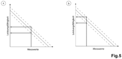
- the energy absorption capacity is determined either via the measured resistance using known or to be determined relationships (see Fig.5 ), for example, using statistics or previous measurements, or by determining the duration of the measurement, charging current and, advantageously, information about the voltage.
- the efficiency is calculated as the ratio of the amount of charge absorbed and released by the electrical energy storage device. Parasitic influences are taken into account when determining the resistance.
- the performance is determined on site or partly on site.
- an adapter can be connected between the charging device and the electrical energy storage device, which implements the method.
- the present method enables the objective comparison of different electrical energy storage devices. All necessary data is recorded outside the vehicle containing the energy storage device.
- the partial or complete local calculation of the performance enables the user to have quick access to the results without the need for a time-consuming determination of the load content or the time- and resource-consuming transfer of individual or all data to a cloud.
- the method uses a time-variable current increase or decrease to determine the performance, in particular the resistance, of the vehicle energy storage device, which means that the time-consuming (full) charging and/or (dis)charging, in particular complete (i.e. charging cycles >90%) or almost complete (i.e. charging cycles >50%), of the energy storage device can be dispensed with.
- This process makes it possible to use existing charging infrastructure. This saves resources that would otherwise be required to renew the charging infrastructure.
- the charging device is directly coupled to the vehicle energy storage and/or the intermediate circuit, so that data from the vehicle energy storage is accessed exclusively or at least primarily, the battery diagnostics for independent third parties who are not vehicle or battery manufacturers, thereby enabling an independent assessment of the state of charge of a vehicle energy storage system and opening up new business areas, both for research and for the private sector.
- the method according to the invention describes the determination of the performance of electrical vehicle energy storage systems.
- an electric vehicle energy storage device comprises at least one energy-storing element which is suitable for absorbing electrical energy and releasing it again when required.
- the energy storage device can also be referred to as a secondary battery, accumulator or battery.
- the process of absorbing electrical energy is referred to as charging. This takes place with a current and a voltage.
- the process of discharging the electrical energy from the energy-storing element is referred to as discharging.
- accumulators or secondary batteries which store electrical energy on an electrochemical basis.
- energy-storing elements also include batteries (primary batteries) which cannot be recharged.
- energy-storing element, accumulator and battery can be used synonymously.
- secondary batteries include lead accumulators, nickel-metal hydride accumulators, lithium-ion accumulators and nickel-cadmium accumulators.
- the accumulator cells can be connected in series and/or in parallel.
- Vehicles within the meaning of the invention include, in particular, automobiles, electric scooters, e-bikes, hoverboards, Segways, ships, boats and gliders. Also included are household appliances (e.g. vacuum cleaner robots) or model building devices (e.g. drones, model aircraft) that are operated with rechargeable batteries or energy storage devices. Since, according to the invention, detailed information from the vehicle can be dispensed with in order to determine the performance of the electric vehicle energy storage device, but only direct access to the energy storage device is required, the energy-storing element or the vehicle energy storage device can advantageously be installed in a vehicle during the method for determining its performance, or can be separate from it.
- household appliances e.g. vacuum cleaner robots
- model building devices e.g. drones, model aircraft
- the vehicle energy storage device is integrated into a vehicle during the implementation of the method for determining its performance. This saves advantageous unnecessary work steps for the laborious removal of the vehicle energy storage unit from the vehicle.
- energy storage includes stationary energy storage devices, i.e. devices in which accumulators are installed.
- the method according to the invention is intended in particular to allow the remaining performance of the energy storage device to be determined.
- the performance of an electrical energy storage device is understood to mean that the energy-storing element is able to fulfill a task intended for it.
- a task includes, for example, the provision of electrical energy in order to convert it either into kinetic energy (e.g. for operating an electric motor) and/or into thermal energy (e.g. for operating a heater).
- the electrical energy cannot be converted into another form of energy, for example if an electrical unit (e.g. sensors, computers) is to be operated.
- SoH State of Health
- the performance can also be an umbrella term for variables that have yet to be defined.
- the performance can, for example, be specified as a number.
- the performance can, for example, be specified according to a traffic light system (e.g. green, yellow, red).
- the performance can be specified as a rating (e.g. A, AA, AAA, B, BB, BBB). Regardless of how the performance is calculated, it should enable the vehicle owner to easily compare it with the performance of other vehicles.
- the performance of the energy storage device can be estimated by determining a first voltage of the energy storage device and/or the intermediate circuit, loading a specific - measured - amount of charge, which is not sufficient to completely fill the energy storage device, into the energy storage device and/or the intermediate circuit, and then determining a second voltage, and then concluding the performance from the comparison between the difference between the first and second voltages with an expected difference, whereby the expected difference is known from the specific, known amount of charge and previously known information (e.g. stored in lookup tables or a cloud) of the energy storage device or energy storage devices comparable to the energy storage device.
- Charging leads to a change in voltage. If the actual voltage change is compared with an expected one (e.g. from cloud statistics), the charge absorption capacity can be concluded.
- the method according to the invention comprises a charging device which can be detachably connected/installed in the vehicle or is permanently connected to the vehicle.
- the charging device is preferably directly and detachably connected to the energy storage device.
- a charging device is understood to be an element that delivers or receives an amount of electrical energy to the energy-storing element.
- a charging device is advantageously located outside the vehicle and is connected, at least during a charging or discharging process, to an energy source, for example an external supply network or another energy storage unit whose energy supply capacity allows a significant charge increase. What a significant charge increase is is defined in relation to the total capacity of the energy storage device and/or the usual consumption of a vehicle operated with the vehicle energy storage device.
- An exemplary charging device can easily charge the energy-storing element by at least 10%, or even more, for example 50%, up to 100%. For example, this happens in a few hours, or in less than an hour.
- a charging device also includes a device that allows additional functions, for example for recording/determining various parameters.
- the charging device and the energy storage device can be connected to one another via a data transmission cable, for example a CAN bus (controller area network), in addition to a charging cable and/or several power channels for supplying the energy storage device with electrical energy.
- a data transmission cable for example a CAN bus (controller area network)
- pure diagnostic devices are not charging devices, as the currents flowing here are generally negligible.
- the achievable current strengths are negligible, especially if a charge increase of 10% would take longer than 1 hour.
- the amount of energy emitted can, for example, be controlled by an information technology unit (e.g. computer, electronic circuit).
- an information technology unit e.g. computer, electronic circuit
- the charging device comprises at least two power channels.
- a power channel is understood to be an element that leads from an electrical pole of the charging device to an electrical pole of the energy-storing element, whereby the transported electrical energy is transported through the poles.
- the voltage between the power channels can be measured with a voltmeter.
- the current can be measured, for example, with an ammeter that is connected in series with the internal resistance of the energy-storing element. Alternatively, the current can be determined by measuring the voltage at a (known) resistance.
- a power channel comprises, for example, a charging cable or a plug.
- a power channel can also include a BUS as a communication interface (communication bus/data transfer bus).
- a BUS is understood to be a system that, in addition to, for example, current-carrying elements that charge a battery, includes conductor tracks that are used for information technology communication, i.e. the transmission of data in electronic form.
- a USB cable represents a BUS.
- data transfer standards include a Profibus, USB, OCPP (open charge point protocol).
- the current and/or voltage values can be measured at the charging device, which can be located inside or, preferably, outside the vehicle.
- a position inside the vehicle is understood to be any position of the charging device that results in the charging device's location following that of the vehicle.
- a position outside is understood to be when this is not the case.
- the charging device can comprise a direct current charging device (DC charging device) which emits or receives a direct current in order to charge the energy-storing element.
- DC charging device direct current charging device
- a circuit device can be provided which is designed to allow efficient galvanic isolation of a number N of specific energy storage devices from one another and at the same time a coupling to the charging device.
- the charging device can comprise an alternating current charging device (AC charging device) which delivers an alternating current in order to charge the energy-storing element.
- AC charging device alternating current charging device
- An AC-DC converter rectifier
- a single rectifier which is designed as an AC-DC converter
- several rectifiers or AC-DC converters can also be connected in parallel. This advantageously allows, for example, a number N of energy storage devices to be coupled to the charging device.
- a circuit device can be provided here which is designed to allow efficient galvanic isolation of a number N of energy storage devices both from the AC network and from one another and at the same time to allow coupling to the charging device.
- a control device for controlling the circuit device can be provided for a DC charging device and/or an AC charging device, which is designed to control a coupling of N specific energy storage devices with the charging device.
- the control device thus allows efficient switching of the circuit device for exchanging the number N energy storage devices with the charging device and thus error-free and uninterrupted charging of the vehicle energy storage devices and determination of the charging data of the vehicle energy storage device by the charging device.
- the charging device comprises an element which is configured to charge and/or discharge an energy storage device or an energy-storing element.
- a charging device for discharging an energy storage device is designed such that an energy storage device or connected energy-storing element connected to the charging device is to be discharged in order to advantageously reduce the electrical energy contained therein, so that the energy storage device or the energy-storing element can be removed from, for example, a vehicle and the risk of an explosion of the energy storage device or energy-storing element is prevented.
- Determining the performance using the method according to the invention involves directly or preferably indirectly measuring the resistance of the energy-storing element, i.e. here in particular taking into account and/or removing "parasitic" influences from other, measured components of the intermediate circuit or connecting elements.
- a resistance is understood to be an electrical resistance and/or impedance. This is a measure of the electrical voltage (volts) required to allow a certain electrical current (amperes) to flow through an electrical conductor (e.g. cable, accumulator).
- An electrical resistance is an ohmic effective resistance if its value is independent of the electrical voltage and the strength of the electrical current and other parameters (e.g. frequency).
- inductive elements e.g.
- the resistance changes depending on the frequency and in addition to the ohmic component of the resistance there is an apparent resistance.
- the total resistance is made up of the ohmic resistance and the apparent resistance and is also called impedance.
- the impedance can be calculated from the behavior of the current and the voltage and is used here as a synonym for resistance.
- the resistance of an energy-storing Unit such as a battery is related to its performance. With increasing age or charge/discharge cycles, the resistance of the battery increases and its performance decreases. Consequently, by determining the resistance at intervals of time, the performance can be determined or the performance can be determined approximately, particularly in a temporal comparison and/or particularly advantageous in comparison with other energy storage devices.
- the charging device is detachably connected to the vehicle.
- a detachable connection in the sense of the invention comprises a positive, non-positive or material connection or a combination of at least one of these, which is suitable for reversibly attaching the charging device to the vehicle.
- the performance of the energy-storing element is determined without influencing the current flow between the charging device and the energy storage device. Only the measured variables (i.e. at least one current and one voltage) that are determined between a control device of the energy storage device and the charging station, or directly from a user, are determined and used. Experts usually refer to this as a "negotiation", whereby the charging station is informed of the charging requirement, and possibly also the discharging requirement, in a suitable manner, and the charging station adjusts the current or power profile accordingly, possibly taking limit values into account.
- the resistance, and thus in further steps the performance, of the energy-storing element is determined indirectly via a calculation or approximation by adjusting the current flow delivered by the charging device in such a way that a variable current increase or current decrease (hereinafter referred to synonymously as current increase) is achieved per unit of time.
- a predetermined current increase per unit of time preferably comprises between 0.1 and 10.0 A per second, particularly preferably between 0.1 and 1.0 A per second and most particularly preferably between 0.3 and 0.8 A per second.
- the current increase can be predetermined by an information technology unit, whereby the information technology unit can influence the charging time and/or the charging voltage and/or the charging current by varying parameters.
- a charging current is applied to the energy storage device as a positively or negatively polarized charging or discharging current in pulses (i.e. variable current increase and current decrease, followed by a holding period, followed by a current decrease or current increase).
- the holding time of a charging pulse can, for example, be between a 1000th and a maximum of 600 seconds, preferably in the range between a 10th and a maximum of 60 seconds.
- the current intensity of the discharge or charge pulse can be varied in a targeted manner during the process for determining the performance of the energy storage device and can occur in smaller or larger amplitudes depending on the estimated charge state of the energy storage device, the estimated condition of the energy storage device or also depending on the estimated condition of the energy storage device and possibly also in shorter current times in order to increase the precision of the determination process, for example based on stored reference measurements.
- a resistance of the energy storage device and/or the intermediate circuit is therefore determined using a time-varying current.
- This can be variable during a charging or discharging pulse and is influenced by all components connected to the charging station (which are also counted as parasitic effects).
- the profile of the time-varying current can be variable pulse by pulse, whereby the pauses between the pulses can be the same length or different lengths.
- the pulses can be superimposed on an underlying profile.
- the design of the current profile is advantageously chosen so that parasitic influences can be isolated and, in particular, properties of the energy storage device come to the fore.
- the first current signal is made up of identical signals whose wave-shaped (in particular sinusoidal) or rectangular or other shape is transmitted at different times. This makes it possible to estimate the charge level of the energy storage device, the nature of the energy storage device or the state of the energy storage device.
- the comparison can be made, for example, by comparing the data obtained with reference values.
- control of the application of a pulsed charging or discharging current to the energy storage device can be carried out by a computer or by a processor of a control unit.
- a data processing system which comprises a processor adapted/configured to carry out the method or part of the steps of the proposed method.
- An information technology unit is an entity that is able to process and/or store electronic data and/or forward it and/or display it optically or visually.
- a charging device can represent an information technology unit.
- This also includes a peripheral device (adapter), provided that it is able to carry out at least one of the steps described.
- energy absorption capacity means the property of the energy-storing element to absorb or release a certain electrical energy and to store it.
- the energy absorption capacity is related to the charge absorption capacity, i.e. the ability of a storage device to absorb or release a certain amount of charge.
- the amount of charge that an accumulator or battery can store can be specified in ampere hours (Ah) and the maximum amount of charge that can be absorbed is also referred to as capacity (nominal capacity).
- An ampere hour is defined as the amount of charge that flows through a conductor within one hour when the electrical current is constant at 1 A.
- the energy absorption capacity can be determined by the ratio of measurement duration to average current level. For example, it is possible to determine in which period of time (measurement duration) which amount of current (current level) flowed into the accumulator until it reached its maximum charge.
- the voltage of the energy storage device changes in a characteristic manner, so that information about the voltage and in particular the change in voltage over the change in the charge quantity of the energy storage device, about the state and environmental information (e.g. temperature, parasitic effects) of the energy storage device, as well as about known or to be determined relationships between the above-mentioned variables on the maximum energy absorption capacity and the change over time and/or comparison with other energy storage devices is possible via the presence of open circuit voltage characteristics ("OCV") of the present Energy storage systems are advantageous, which can either be pre-determined and stored locally or in a cloud, or which result over time from the consideration of many measurements from which statistics can be created.
- OCV open circuit voltage characteristics
- the charge quantity/charge content of the battery can be determined by multiplying the average charging current by the charging time.
- efficiency is understood to be the ratio/quotient of the electrical power absorbed by the energy-storing element during charging and the electrical power emitted during discharging. If the quotient is formed in such a way that the output power is in the numerator, the efficiency for a loss-free accumulator is ideally 1 if the output power corresponds to the charging power absorbed. With increasing age and charging and discharging cycles, the internal resistance of the accumulator increases, whereby part of the absorbed electrical energy is lost as heat. As a result, the efficiency decreases.
- the ratio of the energy that can be extracted to the energy that must be used during charging is also referred to as the charging efficiency.
- parasitic influences are eliminated during the process for determining the performance of the energy storage system.
- Parasitic influences also: parasitic resistances or parasitic impedances or parasitic environmental conditions
- parasitic influences include physical influences that cannot be attributed to the energy-storing element but, for example, to those in the electrical supply path of a vehicle, e.g. the intermediate circuit or components thereof, as well as contact resistances, plugs, connecting elements, active and passive components, cables and lines.
- the internal resistance of the accumulator would not be considered a parasitic influence, but line resistances of the power channels, impedances in the circuit occurring outside the accumulator, plug resistances, or mutual inductions of spatially adjacent circuits would.
- the person skilled in the art knows which influences are covered by parasitic influences, which are covered by the so-called intermediate circuits.
- information about parasitic impedances in the electrical supply path of a vehicle can be determined by connecting the charger via two current-carrying power channels (connections) to one pole of an intermediate circuit to which the energy storage device is connected.
- Methods are known to those skilled in the art for obtaining information about impedances from known impedances of the charger and the voltage response of the measurement object to a suitable, dynamic and/or transient current excitation.
- a first voltage drop can first be determined at the two connections in a high-resistance state of the charger, then a second voltage drop can be determined at the two connections in a low-resistance state of the charger, each with a defined current flow, and then the parasitic resistance can be determined from the first voltage drop, the second voltage drop and the current strength.
- a first voltage drop can also first be determined at the two connections in a low-resistance state of the charger and then a second voltage drop can be determined in a high-resistance state of the charger.
- information about parasitic impedances can also be determined or estimated by examining the behavior of the voltage at/in the charging station and/or at the intermediate circuit and/or between the power channels with regard to the diffusion or intercalation-related impedance behavior, in particular relaxation behavior.
- typical energy storage devices in particular Li-ion batteries, are based on the diffusion or intercalation of charge carriers in an electrode. These processes are noticeable through a characteristic behavior of the voltage in response to current flow, which so few other known electrical components exhibit. The existence of this phenomenon was already described by Emil Warburg in 1899.
- information can be determined here from the temporal change in voltage ("relaxation") after (almost) complete cessation of current flows, and/or after an abrupt change in the current strength in or out of the energy storage device.
- the current flow in the low-resistance state can be generated in various ways.
- a test current can be fed into the charger.
- a consumer associated with the charger can be switched on to generate the current flow. In the latter case, all other electrical consumers in the vehicle can be in the idle state when the corresponding voltage drop is determined.
- the determination of performance using the method according to the invention can either be approximated on site (local pre-calculation) and/or calculated decentrally within a cloud-based information technology system.
- An on-site position is understood to be a position in the immediate vicinity of the vehicle, preferably within a radius of 50 meters, particularly preferably within a radius of 20 meters and most preferably within a radius of 5 meters.
- an on-site position is understood to be a position that is in the same building as the vehicle.
- an approximation on site results in a quick determination of the performance of the accumulator even if there is no internet connection.
- a more precise calculation can be carried out in a cloud-based information technology system (cloud), which requires an internet connection.
- the communication path between the device for determining the performance of the information technology unit and the cloud can include a cable connection (e.g. Ethernet cable connection) and a radio connection (e.g. LTE, 4G, 5G) or a connection via WLAN.
- access by one or more information technology units to the cloud enables the inclusion of data stored there on one or more battery types that are installed in one or more vehicles.
- the stored data can also be stored in another information technology unit (e.g. smartphone, notebook, hard drive, USB stick).
- a decentralized cloud-based information technology system comprises one which receives, processes, stores, transmits or sends measured values (e.g. voltage, current, temperature, humidity) by means of at least one information technology unit, or a combination of at least one of these.
- measured values comprise physical quantities that can be derived either directly or indirectly from the SI units. Measured values include, for example, temperature, time, distance (e.g. mileage in km), current, voltage, humidity, acceleration, speed.
- physical quantities can also be estimated, whereby certain physical quantities are used to estimate another physical quantity. For example, with the help of a thermometer, e.g.
- thermometer particularly advantageously an infrared thermometer, which is arranged underneath a vehicle in the charging station, at least one, advantageously several spatially distributed, temperatures of the housing of the energy storage device can be determined.
- knowledge about the temperature distribution of the energy storage device can be estimated without having to access systems inside the vehicle, which is not possible for a third party.
- conclusions can advantageously be drawn about the thermal, electrochemical, chemical and/or thermodynamic equilibrium of the energy storage device.
- the determination of measured values can be carried out directly or indirectly on at least one vehicle and/or battery, and/or charging device, and/or other element (e.g. adapter).
- the determination of measured values takes place at intervals of time.
- a measurement period includes, for example, the usage time of the battery.
- a period is also understood to be the time difference between an older and a more recent measurement.
- a measurement is carried out at a point in time, with the measured values obtained being stored in order to make them retrievable for a later measurement, for example.
- the recording of different measured values enables a differentiated determination of the performance of the energy-storing element and a forecast of the expected development of the performance.
- the ambient temperature and/or surface temperature of the vehicle and/or energy-storing element can be determined in order to allow conclusions to be drawn about the temperature or the equilibrium state of the energy-storing element.
- the core temperature of the energy-storing element can also be determined.
- the surface temperature of the vehicle floor can also be determined.
- an information technology unit can adjust the strength of the charging current and/or the charging voltage depending on one or more than one measured value.
- the standstill time is understood to be the period in which the vehicle is not moved, whereas the driving time describes the period in which the vehicle is moved, while the operating time describes the period in which energy is taken from or absorbed by the energy storage device.
- This must be distinguished from the running time, which describes the period in which the accumulator is discharged without the vehicle being moved.
- the determination of the downtime can advantageously be used to estimate how far the energy storage device is from its thermal, chemical, electrochemical and/or thermodynamic equilibrium, which has an influence on the resistance measurement.
- the measured values are taken at periodic intervals, whereby an information technology unit can determine the intervals.
- the cloud contains stored data (lookup tables) on the specifications of the different accumulators.
- a lookup table contains data on the charging processes, as well as reference data from the accumulator manufacturers. The data can be obtained from the manufacturers who publish the corresponding key figures (e.g. nominal voltage, capacity).
- the key figures for more than one vehicle and/or more than one energy-storing unit are stored in the cloud.
- the data stored in the cloud are used to create statistics that form the basis for assessing performance.
- the statistics initially contain data stored on the energy-storing element, for example data from the manufacturer, with the statistics being expanded to include collected data in order to better assess performance.
- At least one information technology unit compares the data stored in the cloud with the measured values determined.
- the data from the cloud is sent to one or more mobile telecommunications devices (e.g. smartphone, tablet, notebook), which enables a graphical display of the data.
- the measured values determined are transmitted to the cloud and compared there with the measured values of other accumulators.
- the information on each individual accumulator that is charged via a charging device that is directly or indirectly connected to the cloud is stored in the cloud.
- an algorithm and/or preferably an artificial intelligence (AI) that has access to the cloud can decide which accumulator is charged with which charging voltages and/or charging currents and/or charging times.
- the AI can therefore determine optimal charging curves.
- the advantage of this is that the AI can use a model to determine the parameters that result in optimal performance of the accumulator based on the measured values that develop differently over time for each accumulator.
- the AI must ensure that it only varies the parameters within a limited range so that no customer has to accept an intolerable negative impairment of performance caused by the AI.
- the advantage of this is that the energy-storing element has improved performance.
- the measured values of the accumulators stored in the cloud and/or processed by a Kl are determined and processed.
- the measured values preferably come from more than one, particularly preferably more than a thousand and most preferably more than a million vehicles and/or energy-storing elements.
- the measured values are collected by a measuring device that is installed with the vehicle and/or the energy-storing element and/or an adapter and/or the charging device and serves to determine physical quantities (e.g. temperature, voltage, current, acceleration, speed).
- a measuring device can be at least one heat-dependent resistor (e.g. NTC resistor, PTC resistor) or a contactless temperature measuring device (e.g. an infrared thermometer) that is located on and/or next to and/or inside the energy-storing element and transmits information to the measuring device via an electrical circuit.
- a measuring device is not to be understood as a single element in the sense of the invention. Instead, the measuring device comprises all elements that record a physical quantity, whereby the measured values can be recorded simultaneously and/or not simultaneously.
- a mat can be located underneath the vehicle in which temperature sensors, e.g. contactless ones, are arranged in order to allow conclusions to be drawn about at least one representative temperature, e.g. the average interior temperature or the temperature distribution of the energy-storing element, via the measurement and with the help of statistics.
- temperature sensors e.g. contactless ones
- the method according to the invention is implemented with an adapter, which represents a design of an information technology unit, in which one or more measuring devices are integrated.
- the adapter advantageously has control over the current intensity delivered by the charging unit. This is particularly advantageous if the charging unit itself cannot establish contact with a cloud, but the adapter can. This can then access the stored data and regulates the charging time and/or the charging voltage and/or the charging current depending on this.
- One embodiment of the method according to the invention for determining the performance of electric vehicle energy storage devices comprises determining the state of charge (SoC) of the energy-storing element (e.g. accumulator) to determine the performance.
- SoC state of charge
- the SoC value indicates the amount of charge still available in an accumulator in relation to the nominal value.
- the state of charge is given as a percentage of the fully charged state. For example, an SoC of 30% means that the accumulator still has a residual charge of 30% based on the original full charge of 100%. With knowledge or an estimate of the SoC, the energy storage capacity can be advantageously determined.
- the information about the charging state can be transmitted by an additional communication interface between the vehicle and the charging station, whereby the additional communication interface can comprise an adapter.
- a communication interface also comprises the charging cable or the vehicle driver, who makes a manual input, i.e. a manual transmission of data to, for example, a charging device.
- the adapter establishes a connection to the cloud in order to exchange data with it or to store data in it.
- the adapter establishes a connection to one or more mobile telecommunications devices (e.g. smartphone, tablet, notebook) and/or a technical unit that processes information technology signals for data exchange.
- An additional communication interface advantageously means that the charging device does not have to be coordinated with the battery management system (BMS). Instead, the additional communication interface ensures that the BMS correctly exchanges data with the charging device and/or at least one other information technology unit.
- the measured values determined for the energy-storing unit include, for example, physical variables such as voltage, current (in particular current peaks), temperature, temperature fluctuations, humidity and the age of the battery. Measured values can also include the vehicle movement, in particular the acceleration. A more precise calculation of the performance of the energy-storing element can advantageously be achieved with the aid of a combination of individual measured values.
- the age of the energy-storing element is understood to be the period from its first use to the current time of use.
- the age of a battery advantageously allows a more differentiated determination of the performance of the energy-storing element.
- parts of the measured values can be read out by a diagnostic interface, a head-up display or a dashboard or a combination thereof.
- the reading can be carried out by an information technology unit.
- the reading can be carried out in such a way that the vehicle driver manually transmits the measured values to an information technology unit.
- the vehicle and/or the energy-storing element can be clearly identified using an identification method.
- the person skilled in the art is aware of various possibilities for providing objects, in particular electronic systems (e.g. the vehicle, the accumulator) and information technology systems, with an identifier that can be determined and processed by an information technology unit (e.g. data stored on an RFID chip).
- the identifier is transmitted to the adapter and/or the charging device and/or the cloud and/or the mobile communication device.
- the vehicle, and/or the energy-storing element, and/or the adapter, and/or the charging device and/or the cloud and/or the mobile communication device comprise an identifier.
- an identifier comprises a numerical value such as 283163849.
- the identifier can be visibly applied to the unit that it identifies and/or stored in information technology.
- An identifier also includes a vehicle identification number, a MAC address, or the vehicle’s license plate number.
- the identification of the vehicle and/or the energy-storing element is carried out by a user input on a display.
- the display transmits the entered information to an information technology unit for processing.
- the charging device comprises a display.
- the display can be part of the vehicle, the mobile communication device, or the adapter.
- identification can be carried out via a charging card that is inserted into the charging device.
- the identification of the vehicle and/or the energy-storing element and/or the driver/user is carried out via a camera.
- the identification can be designed in such a way that the vehicle license plate or the driver's facial print is stored in an information technology system (e.g. the cloud), with the data on the vehicle and/or the energy-storing unit being stored at the same time.
- the vehicle owner does not have to make any manual input.
- Alternative embodiments use, for example, an iris scan and/or a fingerprint of the driver.
- the identification of the vehicle and/or the energy-storing element is carried out using Plug and Charge or Autocharge or OCCP.
- Plug and Charge or Autocharge or OCCP With charging devices that work with these methods, charging processes are started or ended simply by connecting or disconnecting the charging cable. This eliminates the need to use a charging card for identification. Both are standardized charging methods that offer an additional communication interface and at least one identification option.
- the energy absorption capacity is determined to determine the performance, i.e. the time period in which the energy-storing element reaches the maximum charge content. This is relevant for the determination because as a battery ages, its ability to store a defined amount of charge in a given time deteriorates. Suppose a new and an older battery of the same model were charged with the same charging voltage, with the current adjusting according to the resistance. While the new battery reaches a charge content of 100 kWh within 10 hours, for example, an old battery reaches a charge content of 90 kWh within 13 hours. Its performance is therefore worse. Therefore, recording this time period can be used to determine the performance.
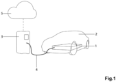
- the method according to the invention comprises an electrically operated vehicle EV ( electric vehicle ) 2 with an electrical energy storage device 1, a charging device 3, which is detachably connected to the electrical energy storage device 1 via a charging cable 4.
- a device for determining the performance is integrated in the charging device 3 and communicates via an additional communication bus, which is combined with the charging cable 4 . with the electrical energy storage device 1 and via a second communication path with a cloud server 5.
- the energy storage device is formed from a lithium-ion battery, wherein the performance of the electrical energy storage device 1 is related to the resistance and the energy absorption capacity of the energy storage device 1 and wherein the performance is abbreviated to SoH (State of Health) and wherein the electrical energy storage device 1 consists of battery cells connected in parallel and in series.
- SoH State of Health
- the data transmission bus between the device for determining performance and the electrical energy storage device 1 is designed as a serial interface and uses the CAN bus transmission standard.
- the device for determining performance thereby accesses sensor values of the vehicle and the electrical energy storage device, such as charging current, charging voltage, SOC ( state of charge ), and the cell temperature inside the electrical energy storage device 1 , provided that these have been approved by the manufacturer.
- sensor values of the vehicle and the electrical energy storage device such as charging current, charging voltage, SOC ( state of charge ), and the cell temperature inside the electrical energy storage device 1 , provided that these have been approved by the manufacturer.
- historical data of the electrical energy storage device 1 such as charging cycles and mileage of the vehicle, downtime of the vehicle, temperature profile of the vehicle floor and the vehicle environment, are transmitted to the device for determining performance.
- the data during the charging process which include current, voltage, SOC and temperature inside the electrical energy storage device 1 , are recorded in real time by the device for determining the performance.
- a unique identification procedure is used to identify and assign electrical energy storage units 1 and vehicles 2.
- the identification features are transmitted via the additional communication interface for the identifier.
- vehicles and electrical energy storage units are identified by user input or by image recognition using a camera or by plug and charge or by autocharge.
- the communication path between the performance measurement device and the cloud server is established through an Ethernet cable connection.
- the charging data and historical data of various electrically operated vehicles 2 and electrical energy storage devices are stored on the cloud server in a lookup table. These data are retrieved by the device for determining the performance and are supplemented after each charging process with the charging data and historical data measured during the charging process.
- parasitic influences of the charging device and the electrical energy storage device are taken into account. These parasitic influences include cable resistance and mutual induction, energy consumption by secondary consumers and contact resistance.
- the charging current is set in pulsed mode.
- the pulse width or the amplitude of the pulse is set variably ( Fig. 3a ).
- the current is also adjusted with a variable pulse width or amplitude ( Fig. 3b ).
- the charging and discharging voltage can also be set to vary over time with variable pulse width or amplitude ( Fig. 3c and 3d ) .
- a transient (time-varying) charging current is set by the charging device, as in Fig.4
- the charging current increases in Fig. 4a with a predetermined rise and falls with small, regular descents until it reaches a prescribed current strength.
- the impedance and hence the resistance of the electrical energy storage device 1 are determined from the response of the voltage.
- the corresponding parasitic resistances are then taken into account.
- the corresponding charge contents are given for the specific resistances, i.e. measured values, from which the performance is concluded, as in Fig. 5a
- the historical reference values result in a spread, which is shown by the dashed lines. The more reference values there are, the more accurate the result will be.
- Fig. 5b The measured values of another energy storage device are compared with the reference values in order to determine its performance.
- the average charging current is multiplied by the charging time to determine the charge quantity of the electrical energy storage device.
- the corresponding parasitic influences are then taken into account.
- the efficiency of an electrical energy storage device is determined by comparing the discharge quantity to the charge quantity.
- Fig.6 In a further embodiment, in addition to the first embodiment, further measured values are taken into account for determining the performance of electrical energy storage 1. Another measured value is the SOC of electrical energy storage 1. The SOC is transmitted via a communication interface from the BMS ( battery management system) to the device for determining the performance.
- BMS battery management system
- Another way to determine the SOC is to measure the charging voltage and charging current. These measured values are compared with reference values of a new electrical reference energy storage device from a lookup table on a cloud server.
- the lookup table on the cloud server contains historical charging data and identification features of vehicles and electrical energy storage devices.
- the maximum current flow of a new electrical reference energy storage device must be 0.25 1/h of the maximum charge content.
- Fig.7 A further embodiment takes into account further measured values for determining the performance of electrical energy storage devices, wherein one measured value is the temperature of the electrical energy storage device and wherein this temperature is provided either by the SOC ( Fig.8 S5 ), or in alternative embodiments based on weather values, such as the temperature, temperature fluctuations and humidity of the vehicle environment ( Fig.8 S1 ), the surface temperature of the energy storage device ( Fig.8 S2 ), of the vehicle ( Fig.8 S3 ) or the vehicle floor ( Fig.8 S4 ). These parameters are recorded over a period of time and the temperature of the electrical energy storage device is determined from this, whereby this period includes the driving time as well as the idle time of the vehicle. These measured values are transmitted via a communication interface to the device for assessing the performance.
- SOC Fig.8 S5
- weather values such as the temperature, temperature fluctuations and humidity of the vehicle environment ( Fig.8 S1 ), the surface temperature of the energy storage device ( Fig.8 S2 ), of the vehicle ( Fig
- the age of the electrical energy storage device is used as a further parameter for determining the performance.
- the mileage of the vehicle with this electrical energy storage device is taken into account.
- the license plate is read using a camera ( Fig.8 S6 ).
- the camera ( Fig.8 S6 ) is additionally or exclusively capable of generating thermal images.
- the current temperature of the energy storage device is determined from the thermal image.
- the temperature profile when the vehicle is stationary in front of the charging device is determined.
- an adapter 6 can alternatively be attached to supplement the charging device 3. This contains all functions for assessing the performance of electrical energy storage devices 1 and is connected to the charging device via a charging cable 4. In another embodiment, the adapter 6 communicates directly with the cloud server 5 via a wireless Internet connection ( Fig. 9b ).
- An intermediate circuit (7) of an electrically powered vehicle is shown in Fig.10 shown.
- An intermediate circuit (7) is defined here as the set of galvanically coupled components (1, 8, 9), for example auxiliary consumers, power electronics, motors, heating/cooling devices, with their own respective electrical parasitic properties, one of these components corresponding to the vehicle energy storage device (1), as well as the parasitic impedances (9) in between, such as contact and cable/line resistances, parasitic capacitances and inductances and stray capacitances and stray inductances, and the connections of the power channels (10) for the electrical power consumption from the charging device.
- the voltage that a measuring device in the charging device measures between the two power channels (10) corresponds to the voltage between the poles of the intermediate circuit (11), taking into account current or parasitic effects.
- the current that can flow from the charging device towards the intermediate circuit will be distributed between the various components according to the parasitic impedance properties of the components. Part of the current will flow into the vehicle energy storage device (1).
- the effect of the parasitic components can be determined or estimated and thus conclusions can be drawn about the electrical properties of the vehicle energy storage device.
Landscapes
- Engineering & Computer Science (AREA)
- Power Engineering (AREA)
- Transportation (AREA)
- Mechanical Engineering (AREA)
- General Chemical & Material Sciences (AREA)
- Manufacturing & Machinery (AREA)
- Chemical & Material Sciences (AREA)
- Chemical Kinetics & Catalysis (AREA)
- Electrochemistry (AREA)
- Sustainable Development (AREA)
- Sustainable Energy (AREA)
- Life Sciences & Earth Sciences (AREA)
- Microelectronics & Electronic Packaging (AREA)
- Physics & Mathematics (AREA)
- General Physics & Mathematics (AREA)
- Secondary Cells (AREA)
- Charge And Discharge Circuits For Batteries Or The Like (AREA)
Applications Claiming Priority (3)
| Application Number | Priority Date | Filing Date | Title |
|---|---|---|---|
| DE102021118781.8A DE102021118781A1 (de) | 2021-07-20 | 2021-07-20 | Verfahren zur Bestimmung der Leistungsfähigkeit von elektrischen Fahrzeug-Energiespeichern |
| PCT/EP2022/070392 WO2023001906A1 (fr) | 2021-07-20 | 2022-07-20 | Procédé de détermination de la capacité d'accumulateurs d'énergie électrique de véhicule |
| EP22744221.7A EP4217754B1 (fr) | 2021-07-20 | 2022-07-20 | Procédé de détermination de la capacité d'accumulateurs d'énergie électrique de véhicule |
Related Parent Applications (1)
| Application Number | Title | Priority Date | Filing Date |
|---|---|---|---|
| EP22744221.7A Division EP4217754B1 (fr) | 2021-07-20 | 2022-07-20 | Procédé de détermination de la capacité d'accumulateurs d'énergie électrique de véhicule |
Publications (2)
| Publication Number | Publication Date |
|---|---|
| EP4350938A2 true EP4350938A2 (fr) | 2024-04-10 |
| EP4350938A3 EP4350938A3 (fr) | 2024-07-17 |
Family
ID=82611080
Family Applications (2)
| Application Number | Title | Priority Date | Filing Date |
|---|---|---|---|
| EP22744221.7A Active EP4217754B1 (fr) | 2021-07-20 | 2022-07-20 | Procédé de détermination de la capacité d'accumulateurs d'énergie électrique de véhicule |
| EP24155407.0A Pending EP4350938A3 (fr) | 2021-07-20 | 2022-07-20 | Méthode de détermination de la performance des accumulateurs d'énergie électrique |
Family Applications Before (1)
| Application Number | Title | Priority Date | Filing Date |
|---|---|---|---|
| EP22744221.7A Active EP4217754B1 (fr) | 2021-07-20 | 2022-07-20 | Procédé de détermination de la capacité d'accumulateurs d'énergie électrique de véhicule |
Country Status (6)
| Country | Link |
|---|---|
| US (1) | US20250091478A1 (fr) |
| EP (2) | EP4217754B1 (fr) |
| CN (1) | CN117751297A (fr) |
| DE (1) | DE102021118781A1 (fr) |
| ES (1) | ES2985231T3 (fr) |
| WO (1) | WO2023001906A1 (fr) |
Families Citing this family (6)
| Publication number | Priority date | Publication date | Assignee | Title |
|---|---|---|---|---|
| KR20230072818A (ko) * | 2021-11-18 | 2023-05-25 | 현대자동차주식회사 | 배터리 컨디셔닝 시스템 및 방법 |
| DE102022208191A1 (de) * | 2022-08-05 | 2024-02-08 | Robert Bosch Gesellschaft mit beschränkter Haftung | Verfahren zum Überwachen eines Energiespeichers in einem Kraftfahrzeug |
| DE102023122517A1 (de) * | 2023-08-23 | 2025-02-27 | Bayerische Motoren Werke Aktiengesellschaft | Bestimmen eines Gesundheitszustands eines Hochvoltspeichers eines Elektrofahrzeugs |
| CN117895662B (zh) * | 2024-03-14 | 2024-06-11 | 江苏智融能源科技有限公司 | 一种基于边缘计算的设备需求监测系统及方法 |
| DE102024114581B3 (de) * | 2024-05-24 | 2025-11-27 | Bayerische Motoren Werke Aktiengesellschaft | Verfahren zum Einrichten einer Fahrzeugbatterie sowie Batteriemanagementsystem für eine Fahrzeugbatterie eines Kraftfahrzeugs |
| DE102024126316A1 (de) | 2024-09-12 | 2026-03-12 | Audi Aktiengesellschaft | Batteriebetriebenes Fahrzeug sowie Verfahren zum Betreiben eines solchen batteriebetriebenen Fahrzeugs |
Citations (5)
| Publication number | Priority date | Publication date | Assignee | Title |
|---|---|---|---|---|
| EP2306214A2 (fr) | 2009-09-30 | 2011-04-06 | Tesla Motors, Inc. | Détermination d'impédance CC d'une batterie |
| WO2011135813A1 (fr) | 2010-04-26 | 2011-11-03 | 日本電気株式会社 | Système permettant de gérer l'état d'un accumulateur, chargeur de batterie, procédé permettant de gérer l'état d'un accumulateur et procédé de mesure de caractéristiques électriques |
| EP2065718B1 (fr) | 2006-08-30 | 2012-04-18 | Toyota Jidosha Kabushiki Kaisha | Procédé et système d'évaluation de la dégradation d'un accumulateur dans un véhicule |
| DE102017125274B3 (de) | 2017-10-27 | 2019-03-21 | Borgward Trademark Holdings Gmbh | Verfahren zur Erfassung des Gesundheitszustands einer Batterie, zugehörige Einrichtung, zugehöriges System und Speichermedium |
| WO2020045059A1 (fr) | 2018-08-28 | 2020-03-05 | 本田技研工業株式会社 | Dispositif de diagnostic, procédé de diagnostic, système de diagnostic, et programme |
Family Cites Families (7)
| Publication number | Priority date | Publication date | Assignee | Title |
|---|---|---|---|---|
| US8063609B2 (en) | 2008-07-24 | 2011-11-22 | General Electric Company | Method and system for extending life of a vehicle energy storage device |
| US9180783B1 (en) | 2011-04-22 | 2015-11-10 | Penilla Angel A | Methods and systems for electric vehicle (EV) charge location color-coded charge state indicators, cloud applications and user notifications |
| CN103826906B (zh) | 2011-08-16 | 2016-10-12 | 高级管理有限公司 | 与动力补充站相邻的电动交通工具的标识 |
| CA3006517A1 (fr) | 2015-12-22 | 2017-06-29 | Vito Nv | Dispositif de mesure de caracteristiques de batteries a haute tension |
| US10209314B2 (en) | 2016-11-21 | 2019-02-19 | Battelle Energy Alliance, Llc | Systems and methods for estimation and prediction of battery health and performance |
| US11079441B2 (en) | 2018-06-05 | 2021-08-03 | Honda Motor Co., Ltd. | Internal resistance estimating method, and secondary battery charging device |
| SE543436C2 (en) * | 2019-06-03 | 2021-02-16 | Alelion Energy Systems Ab | Method for estimating state of health of a battery |
-
2021
- 2021-07-20 DE DE102021118781.8A patent/DE102021118781A1/de not_active Withdrawn
-
2022
- 2022-07-20 WO PCT/EP2022/070392 patent/WO2023001906A1/fr not_active Ceased
- 2022-07-20 EP EP22744221.7A patent/EP4217754B1/fr active Active
- 2022-07-20 US US18/290,712 patent/US20250091478A1/en active Pending
- 2022-07-20 ES ES22744221T patent/ES2985231T3/es active Active
- 2022-07-20 EP EP24155407.0A patent/EP4350938A3/fr active Pending
- 2022-07-20 CN CN202280051596.0A patent/CN117751297A/zh active Pending
Patent Citations (5)
| Publication number | Priority date | Publication date | Assignee | Title |
|---|---|---|---|---|
| EP2065718B1 (fr) | 2006-08-30 | 2012-04-18 | Toyota Jidosha Kabushiki Kaisha | Procédé et système d'évaluation de la dégradation d'un accumulateur dans un véhicule |
| EP2306214A2 (fr) | 2009-09-30 | 2011-04-06 | Tesla Motors, Inc. | Détermination d'impédance CC d'une batterie |
| WO2011135813A1 (fr) | 2010-04-26 | 2011-11-03 | 日本電気株式会社 | Système permettant de gérer l'état d'un accumulateur, chargeur de batterie, procédé permettant de gérer l'état d'un accumulateur et procédé de mesure de caractéristiques électriques |
| DE102017125274B3 (de) | 2017-10-27 | 2019-03-21 | Borgward Trademark Holdings Gmbh | Verfahren zur Erfassung des Gesundheitszustands einer Batterie, zugehörige Einrichtung, zugehöriges System und Speichermedium |
| WO2020045059A1 (fr) | 2018-08-28 | 2020-03-05 | 本田技研工業株式会社 | Dispositif de diagnostic, procédé de diagnostic, système de diagnostic, et programme |
Also Published As
| Publication number | Publication date |
|---|---|
| CN117751297A (zh) | 2024-03-22 |
| EP4350938A3 (fr) | 2024-07-17 |
| US20250091478A1 (en) | 2025-03-20 |
| ES2985231T3 (es) | 2024-11-04 |
| EP4217754A1 (fr) | 2023-08-02 |
| EP4217754B1 (fr) | 2024-02-07 |
| DE102021118781A1 (de) | 2023-01-26 |
| WO2023001906A1 (fr) | 2023-01-26 |
| EP4217754C0 (fr) | 2024-02-07 |
Similar Documents
| Publication | Publication Date | Title |
|---|---|---|
| EP4217754B1 (fr) | Procédé de détermination de la capacité d'accumulateurs d'énergie électrique de véhicule | |
| DE102010024241B4 (de) | Verfahren zur Verwendung mit einem Fahrzeugbatteriestapel, der eine Vielzahl von Batteriezellen aufweist | |
| DE102014102667B4 (de) | Verfahren und system zum schätzen der spannung eines batterieelements | |
| DE102014102668B4 (de) | Verfahren und system zum bestimmen der spannung eines batterieelements | |
| DE102010050803B4 (de) | Verfahren zum Abschätzen der Batterieverschlechterung in einem Fahrzeugbatteriesatz | |
| DE102015107930B4 (de) | Schätzung und Ausgleich von Batteriemessungen | |
| DE102009038663B4 (de) | Kraftwagen mit einer Mehrzahl von Batterien und Verfahren zur Batteriediagnose | |
| DE102015208264B4 (de) | Schätzung des ladezustands von batteriezellen | |
| DE102015116102B4 (de) | Schaltung und Verfahren zur Detektion der Batteriezellenentladung | |
| DE102016119166B4 (de) | Adaptive identifikation des verdrahtungswiderstands in einer traktionsbatterie | |
| EP3323667B1 (fr) | Système de stockage d'énergie de traction à limitation de fonctionnement | |
| DE102013220688B4 (de) | Verfahren und Vorrichtung zur Bestimmung eines ladungszustandsabhängigen Leerlaufspannungsverlaufs einer Fahrzeugbatterie | |
| WO2021083587A1 (fr) | Procédé de charge rapide | |
| DE102015110940A1 (de) | Fast charge algorithms for lithium-ion batteries | |
| DE102015206604A1 (de) | System zur abschätzung der batterietemperatur | |
| DE102015203461A1 (de) | System und verfahren zur beurteilung des gesundheitszustands anhand von batteriemodellparametern | |
| DE102009049589A1 (de) | Verfahren zur Bestimmung und/oder Vorhersage der maximalen Leistungsfähigkeit einer Batterie | |
| DE102020121180A1 (de) | Schätzsystem und Schätzverfahren | |
| DE102013220015A1 (de) | Verfahren und System zum Schätzen der Batteriekapazität in einem Fahrzeug | |
| DE112009001553T5 (de) | Verfahren zur Batteriekapazitätsschätzung | |
| DE102011054339A1 (de) | Adaptive Iangsam veränderliche Stromerkennung | |
| DE102009036083A1 (de) | Verfahren zum Steuern einer Batterie und Vorrichtung zur Durchführung des Verfahrens | |
| DE102021125478B4 (de) | Bestimmung eines alterungswerts für batterien mit strom-spannungs-zeitreihen in zeitdomäne und belastungsdomäne | |
| DE102010062187A1 (de) | Verfahren zur Ermittlung der Leerlaufspannung einer Batterie, Batterie mit einem Modul zur Ermittlung der Leerlaufspannung sowie ein Kraftfahrzeug mit einer entsprechenden Batterie | |
| DE102015109282A1 (de) | System und Verfahren zum Batteriemanagement |
Legal Events
| Date | Code | Title | Description |
|---|---|---|---|
| PUAI | Public reference made under article 153(3) epc to a published international application that has entered the european phase |
Free format text: ORIGINAL CODE: 0009012 |
|
| STAA | Information on the status of an ep patent application or granted ep patent |
Free format text: STATUS: REQUEST FOR EXAMINATION WAS MADE |
|
| 17P | Request for examination filed |
Effective date: 20240226 |
|
| AC | Divisional application: reference to earlier application |
Ref document number: 4217754 Country of ref document: EP Kind code of ref document: P |
|
| AK | Designated contracting states |
Kind code of ref document: A2 Designated state(s): AL AT BE BG CH CY CZ DE DK EE ES FI FR GB GR HR HU IE IS IT LI LT LU LV MC MK MT NL NO PL PT RO RS SE SI SK SM TR |
|
| REG | Reference to a national code |
Ref country code: DE Ref legal event code: R079 Free format text: PREVIOUS MAIN CLASS: H02J0007000000 Ipc: G01R0031392000 |
|
| PUAL | Search report despatched |
Free format text: ORIGINAL CODE: 0009013 |
|
| STAA | Information on the status of an ep patent application or granted ep patent |
Free format text: STATUS: EXAMINATION IS IN PROGRESS |
|
| AK | Designated contracting states |
Kind code of ref document: A3 Designated state(s): AL AT BE BG CH CY CZ DE DK EE ES FI FR GB GR HR HU IE IS IT LI LT LU LV MC MK MT NL NO PL PT RO RS SE SI SK SM TR |
|
| RIC1 | Information provided on ipc code assigned before grant |
Ipc: H01M 10/42 20060101ALI20240610BHEP Ipc: H01M 10/44 20060101ALI20240610BHEP Ipc: H02J 7/00 20060101ALI20240610BHEP Ipc: H01M 10/48 20060101ALI20240610BHEP Ipc: G01R 31/392 20190101AFI20240610BHEP |
|
| 17Q | First examination report despatched |
Effective date: 20240626 |
|
| GRAP | Despatch of communication of intention to grant a patent |
Free format text: ORIGINAL CODE: EPIDOSNIGR1 |
|
| STAA | Information on the status of an ep patent application or granted ep patent |
Free format text: STATUS: GRANT OF PATENT IS INTENDED |
|
| RIC1 | Information provided on ipc code assigned before grant |
Ipc: G01R 31/392 20190101AFI20260303BHEP Ipc: H01M 10/48 20060101ALI20260303BHEP Ipc: H02J 7/00 20060101ALI20260303BHEP Ipc: H01M 10/44 20060101ALI20260303BHEP Ipc: H01M 10/42 20060101ALI20260303BHEP |
|
| INTG | Intention to grant announced |
Effective date: 20260313 |