EP4351077A1 - Procédé et appareil de transmission de capacité d'équipement utilisateur, et support de stockage - Google Patents
Procédé et appareil de transmission de capacité d'équipement utilisateur, et support de stockage Download PDFInfo
- Publication number
- EP4351077A1 EP4351077A1 EP21942290.4A EP21942290A EP4351077A1 EP 4351077 A1 EP4351077 A1 EP 4351077A1 EP 21942290 A EP21942290 A EP 21942290A EP 4351077 A1 EP4351077 A1 EP 4351077A1
- Authority
- EP
- European Patent Office
- Prior art keywords
- frequency band
- user equipment
- downlink
- uplink
- working frequency
- Prior art date
- Legal status (The legal status is an assumption and is not a legal conclusion. Google has not performed a legal analysis and makes no representation as to the accuracy of the status listed.)
- Pending
Links
- 238000000034 method Methods 0.000 title claims abstract description 103
- 230000004044 response Effects 0.000 claims abstract description 18
- 238000004891 communication Methods 0.000 claims description 74
- 230000005540 biological transmission Effects 0.000 claims description 14
- 230000002776 aggregation Effects 0.000 claims description 11
- 238000004220 aggregation Methods 0.000 claims description 11
- 238000004590 computer program Methods 0.000 claims description 10
- 238000001228 spectrum Methods 0.000 abstract description 8
- 238000012545 processing Methods 0.000 description 28
- 230000006870 function Effects 0.000 description 15
- 238000010586 diagram Methods 0.000 description 11
- 238000013461 design Methods 0.000 description 8
- 238000005516 engineering process Methods 0.000 description 8
- 238000007726 management method Methods 0.000 description 4
- 230000003287 optical effect Effects 0.000 description 4
- 230000005236 sound signal Effects 0.000 description 4
- 230000011664 signaling Effects 0.000 description 3
- 230000009471 action Effects 0.000 description 2
- 230000008859 change Effects 0.000 description 2
- 230000003993 interaction Effects 0.000 description 2
- 238000010295 mobile communication Methods 0.000 description 2
- 230000008569 process Effects 0.000 description 2
- 230000001133 acceleration Effects 0.000 description 1
- 238000003491 array Methods 0.000 description 1
- 230000001413 cellular effect Effects 0.000 description 1
- 238000006243 chemical reaction Methods 0.000 description 1
- 239000003795 chemical substances by application Substances 0.000 description 1
- 238000013500 data storage Methods 0.000 description 1
- 238000003384 imaging method Methods 0.000 description 1
- 230000000977 initiatory effect Effects 0.000 description 1
- 239000004973 liquid crystal related substance Substances 0.000 description 1
- 230000007774 longterm Effects 0.000 description 1
- 238000005259 measurement Methods 0.000 description 1
- 230000002093 peripheral effect Effects 0.000 description 1
- 230000002040 relaxant effect Effects 0.000 description 1
- 230000003068 static effect Effects 0.000 description 1
Images


Classifications
-
- H—ELECTRICITY
- H04—ELECTRIC COMMUNICATION TECHNIQUE
- H04L—TRANSMISSION OF DIGITAL INFORMATION, e.g. TELEGRAPHIC COMMUNICATION
- H04L5/00—Arrangements affording multiple use of the transmission path
- H04L5/14—Two-way operation using the same type of signal, i.e. duplex
-
- H—ELECTRICITY
- H04—ELECTRIC COMMUNICATION TECHNIQUE
- H04W—WIRELESS COMMUNICATION NETWORKS
- H04W72/00—Local resource management
- H04W72/04—Wireless resource allocation
- H04W72/044—Wireless resource allocation based on the type of the allocated resource
- H04W72/0453—Resources in frequency domain, e.g. a carrier in FDMA
-
- H—ELECTRICITY
- H04—ELECTRIC COMMUNICATION TECHNIQUE
- H04L—TRANSMISSION OF DIGITAL INFORMATION, e.g. TELEGRAPHIC COMMUNICATION
- H04L5/00—Arrangements affording multiple use of the transmission path
- H04L5/0001—Arrangements for dividing the transmission path
- H04L5/0003—Two-dimensional division
- H04L5/0005—Time-frequency
- H04L5/0007—Time-frequency the frequencies being orthogonal, e.g. OFDM(A) or DMT
- H04L5/001—Time-frequency the frequencies being orthogonal, e.g. OFDM(A) or DMT the frequencies being arranged in component carriers
-
- H—ELECTRICITY
- H04—ELECTRIC COMMUNICATION TECHNIQUE
- H04W—WIRELESS COMMUNICATION NETWORKS
- H04W8/00—Network data management
- H04W8/22—Processing or transfer of terminal data, e.g. status or physical capabilities
- H04W8/24—Transfer of terminal data
Definitions
- the present invention relates to the field of wireless communication technology, and particularly to a method and an apparatus for transmitting capability of a user equipment, and a readable storage medium.
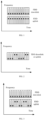
- the 4 th generation mobile communication technology (4G) or 5 th generation mobile communication technology (5G) usually adopt two kinds of duplex modes, one is a frequency division duplex (FDD) mode, as shown in FIG. 1 , and the other is a time division duplex (TDD) mode, as shown in FIG. 2 .
- FDD frequency division duplex
- TDD time division duplex
- the FDD mode generally refers to symmetrical frequency bands, where an uplink frequency band is only provided with uplink services, and a downlink frequency band is only provided with downlink services, and thus the FDD mode is relatively suitable for symmetrical services in uplink and downlink.
- the uplink and downlink services of a user equipment are often asymmetric.
- a flexible duplex mode may be used in the uplink frequency band as shown in FIG. 3 , that is, for the uplink frequency band in the FDD mode, uplink and downlink resources are dynamically allocated, which is similar to the TDD mode; or, the flexible duplex mode may be used in the downlink frequency band as shown in FIG. 4 , that is, for the downlink frequency band in the FDD mode, uplink and downlink resources are dynamically allocated, which is similar to the TDD mode.
- the user equipment may be a user equipment supporting the duplex mode or a user equipment not supporting the duplex mode.
- a way of effectively utilizing capability of the user equipment is a technical problem to be solved.
- embodiments of the present invention provide a method and an apparatus for transmitting capability of a user equipment, and a readable storage medium.
- a method for transmitting capability of a user equipment including: sending first indication information to the user equipment in response to a working frequency band of the user equipment being a frequency division multiplexing frequency band, where the first indication information is configured to instruct the user equipment to report information of a duplex capability corresponding to the working frequency band.
- the network device sends the first indication information to the user equipment to allow the user equipment to report the information of the duplex capability thereof in the working frequency band.
- the network device may flexibly allocate an uplink resource and a downlink resource matched with the duplex capability of the user equipment based on whether the user equipment has the duplex capability and a specific type of the duplex capability, thus improving a utilization efficiency of a frequency spectrum.
- the method further includes: receiving reported information from the user equipment, the reported information being configured to indicate the information of the duplex capability corresponding to the working frequency band for the user equipment.
- the reported information includes a first field, where the first field indicates that the user equipment has the duplex capability in an uplink frequency band and a downlink frequency band of the working frequency band in a case that the first field corresponds to a first value; and the first field indicates that the user equipment does not have the duplex capability in the uplink frequency band and the downlink frequency band of the working frequency band in a case that the first field corresponds to a second value.
- the reported information includes an uplink field and a downlink field, where the uplink field indicates that the user equipment has the duplex capability in an uplink frequency band of the working frequency band in a case that the uplink field corresponds to a third value; the uplink field indicates that the user equipment does not have the duplex capability in the uplink frequency band of the working frequency band in a case that the uplink field corresponds to a fourth value; the downlink field indicates that the user equipment has the duplex capability in a downlink frequency band of the working frequency band in a case that the downlink field corresponds to a fifth value; and the downlink field indicates that the user equipment does not have the duplex capability in the downlink frequency band of the working frequency band in a case that the downlink field corresponds to a sixth value.
- the reported information includes a second field, where the second field indicates that the user equipment does not have the duplex capability in an uplink frequency band and a downlink frequency band of the working frequency band in a case that the second field corresponds to a seventh value; the second field indicates that the user equipment has the duplex capability in the uplink frequency band of the working frequency band and does not have the duplex capability in the downlink frequency band of the working frequency band in a case that the second field corresponds to an eighth value; the second field indicates that the user equipment does not have the duplex capability in the uplink frequency band of the working frequency band and has the duplex capability in the downlink frequency band of the working frequency band in a case that the second field corresponds to a ninth value; and the second field indicates that the user equipment has the duplex capability in the uplink frequency band and the downlink frequency band of the working frequency band in a case that the second field corresponds to a tenth value.
- a transmission position of an uplink carrier is set in the working frequency band in a case that it is learned that the user equipment has the duplex capability in an uplink frequency band of the working frequency band; and in response to using the carrier aggregation or establishing the double link with the user equipment, a transmission position of a downlink carrier is set in the working frequency band in a case that it is learned that the user equipment has the duplex capability in a downlink frequency band of the working frequency band.
- the method further includes: sending resource scheduling information to the user equipment, the resource scheduling information being configured to indicate an uplink resource and a downlink resource that are consistent with the information of the duplex capability.
- a method for transmitting capability of a user equipment including: receiving first indication information from a network device, the first indication information being configured to instruct the user equipment to report information of a duplex capability corresponding to a working frequency band.
- the method further includes: sending reported information to the network device, the reported information being configured to indicate the information of the duplex capability corresponding to the working frequency band for the user equipment.
- the reported information includes a first field, where the first field indicates that the user equipment has the duplex capability in an uplink frequency band and a downlink frequency band of the working frequency band in a case that the first field corresponds to a first value; and the first field indicates that the user equipment does not have the duplex capability in the uplink frequency band and the downlink frequency band of the working frequency band in a case that the first field corresponds to a second value.
- the reported information includes an uplink field and a downlink field, where the uplink field indicates that the user equipment has the duplex capability in an uplink frequency band of the working frequency band in a case that the uplink field corresponds to a third value; the uplink field indicates that the user equipment does not have the duplex capability in the uplink frequency band of the working frequency band in a case that the uplink field corresponds to a fourth value; the downlink field indicates that the user equipment has the duplex capability in a downlink frequency band of the working frequency band in a case that the downlink field corresponds to a fifth value; and the downlink field indicates that the user equipment does not have the duplex capability in the downlink frequency band of the working frequency band in a case that the downlink field corresponds to a sixth value.
- the reported information includes a second field, where the second field indicates that the user equipment does not have the duplex capability in an uplink frequency band and a downlink frequency band of the working frequency band in a case that the second field corresponds to a seventh value; the second field indicates that the user equipment has the duplex capability in the uplink frequency band of the working frequency band and does not have the duplex capability in the downlink frequency band of the working frequency band in a case that the second field corresponds to an eighth value; the second field indicates that the user equipment does not have the duplex capability in the uplink frequency band of the working frequency band and has the duplex capability in the downlink frequency band of the working frequency band in a case that the second field corresponds to a ninth value; and the second field indicates that the user equipment has the duplex capability in the uplink frequency band and the downlink frequency band of the working frequency band in a case that the second field corresponds to a tenth value.
- the method further includes: receiving resource scheduling information from the network device, the resource scheduling information being configured to indicate an uplink resource and a downlink resource that are consistent with the information of the duplex capability.
- a communication apparatus may be used to perform the steps performed by the network device in the above-mentioned first aspect or any possible design of the first aspect.
- the network device may implement functions in the above methods in a form of a hardware structure, a software module, or a hardware structure plus a software module.
- the communication device may include a transceiving module and a processing module coupled to each other, where the transceiving module is configured to support communication of the communication apparatus, and the processing module is used by the communication apparatus to perform processing operations, such as generating information/messages to be sent, or processing received signals to obtain the information/messages.
- the transceiving module is configured to send first indication information to a user equipment in response to a working frequency band of the user equipment being a frequency division multiplexing frequency band, where the first indication information is configured to instruct the user equipment to report information of a duplex capability corresponding to the working frequency band.
- a communication apparatus configured to perform the steps performed by the network device in the above-mentioned second aspect or any possible design of the second aspect.
- the user equipment may implement functions in the above methods in a form of a hardware structure, a software module, or a hardware structure plus a software module.
- the communication apparatus may include a transceiving module and a processing module coupled to each other, where the transceiving module is configured to support communication of the communication apparatus, and the processing module is used by the communication apparatus to perform processing operations, such as generating information/messages to be sent, or processing received signals to obtain the information/messages.
- the transceiving module is configured to receive first indication information from a network device, the first indication information being configured to instruct the user equipment to report information of a duplex capability corresponding to a working frequency band; and further configured to send reported information to the user equipment, the reported information being configured to indicate the information of the duplex capability corresponding to the working frequency band for the user equipment.
- a communication system which may include the communication apparatus described in the third aspect and the communication apparatus described in the fourth aspect.
- the communication apparatus shown in the third aspect may be composed of a software module and/or a hardware component.
- the communication apparatus described in the fourth aspect may be composed of a software module and/or a hardware component.
- a communication device including a processor and a memory
- the memory is configured to store a computer program
- the processor is configured to execute the computer program to implement the method of the first aspect or any possible design of the first aspect.
- a communication device including a processor and a memory
- the memory is configured to store a computer program
- the processor is configured to execute the computer program to implement the method of the second aspect or any possible design of the second aspect.
- a computer readable storage medium having stored therein instructions (or a computer program, a program) that, when invoked and executed by a computer, cause the computer to perform the method of the first aspect or any possible design of the first aspect.
- a computer readable storage medium having stored therein instructions (or a computer program, a program) that, when invoked and executed by a computer, cause the computer to perform the method of the second aspect or any possible design of the second aspect.
- Benefits in the above-mentioned second to ninth aspects and possible designs thereof may be referred to the description of the benefits of the method in the first aspect and any possible design thereof.
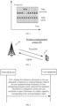
- a method for relaxing a measurement process may be applied to a wireless communication system 100, which may include a user equipment 101 and a network device 102.
- the user equipment 101 is configured to support carrier aggregation, and the user equipment 101 may be connected to a plurality of carrier units of the network device 102, including one primary carrier unit and one or more secondary carrier units.
- the wireless communication system 100 may be applicable to both low frequency and high frequency scenarios.
- Application scenarios of the wireless communication system 100 include, but are not limited to, a long term evolution (LTE) system, an LTE frequency division duplex (FDD) system, an LTE time division duplex (TDD) system, a worldwide interoperability for micro wave access (WiMAX) communication system, a cloud wireless access network (CRAN) system, a future 5th-Generation (5G) system, a new radio (NR) communication system or a future evolved public land mobile network (PLMN) system, etc.
- LTE long term evolution
- FDD frequency division duplex
- TDD LTE time division duplex
- WiMAX worldwide interoperability for micro wave access
- CDRF cloud wireless access network
- 5G future 5th-Generation
- NR new radio
- PLMN future evolved public land mobile network
- the user equipment (UE) 101 shown above may be a terminal, an access terminal, a terminal unit, a terminal station, a mobile station (MS), a remote station, a remote terminal, a mobile terminal, a wireless communication device, a terminal agent or a user equipment, etc.
- the user equipment 101 may be equipped with a wireless transceiving function that may communicate (e.g. wirelessly) with one or more network devices of one or more communication systems and accept network services provided by the network devices, including, but not limited to, the illustrated network device 102.
- the user equipment 101 may be a cellular phone, a cordless phone, a session initiation protocol (SIP) phone, a wireless local loop (WLL) station, a personal digital assistant (PDA) device, a handheld device with a wireless communication function, a computing device or other processing device connected to a wireless modem, an in-vehicle device, a wearable device, a user equipment in the future 5G network or a user equipment in the future evolved PLMN network, etc.
- SIP session initiation protocol
- WLL wireless local loop
- PDA personal digital assistant
- the network device 102 may be an access network device (or an access network point).
- the access network device refers to a device providing a network access function, such as a radio access network (RAN) base station.
- the network device 102 may specifically include a base station (BS), or a radio resource management device including a base station and for controlling the base station.
- the network device 102 may also include a relay station (a relay device), an access point, and the base station in the future 5G network, the base station in the future evolved PLMN network, or an NR base station, etc.
- the network device 102 may be a wearable device or an in-vehicle device.
- the network device 102 may also be a communication chip with a communication module.
- the network device 102 includes, but is not limited to: a next gnodeB (gNB) in the 5G, an evolved node B (eNB) in the LTE system, a radio network controller (RNC), a node B (NB) in a WCDMA system, a radio controller in the CRAN system, a base station controller (BSC), a base transceiver station (BTS) in a GSM or CDMA system, a home evolved nodeB (HNB), a baseband unit (BBU), a transmitting and receiving point (TRP), a transmission point (TP) or a mobile switching center, etc.
- gNB next gnodeB
- eNB evolved node B
- RNC radio network controller
- NB node B
- BSC base station controller
- BTS base transceiver station
- HNB home evolved nodeB
- BBU baseband unit
- TRP transmitting and receiving point
- TP transmission point
- mobile switching center etc.
- Embodiments of the present invention provide a method for transmitting capability of a user equipment. This method is performed by the network device.
- FIG. 6 is a flow chart illustrating a method for transmitting capability of a user equipment according to an embodiment. As shown in FIG. 6 , this method includes the following step.
- first indication information is sent to the user equipment in response to a working frequency band of the user equipment being a frequency division multiplexing frequency band, where the first indication information is configured to instruct the user equipment to report information of a duplex capability corresponding to the working frequency band.
- the network device sends the first indication information to the user equipment to enable the user equipment to report the information of the duplex capability of the user equipment in the working frequency band.
- the network device may flexibly allocate uplink resources and downlink resources matched with the duplex capability of the user equipment based on whether the user equipment has the duplex capability and a specific type of the duplex capability the user equipment has, thus improving a utilization efficiency of the frequency spectrum.
- Embodiments of the present invention provide the method for transmitting the capability of the user equipment. This method is performed by the network device. This method includes: receiving reported information from the user equipment, the reported information being configured to indicate the information of the duplex capability corresponding to the working frequency band for the user equipment.
- the network device sends the first indication information to the user equipment, and receives the reported information from the user equipment to learn the information of the duplex capability corresponding to the working frequency band for the user equipment.
- the network device may flexibly allocate the uplink resources and the downlink resources matched with the duplex capability of the user equipment based on whether the user equipment has the duplex capability and a specific type of the duplex capability the user equipment has, thus improving the utilization efficiency of the frequency spectrum.
- Embodiments of the present invention provide the method for transmitting the capability of the user equipment. This method is performed by the network device. This method includes the following steps.
- the first indication information is sent to the user equipment in response to the working frequency band of the user equipment being the frequency division multiplexing frequency band, where the first indication information is configured to instruct the user equipment to report the information of the duplex capability corresponding to the working frequency band.
- the reported information is received from the user equipment, and the reported information is configured to indicate the information of the duplex capability corresponding to the working frequency band for the user equipment.
- the reported information includes a first field, where the first field indicates that the user equipment has the duplex capability in an uplink frequency band and a downlink frequency band of the working frequency band in a case that the first field corresponds to a first value; and the first field indicates that the user equipment does not have the duplex capability in the uplink frequency band and the downlink frequency band of the working frequency band in a case that the first field corresponds to a second value.
- 1 bit is occupied by the first field in the reported information.
- a value of the first field is 1, it represents that the user equipment has the duplex capability in both the uplink frequency band and the downlink frequency band of the working frequency band.
- the value of the first field is 0, it represents that the user equipment does not have the duplex capability in either the uplink frequency band or the downlink frequency band of the working frequency band.
- Embodiments of the present invention provide the method for transmitting the capability of the user equipment. This method is performed by the network device. This method includes the following steps.
- the first indication information is sent to the user equipment in response to the working frequency band of the user equipment being the frequency division multiplexing frequency band, where the first indication information is configured to instruct the user equipment to report the information of the duplex capability corresponding to the working frequency band.
- the reported information is received from the user equipment, and the reported information is configured to indicate the information of the duplex capability corresponding to the working frequency band for the user equipment.
- the reported information includes an uplink field and a downlink field, where the uplink field indicates that the user equipment has the duplex capability in the uplink frequency band of the working frequency band in a case that the uplink field corresponds to a third value; the uplink field indicates that the user equipment does not have the duplex capability in the uplink frequency band of the working frequency band in a case that the uplink field corresponds to a fourth value; the downlink field indicates that the user equipment has the duplex capability in the downlink frequency band of the working frequency band in a case that the downlink field corresponds to a fifth value; and the downlink field indicates that the user equipment does not have the duplex capability in the downlink frequency band of the working frequency band in a case that the downlink field corresponds to a sixth value.
- 1 bit is occupied by the uplink field in the reported information, and 1 bit is occupied by the downlink field in the reported information.
- a value of the uplink field is 1, it represents that the user equipment has the duplex capability in the uplink frequency band of the working frequency band.
- the value of the uplink field is 0, it represents that the user equipment does not have the duplex capability in the uplink frequency band of the working frequency band.
- a value of the downlink field is 1, it represents that the user equipment has the duplex capability in the downlink frequency band of the working frequency band.
- the value of the downlink field is 0, it represents that the user equipment does not have the duplex capability in the downlink frequency band of the working frequency band.
- the value of the uplink field is 1 and the value of the downlink field is 1, it represents that the user equipment has the duplex capability in both the uplink frequency band and the downlink frequency band of the working frequency band; in a case that the value of the uplink field is 1 and the value of the downlink field is 0, it represents that the user equipment has the duplex capability in the uplink frequency band of the working frequency band and does not have the duplex capability in the downlink frequency band of the working frequency band; in a case that the value of the uplink field is 0 and the value of the downlink field is 1, it represents that the user equipment does not have the duplex capability in the uplink frequency band of the working frequency band and has the duplex capability in the downlink frequency band of the working frequency band; and in a case that the value of the uplink field is 0 and the value of the downlink field is 0, it represents that the user equipment does not have the duplex capability in either the uplink frequency band or the downlink frequency band of the working frequency band.
- Embodiments of the present invention provide the method for transmitting the capability of the user equipment. This method is performed by the network device. This method includes the following steps.
- the first indication information is sent to the user equipment in response to the working frequency band of the user equipment being the frequency division multiplexing frequency band, where the first indication information is configured to instruct the user equipment to report the information of the duplex capability corresponding to the working frequency band.
- the reported information is received from the user equipment, and the reported information is configured to indicate the information of the duplex capability corresponding to the working frequency band from the user equipment.
- the reported information includes a second field, where the second field indicates that the user equipment does not have the duplex capability in the uplink frequency band and the downlink frequency band of the working frequency band in a case that the second field corresponds to a seventh value; the second field indicates that the user equipment has the duplex capability in the uplink frequency band of the working frequency band and does not have the duplex capability in the downlink frequency band of the working frequency band in a case that the second field corresponds to an eighth value; the second field indicates that the user equipment does not have the duplex capability in the uplink frequency band of the working frequency band and has the duplex capability in the downlink frequency band of the working frequency band in a case that the second field corresponds to a ninth value; and the second field indicates that the user equipment has the duplex capability in the uplink frequency band and the downlink frequency band of the working frequency band in a case that the second field corresponds to a tenth value.
- the number of bits occupied by the second field is 2.
- a value of the second field is 11, it represents that the user equipment has the duplex capability in the uplink frequency band and the downlink frequency band of the working frequency band.
- the value of the second field is 10
- the value of the second field is 01, it represents that the user equipment does not have the duplex capability in the uplink frequency band of the working frequency band and has the duplex capability in the downlink frequency band of the working frequency band.
- the value of the second field is 00, it represents that the user equipment does not have the duplex capability in the uplink frequency band and the downlink frequency band of the working frequency band.
- the number of bits occupied by the second field is 2.
- the user equipment has the duplex capability in both the uplink frequency band and the downlink frequency band of the working frequency band.
- the value of the second field is 01, it represents that the user equipment has the duplex capability in the uplink frequency band of the working frequency band and does not have the duplex capability in the downlink frequency band of the working frequency band.
- the user equipment does not have the duplex capability in the uplink frequency band of the working frequency band and has the duplex capability in the downlink frequency band of the working frequency band.
- the value of the second field is 00, it represents that the user equipment does not have the duplex capability in the uplink frequency band and the downlink frequency band of the working frequency band.
- Embodiments of the present invention provide the method for transmitting the capability of the user equipment.
- This method is performed by the network device.
- This method includes the following step. A transmission position of an uplink carrier is set in the working frequency band in a case that it is learned that the user equipment has the duplex capability in the uplink frequency band of the working frequency band, in response to using carrier aggregation or establishing a double link with the user equipment.
- the network device uses the carrier aggregation or establishes the double link with the user equipment, and when network device learns that the user equipment has the duplex capability in the uplink frequency band of the working frequency band, it sets the transmission position of the uplink carrier in the working frequency band (corresponding to a dotted box).
- Embodiments of the present invention provide the method for transmitting the capability of the user equipment.
- This method is performed by the network device.
- This method includes the following step. A transmission position of a downlink carrier is set in the working frequency band in a case that it is learned that the user equipment has the duplex capability in the downlink frequency band of the working frequency band, in response to using the carrier aggregation or establishing the double link with the user equipment.
- the network device uses the carrier aggregation or establishes the double link with the user equipment, and when the network device learns that the user equipment has the duplex capability in the downlink frequency band of the working frequency band, it sets the transmission position of the downlink carrier in the working frequency band (corresponding to a dotted box).
- Embodiments of the present invention provide the method for transmitting the capability of the user equipment. This method is performed by the network device. This method includes: sending resource scheduling information to the user equipment, the resource scheduling information being configured to indicate an uplink resource and a downlink resource that are consistent with the information of the duplex capability.
- allocation of uplink and downlink resources may be performed by statically configuring an uplink and downlink frame structure through radio resource control (RRC) signaling, or may be performed by dynamically adjusting and indicating a ratio of uplink and downlink time slots or a ratio of uplink and downlink orthogonal frequency division multiplexing (OFDM) symbols via medium access control (MAC).
- RRC radio resource control
- OFDM orthogonal frequency division multiplexing
- Embodiments of the present invention provide a method for transmitting capability of a user equipment. This method is performed by the user equipment. This method includes the following step.
- the first indication information is received from a network device, where the first indication information is configured to instruct the user equipment to report information of a duplex capability corresponding to a working frequency band.
- the user equipment receives the first indication information from the network device to trigger the transmission of the reported information to the network device from the user equipment, to allow the network device to learn the information of the duplex capability corresponding to the working frequency band for the user equipment.
- the network device may flexibly allocate the uplink resource and the downlink resource matched with the duplex capability to the user equipment based on whether the user equipment has the duplex capability and a specific type of the duplex capability the user equipment has, thus improving the utilization efficiency of the frequency spectrum.
- Embodiments of the present invention provide the method for transmitting the capability of the user equipment. This method is performed by the user equipment. This method includes: sending reported information to the network device, the reported information being configured to indicate the information of the duplex capability corresponding to the working frequency band for the user equipment
- the user equipment sends the reported information to the network device, so that the network device learns the information of the duplex capability corresponding to the working frequency band for the user equipment.
- the network device may flexibly allocate the uplink resource and the downlink resource matched with the duplex capability to the user equipment based on whether the user equipment has the duplex capability and a specific type of the duplex capability the user equipment has, thus improving the utilization efficiency of the frequency spectrum.
- Embodiments of the present invention provide the method for transmitting the capability of the user equipment. This method is performed by the user equipment. This method includes the following steps.
- the first indication information is received from the network device, where the first indication information is configured to instruct the user equipment to report the information of the duplex capability corresponding to the working frequency band.
- the reported information is sent to the network device, where the reported information is configured to indicate the information of the duplex capability corresponding to the working frequency band for the user equipment.
- the reported information includes the first field, where the first field indicates that the user equipment has the duplex capability in an uplink frequency band and a downlink frequency band of the working frequency band in a case that the first field corresponds to a first value; and the first field indicates that the user equipment does not have the duplex capability in the uplink frequency band and the downlink frequency band of the working frequency band in a case that the first field corresponds to a second value.
- Embodiments of the present invention provide the method for transmitting the capability of the user equipment. This method is performed by the user equipment. This method includes the following steps.
- the first indication information is received from the network device, where the first indication information is configured to instruct the user equipment to report the information of the duplex capability corresponding to the working frequency band.
- the reported information is sent to the network device, where the reported information is configured to indicate the information of the duplex capability corresponding to the working frequency band from the user equipment.
- the reported information includes an uplink field and a downlink field, where the uplink field indicates that the user equipment has the duplex capability in the uplink frequency band of the working frequency band in a case that the uplink field corresponds to a third value; the uplink field indicates that the user equipment does not have the duplex capability in the uplink frequency band of the working frequency band in a case that the uplink field corresponds to a fourth value; the downlink field indicates that the user equipment has the duplex capability in the downlink frequency band of the working frequency band in a case that the downlink field corresponds to a fifth value; and the downlink field indicates that the user equipment does not have the duplex capability in the downlink frequency band of the working frequency band in a case that the downlink field corresponds to a sixth value.
- Embodiments of the present invention provide the method for transmitting the capability of the user equipment. This method is performed by the user equipment. This method includes the following steps.
- the first indication information is received from the network device, where the first indication information is configured to instruct the user equipment to report the information of the duplex capability corresponding to the working frequency band.
- the reported information is sent to the network device, where the reported information is configured to indicate the information of the duplex capability corresponding to the working frequency band for the user equipment.
- the reported information includes a second field, where the second field indicates that the user equipment does not have the duplex capability in the uplink frequency band and the downlink frequency band of the working frequency band in a case that the second field corresponds to a seventh value; the second field indicates that the user equipment has the duplex capability in the uplink frequency band of the working frequency band and does not have the duplex capability in the downlink frequency band of the working frequency band in a case that the second field corresponds to an eighth value; the second field indicates that the user equipment does not have the duplex capability in the uplink frequency band of the working frequency band and has the duplex capability in the downlink frequency band of the working frequency band in a case that the second field corresponds to a ninth value; and the second field indicates that the user equipment has the duplex capability in the uplink frequency band and the downlink frequency band of the working frequency band in a case that the second field corresponds to a tenth value.
- Embodiments of the present invention provide the method for transmitting the capability of the user equipment. This method is performed by the user equipment. This method includes: receiving resource scheduling information from the network device, where the resource scheduling information is configured to indicate an uplink resource and a downlink resource that are consistent with the information of the duplex capability.
- embodiments of the present invention further provide a communication device/apparatus that may have the functions of the network device 102 in the above-described method embodiments and may be used to perform the steps performed by the network device 102 provided by the above-described method embodiments.
- the functions may be implemented by hardware, or may be implemented by software or hardware executing corresponding software.
- the hardware or software includes one or more modules corresponding to the functions described above.
- a communication apparatus 900 is provided as shown in FIG. 9 and may be served as the network device involved in the method embodiments described above and perform the steps performed by the network device in the method embodiments described above.
- the communication apparatus 900 may include a transceiving module 901 and a processing module 902 coupled to each other.
- the transceiving module 901 is configured to support communication of the communication apparatus 900, and the transceiving module 901 has a wireless communication function, for example, the transceiving module 901 may perform wireless communication with other communication devices through a wireless radio.
- the processing module 902 is configured to support the communication apparatus 900 to perform processing operations in the above-described method embodiments, including but not limited to: generating information, messages sent by the transceiving module 901, and/or demodulating and decoding signals received by the transceiving module 901.
- the transceiving module 901 is configured to send the first indication information to the user equipment in response to the working frequency band of the user equipment being the frequency division multiplexing frequency band, where the first indication information is configured to instruct the user equipment to report the information of the duplex capability corresponding to the working frequency band.
- the transceiving module 901 is further configured to receive the reported information from the user equipment, where the reported information is configured to indicate the information of the duplex capability corresponding to the working frequency band from the user equipment.
- the reported information includes the first field, where the first field indicates that the user equipment has the duplex capability in the uplink frequency band and the downlink frequency band of the working frequency band in a case that the first field corresponds to the first value; and the first field indicates that the user equipment does not have the duplex capability in the uplink frequency band and the downlink frequency band of the working frequency band in a case that the first field corresponds to the second value.
- the reported information includes the uplink field and the downlink field, where the uplink field indicates that the user equipment has the duplex capability in the uplink frequency band of the working frequency band in a case that the uplink field corresponds to the third value; the uplink field indicates that the user equipment does not have the duplex capability in the uplink frequency band of the working frequency band in a case that the uplink field corresponds to the fourth value; the downlink field indicates that the user equipment has the duplex capability in the downlink frequency band of the working frequency band in a case that the downlink field corresponds to the fifth value; and the downlink field indicates that the user equipment does not have the duplex capability in the downlink frequency band of the working frequency band in a case that the downlink field corresponds to the sixth value.
- the reported information includes the second field, where the second field indicates that the user equipment does not have the duplex capability in the uplink frequency band and the downlink frequency band of the working frequency band in a case that the second field corresponds to the seventh value; the second field indicates that the user equipment has the duplex capability in the uplink frequency band of the working frequency band and does not have the duplex capability in the downlink frequency band of the working frequency band in a case that the second field corresponds to the eighth value; the second field indicates that the user equipment does not have the duplex capability in the uplink frequency band of the working frequency band and has the duplex capability in the downlink frequency band of the working frequency band in a case that the second field corresponds to the ninth value; and the second field indicates that the user equipment has the duplex capability in both the uplink frequency band and the downlink frequency band of the working frequency band in a case that the second field corresponds to the tenth value.
- the processing module 902 is configured to set the transmission position of the uplink carrier in the working frequency band in a case that it is learned that the user equipment has the duplex capability in the uplink frequency band of the working frequency band, in response to using the carrier aggregation or establishing the double link with the user equipment; and the processing module 902 is configured to set the transmission position of the downlink carrier in the working frequency band in a case that it is learned that the user equipment has the duplex capability in the downlink frequency band of the working frequency band, in response to using the carrier aggregation or establishing the double link with the user equipment.
- the transceiving module 901 is configured to send resource scheduling information to the user equipment, where the resource scheduling information is configured to indicate the uplink resource and the downlink resource that are consistent with the information of the duplex capability.
- a structure thereof may be as shown in FIG. 10 .
- the structure of the communication device is illustrated with a base station as an example.
- a device 1000 includes a memory 1001, a processor 1002, a transceiving component 1003, and a power component 1006.
- the memory 1001 is coupled to the processor 1002 and is configured to store programs and data necessary to implement various functions of the communication device 1000.
- the processor 1002 is configured to support the communication device 1000 to realize the corresponding functions in the method described above, which may be implemented by calling a program stored in the memory 1001.
- the transceiving component 1003 may be a wireless transceiver and is configured to support the communication device 1000 to receive signaling and/or data and transmit signaling and/or data over a wireless radio.
- the transceiving component 1003, which may also be referred to as a transceiving unit or a communication unit, may include a radio component 1004, which may be a remote radio unit (RRU), specifically for transmission of radio frequency signal and conversion of a radio frequency signal to a baseband signal, and one or more antennas 1005, specifically for transmission and reception of the radio frequency signal.
- RRU remote radio unit
- the processor 1002 may perform baseband processing on the data to be transmitted and output the baseband signal to the radio unit, and the radio unit performs radio processing on the baseband signal and then transmits the radio frequency signal in a form of an electromagnetic wave through an antenna.
- the radio unit receives the radio frequency signal through the antenna, converts the radio frequency signal into the baseband signal, and outputs the baseband signal to the processor 1002, and the processor 1002 converts the baseband signal into data and processes the data.
- embodiments of the present invention further provide a communication device/apparatus that may have the functions of the user equipment 101 in the above-described method embodiments and may be used to perform the steps performed by the user equipment 101 provided by the above-described method embodiments.
- the functions may be implemented by hardware, or may be implemented by software or hardware executing corresponding software.
- the hardware or software includes one or more modules corresponding to the functions described above.
- a communication apparatus 1100 is provided as shown in FIG. 11 , and may be served as the user equipment involved in the method embodiments described above and perform the steps performed by the user equipment in the method embodiments described above.
- the communication apparatus 1100 may include a transceiving module 1101 and a processing module 1102 coupled to each other.
- the transceiving module 1101 is configured to support communication of the communication apparatus 1100, and the transceiving module 1101 has the wireless communication function, for example, the transceiving module 1101 may perform the wireless communication with other communication devices through the wireless radio.
- the processing module 1102 may be configured to support the communication apparatus 1100 to perform processing operations in the above-described method embodiments, including, but not limited to: generating information and messages sent by the transceiving module 1101, and/or demodulating and decoding signals received by the transceiving module 1101.
- the transceiving module 1101 is configured to receive the first indication information from the network device, where the first indication information is configured to instruct the user equipment to report the information of the duplex capability corresponding to the working frequency band; and the transceiving module 1101 is further configured to send the reported information to the network device, where the reported information is configured to indicate the information of the duplex capability corresponding to the working frequency band for the user equipment.
- the reported information includes the first field, where the first field indicates that the user equipment has the duplex capability in the uplink frequency band and the downlink frequency band of the working frequency band in a case that the first field corresponds to the first value; and the first field indicates that the user equipment does not have the duplex capability in the uplink frequency band and the downlink frequency band of the working frequency band in a case that the first field corresponds to the second value.
- the reported information includes the uplink field and the downlink field, where the uplink field indicates that the user equipment has the duplex capability in the uplink frequency band of the working frequency band in a case that the uplink field corresponds to the third value; the uplink field indicates that the user equipment does not have the duplex capability in the uplink frequency band of the working frequency band in a case that the uplink field corresponds to the fourth value; the downlink field indicates that the user equipment has the duplex capability in the downlink frequency band of the working frequency band in a case that the downlink field corresponds to the fifth value; and the downlink field indicates that the user equipment does not have the duplex capability in the downlink frequency band of the working frequency band in a case that the downlink field corresponds to the sixth value.
- the reported information includes the second field, where the second field indicates that the user equipment does not have the duplex capability in both the uplink frequency band and the downlink frequency band of the working frequency band in a case that the second field corresponds to the seventh value; the second field indicates that the user equipment has the duplex capability in the uplink frequency band of the working frequency band and does not have the duplex capability in the downlink frequency band of the working frequency band in a case that the second field corresponds to the eighth value; the second field indicates that the user equipment does not have the duplex capability in the uplink frequency band of the working frequency band and has the duplex capability in the downlink frequency band of the working frequency band in a case that the second field corresponds to the ninth value; and the second field indicates that the user equipment has the duplex capability in both the uplink frequency band and the downlink frequency band of the working frequency band in a case that the second field corresponds to the tenth value.
- the transceiving module 1101 is configured to receive the resource scheduling information from the network device, where the resource scheduling information is configured to indicate the uplink resource and the downlink resource that are consistent with the information of the duplex capability.
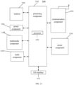
- the device 1200 can be a mobile phone, a computer, a digital broadcast terminal, a messaging device, a game console, a tablet device, a medical device, a fitness device, a personal digital assistant, or the like.
- the device 1200 may include one or more of the following components: a processing component 1202, a memory 1204, a power component 1206, a multimedia component 1208, an audio component 1210, an input/output (I/O) interface 1212, a sensor component 1214, and a communication component 216.
- a processing component 1202 a memory 1204, a power component 1206, a multimedia component 1208, an audio component 1210, an input/output (I/O) interface 1212, a sensor component 1214, and a communication component 216.
- the processing component 1202 typically controls overall operations of the device 1200, such as the operations associated with display, telephone calls, data communications, camera operations, and recording operations.
- the processing component 1202 may include one or more processors 1220 to execute instructions to perform all or part of the steps in the above described methods.
- the processing component 1202 may include one or more modules which facilitate the interaction between the processing component 1202 and other components.
- the processing component 1202 may include a multimedia module to facilitate the interaction between the multimedia component 1208 and the processing component 1202.
- the memory 1204 is configured to store various types of data to support the operation of the device 1200. Examples of such data include instructions for any applications or methods operated on the device 1200, contact data, phonebook data, messages, pictures, video, etc.
- the memory 1204 may be implemented using any type of volatile or non-volatile memory devices, or a combination thereof, such as a static random access memory (SRAM), an electrically erasable programmable read-only memory (EEPROM), an erasable programmable read-only memory (EPROM), a programmable read-only memory (PROM), a read-only memory (ROM), a magnetic memory, a flash memory, a magnetic or optical disk.
- SRAM static random access memory
- EEPROM electrically erasable programmable read-only memory
- EPROM erasable programmable read-only memory
- PROM programmable read-only memory
- ROM read-only memory
- magnetic memory a magnetic memory
- flash memory a flash memory
- magnetic or optical disk a magnetic
- the power component 1206 provides power to various components of the device 1200.
- the power component 1206 may include a power management system, one or more power sources, and any other components associated with generation, management, and distribution of power in the device 1200.
- the multimedia component 1208 includes a screen providing an output interface and located between the device 1200 and the user.
- the screen may include a liquid crystal display (LCD) and a touch panel (TP). If the screen includes the touch panel, the screen may be implemented as a touch screen to receive input signals from the user.
- the touch panel includes one or more touch sensors to sense touches, swipes, and gestures on the touch panel. The touch sensors may not only sense a boundary of a touch or swipe action, but also sense a period of time and a pressure associated with the touch or swipe action.
- the multimedia component 1208 includes a front camera and/or a rear camera.
- the front camera and/or the rear camera may receive an external multimedia datum while the device 1200 is in an operation mode, such as a photographing mode or a video mode.
- an operation mode such as a photographing mode or a video mode.
- Each of the front camera and the rear camera may be a fixed optical lens system or have focus and optical zoom capability.
- the audio component 1210 is configured to output and/or input audio signals.
- the audio component 1210 includes a microphone (MIC) configured to receive an external audio signal when the device 1200 is in an operation mode, such as a call mode, a recording mode, and a voice recognition mode.
- the received audio signal may be further stored in the memory 1204 or transmitted via the communication component 1216.
- the audio component 1210 further includes a speaker to output audio signals.
- the I/O interface 1212 provides an interface between the processing component 1202 and peripheral interface modules, such as a keyboard, a click wheel, buttons, and the like.
- the buttons may include, but are not limited to, a home button, a volume button, a starting button, and a locking button.
- the sensor component 1214 includes one or more sensors to provide status assessments of various aspects of the device 1200. For instance, the sensor component 1214 may detect an open/closed status of the device 1200, relative positioning of components, e.g., the display and the keypad, of the device 1200, a change in position of the device 1200 or a component of the device 1200, a presence or absence of user contact with the device 1200, an orientation or an acceleration/deceleration of the device 1200, and a change in temperature of the device 1200.
- the sensor component 1214 may include a proximity sensor configured to detect the presence of nearby objects without any physical contact.
- the sensor component 1214 may also include a light sensor, such as a CMOS or CCD image sensor, for use in imaging applications.
- the sensor component 1214 may also include an accelerometer sensor, a gyroscope sensor, a magnetic sensor, a pressure sensor, or a temperature sensor.
- the communication component 1216 is configured to facilitate communication, wired or wirelessly, between the device 1200 and other devices.
- the device 1200 can access a wireless network based on a communication standard, such as WiFi, 2G, or 3G, or a combination thereof.
- the communication component 1216 receives a broadcast signal or broadcast associated information from an external broadcast management system via a broadcast channel.
- the communication component 1216 further includes a near field communication (NFC) module to facilitate short-range communications.
- the NFC module may be implemented based on a radio frequency identification (RFID) technology, an infrared data association (IrDA) technology, an ultra-wideband (UWB) technology, a Bluetooth (BT) technology, and other technologies.
- RFID radio frequency identification
- IrDA infrared data association
- UWB ultra-wideband
- BT Bluetooth
- the device 1200 may be implemented with one or more application specific integrated circuits (ASICs), digital signal processors (DSPs), digital signal processing devices (DSPDs), programmable logic devices (PLDs), field programmable gate arrays (FPGAs), controllers, micro-controllers, microprocessors, or other electronic components, for performing the above described methods.
- ASICs application specific integrated circuits
- DSPs digital signal processors
- DSPDs digital signal processing devices
- PLDs programmable logic devices
- FPGAs field programmable gate arrays
- controllers micro-controllers, microprocessors, or other electronic components, for performing the above described methods.
- non-transitory computer-readable storage medium including instructions, such as included in the memory 1204, executable by the processor 1220 in the device 1200, for performing the above-described methods.
- the non-transitory computer-readable storage medium may be a ROM, a RAM, a CD-ROM, a magnetic tape, a floppy disc, an optical data storage device, and the like.
- the network device sends the first indication information to the user equipment to allow the user equipment to report the information of the duplex capability thereof in the working frequency band, so that the network device can flexibly allocate the uplink resource and the downlink resource matched with the duplex capability of the user equipment based on whether the user equipment has the duplex capability and a specific type of the duplex capability the user equipment has, thus improving the utilization efficiency of the frequency spectrum.
Landscapes
- Engineering & Computer Science (AREA)
- Signal Processing (AREA)
- Computer Networks & Wireless Communication (AREA)
- Databases & Information Systems (AREA)
- Mobile Radio Communication Systems (AREA)
Applications Claiming Priority (1)
| Application Number | Priority Date | Filing Date | Title |
|---|---|---|---|
| PCT/CN2021/096158 WO2022246709A1 (fr) | 2021-05-26 | 2021-05-26 | Procédé et appareil de transmission de capacité d'équipement utilisateur, et support de stockage |
Publications (2)
| Publication Number | Publication Date |
|---|---|
| EP4351077A1 true EP4351077A1 (fr) | 2024-04-10 |
| EP4351077A4 EP4351077A4 (fr) | 2025-03-19 |
Family
ID=84229415
Family Applications (1)
| Application Number | Title | Priority Date | Filing Date |
|---|---|---|---|
| EP21942290.4A Pending EP4351077A4 (fr) | 2021-05-26 | 2021-05-26 | Procédé et appareil de transmission de capacité d'équipement utilisateur, et support de stockage |
Country Status (4)
| Country | Link |
|---|---|
| US (1) | US20240251395A1 (fr) |
| EP (1) | EP4351077A4 (fr) |
| CN (1) | CN115707353A (fr) |
| WO (1) | WO2022246709A1 (fr) |
Families Citing this family (1)
| Publication number | Priority date | Publication date | Assignee | Title |
|---|---|---|---|---|
| EP4718764A1 (fr) * | 2023-05-23 | 2026-04-01 | Beijing Xiaomi Mobile Software Co., Ltd. | Procédé et appareil de transmission d'informations, dispositif de communication et support de stockage |
Family Cites Families (14)
| Publication number | Priority date | Publication date | Assignee | Title |
|---|---|---|---|---|
| US7962161B1 (en) * | 2007-11-21 | 2011-06-14 | L-3 Communications Corp. | Method and apparatus for FDD and TDD terminal entry into a wireless communication network |
| WO2010076376A1 (fr) * | 2008-12-30 | 2010-07-08 | Nokia Corporation | Techniques de rapport de bandes de fréquence à support pour réseaux sans fil |
| KR101990134B1 (ko) * | 2011-08-10 | 2019-06-17 | 삼성전자주식회사 | 듀얼 모드 단말의 성능 정보 보고 방법 및 장치 |
| KR101920496B1 (ko) * | 2011-11-25 | 2018-11-21 | 애플 인크. | 인터밴드 tdd 전송 방식에서 사용자 단말의 전송 모드 정보를 송수신하는 방법 및 장치 |
| CN103209403A (zh) * | 2012-01-13 | 2013-07-17 | 中兴通讯股份有限公司 | 用户设备能力查询、上报方法及装置 |
| JP6282831B2 (ja) * | 2013-09-26 | 2018-02-21 | 株式会社Nttドコモ | ユーザ端末、基地局及び無線通信方法 |
| US9655121B2 (en) * | 2014-05-09 | 2017-05-16 | Samsung Electronics Co., Ltd. | Method and apparatus for transmitting and receiving UE capability information in mobile communication system |
| WO2015177398A1 (fr) * | 2014-05-20 | 2015-11-26 | Nokia Technologies Oy | Commande d'authentification de réseau cellulaire |
| US9949269B2 (en) * | 2014-08-15 | 2018-04-17 | Telefonaktiebolaget Lm Ericsson (Publ) | Conditional network capabilities for improved system performance |
| CN105553605B (zh) * | 2014-11-04 | 2019-04-05 | 中国电信股份有限公司 | 通信方法、系统以及基站和终端 |
| CN105407511B (zh) * | 2015-10-23 | 2018-11-30 | 中国联合网络通信集团有限公司 | 一种用户设备接入载波聚合网络的方法及装置 |
| WO2017111821A1 (fr) * | 2015-12-26 | 2017-06-29 | Intel Corporation | Capacité duplex intégral sur des équipements d'utilisateur et des stations de base |
| CN110022592B (zh) * | 2019-04-22 | 2021-11-26 | 维沃移动通信有限公司 | 一种网络接入方法、移动终端及服务器 |
| US11764936B2 (en) * | 2020-07-06 | 2023-09-19 | Qualcomm Incorporated | Intelligent switching between duplexing modes in wireless communication |
-
2021
- 2021-05-26 EP EP21942290.4A patent/EP4351077A4/fr active Pending
- 2021-05-26 WO PCT/CN2021/096158 patent/WO2022246709A1/fr not_active Ceased
- 2021-05-26 US US18/563,657 patent/US20240251395A1/en active Pending
- 2021-05-26 CN CN202180001599.9A patent/CN115707353A/zh active Pending
Also Published As
| Publication number | Publication date |
|---|---|
| EP4351077A4 (fr) | 2025-03-19 |
| CN115707353A (zh) | 2023-02-17 |
| US20240251395A1 (en) | 2024-07-25 |
| WO2022246709A1 (fr) | 2022-12-01 |
Similar Documents
| Publication | Publication Date | Title |
|---|---|---|
| EP4418725A1 (fr) | Procédé et appareil d'envoi ou de réception d'informations d'indication de capacité, et dispositif et support | |
| US20250220581A1 (en) | Method and device for monitoring wake-up signal and readable storage medium | |
| EP4625864A1 (fr) | Procédé et appareil de transmission d'informations de capacité, et support d'enregistrement lisible | |
| US20250150810A1 (en) | Terminal capability transmission method and apparatus, and readable storage medium | |
| CN116636250B (zh) | 一种测量方法、装置、设备及可读存储介质 | |
| CN117917104B (zh) | 一种传输能力信息的方法、装置以及可读存储介质 | |
| CN115004822B (zh) | 一种上行切换的方法、装置及可读存储介质 | |
| US20250220459A1 (en) | Method for transmitting measurement configuration information, apparatus and readable storage medium | |
| CN113841458B (zh) | 一种传输时频资源配置信息的方法、装置及可读存储介质 | |
| CN117256181A (zh) | 一种传输信号质量阈值信息的方法、装置及可读存储介质 | |
| US20240251395A1 (en) | Method for transmitting capability of user equipment | |
| CN116746258B (zh) | 一个确定信道接入方式的方法、装置及存储介质 | |
| CN115191138B (zh) | 一种传输时域资源配置信息的方法、装置及可读存储介质 | |
| CN114938711B (zh) | 一种传输用户设备能力的方法、装置及可读存储介质 | |
| EP4554288A1 (fr) | Procédé et appareil de transmission d'informations d'instruction, ainsi que support d'enregistrement lisible | |
| CN115606289B (zh) | 一种传输harq-ack的方法、装置及可读存储介质 | |
| US20250063412A1 (en) | Measurement method and apparatus, device, and readable storage medium | |
| CN117480806A (zh) | 一种传输能力指示信息的方法、装置、及可读存储介质 | |
| US20260012830A1 (en) | Measurement method and apparatus, and device and readable storage medium | |
| CN115244890B (zh) | 一种传输配置信息的方法、装置及可读存储介质 | |
| JP7738753B2 (ja) | アンライセンスアップリンクチャネルの検出ビームを決定する方法、装置及び媒体 | |
| US20250081203A1 (en) | Monitoring method and device, and readable storage medium | |
| CN116261907B (zh) | 一种接收及发送上行信道配置信息的方法、装置及介质 | |
| US20250386348A1 (en) | Method and apparatus for transmitting resource configuration information, and readable storage medium | |
| EP4319368A1 (fr) | Procédé et appareil de transmission d'informations d'intervalle de planification et support de stockage lisible |
Legal Events
| Date | Code | Title | Description |
|---|---|---|---|
| STAA | Information on the status of an ep patent application or granted ep patent |
Free format text: STATUS: THE INTERNATIONAL PUBLICATION HAS BEEN MADE |
|
| PUAI | Public reference made under article 153(3) epc to a published international application that has entered the european phase |
Free format text: ORIGINAL CODE: 0009012 |
|
| STAA | Information on the status of an ep patent application or granted ep patent |
Free format text: STATUS: REQUEST FOR EXAMINATION WAS MADE |
|
| 17P | Request for examination filed |
Effective date: 20231206 |
|
| AK | Designated contracting states |
Kind code of ref document: A1 Designated state(s): AL AT BE BG CH CY CZ DE DK EE ES FI FR GB GR HR HU IE IS IT LI LT LU LV MC MK MT NL NO PL PT RO RS SE SI SK SM TR |
|
| DAV | Request for validation of the european patent (deleted) | ||
| DAX | Request for extension of the european patent (deleted) | ||
| A4 | Supplementary search report drawn up and despatched |
Effective date: 20250217 |
|
| RIC1 | Information provided on ipc code assigned before grant |
Ipc: H04W 8/24 20090101ALI20250211BHEP Ipc: H04L 5/14 20060101AFI20250211BHEP |