EP4351122A1 - Informationsverarbeitungsvorrichtung und informationsverarbeitungsverfahren - Google Patents
Informationsverarbeitungsvorrichtung und informationsverarbeitungsverfahren Download PDFInfo
- Publication number
- EP4351122A1 EP4351122A1 EP22811414.6A EP22811414A EP4351122A1 EP 4351122 A1 EP4351122 A1 EP 4351122A1 EP 22811414 A EP22811414 A EP 22811414A EP 4351122 A1 EP4351122 A1 EP 4351122A1
- Authority
- EP
- European Patent Office
- Prior art keywords
- spectroscopic
- display
- photographing
- color
- information processing
- Prior art date
- Legal status (The legal status is an assumption and is not a legal conclusion. Google has not performed a legal analysis and makes no representation as to the accuracy of the status listed.)
- Pending
Links
- 230000010365 information processing Effects 0.000 title claims abstract description 252
- 238000003672 processing method Methods 0.000 title claims description 4
- 238000006243 chemical reaction Methods 0.000 claims abstract description 281
- 238000004611 spectroscopical analysis Methods 0.000 claims abstract description 253
- 238000003384 imaging method Methods 0.000 claims abstract description 198
- 238000009826 distribution Methods 0.000 claims abstract description 35
- 230000035945 sensitivity Effects 0.000 claims abstract description 25
- 238000012545 processing Methods 0.000 claims description 135
- 238000003860 storage Methods 0.000 claims description 27
- 238000000611 regression analysis Methods 0.000 claims description 8
- 238000004364 calculation method Methods 0.000 description 68
- 238000005286 illumination Methods 0.000 description 50
- 238000012986 modification Methods 0.000 description 43
- 230000004048 modification Effects 0.000 description 43
- 238000010586 diagram Methods 0.000 description 40
- 238000004891 communication Methods 0.000 description 36
- 239000003086 colorant Substances 0.000 description 29
- 238000000034 method Methods 0.000 description 23
- 239000011159 matrix material Substances 0.000 description 21
- 230000006870 function Effects 0.000 description 11
- 238000005516 engineering process Methods 0.000 description 7
- 239000000284 extract Substances 0.000 description 7
- 238000005259 measurement Methods 0.000 description 5
- 230000010354 integration Effects 0.000 description 3
- 239000004065 semiconductor Substances 0.000 description 3
- 230000000694 effects Effects 0.000 description 2
- 238000005401 electroluminescence Methods 0.000 description 2
- 238000000926 separation method Methods 0.000 description 2
- 241000282412 Homo Species 0.000 description 1
- 238000013459 approach Methods 0.000 description 1
- 230000010485 coping Effects 0.000 description 1
- 238000012937 correction Methods 0.000 description 1
- 238000007689 inspection Methods 0.000 description 1
- 239000004973 liquid crystal related substance Substances 0.000 description 1
- 238000010801 machine learning Methods 0.000 description 1
- 238000004519 manufacturing process Methods 0.000 description 1
- 230000003287 optical effect Effects 0.000 description 1
- 230000001151 other effect Effects 0.000 description 1
- 238000007639 printing Methods 0.000 description 1
- 238000001228 spectrum Methods 0.000 description 1
Images


Classifications
-
- G—PHYSICS
- G01—MEASURING; TESTING
- G01J—MEASUREMENT OF INTENSITY, VELOCITY, SPECTRAL CONTENT, POLARISATION, PHASE OR PULSE CHARACTERISTICS OF INFRARED, VISIBLE OR ULTRAVIOLET LIGHT; COLORIMETRY; RADIATION PYROMETRY
- G01J3/00—Spectrometry; Spectrophotometry; Monochromators; Measuring colours
- G01J3/46—Measurement of colour; Colour measuring devices, e.g. colorimeters
- G01J3/462—Computing operations in or between colour spaces; Colour management systems
-
- G—PHYSICS
- G01—MEASURING; TESTING
- G01J—MEASUREMENT OF INTENSITY, VELOCITY, SPECTRAL CONTENT, POLARISATION, PHASE OR PULSE CHARACTERISTICS OF INFRARED, VISIBLE OR ULTRAVIOLET LIGHT; COLORIMETRY; RADIATION PYROMETRY
- G01J3/00—Spectrometry; Spectrophotometry; Monochromators; Measuring colours
- G01J3/28—Investigating the spectrum
- G01J3/2823—Imaging spectrometer
-
- G—PHYSICS
- G01—MEASURING; TESTING
- G01J—MEASUREMENT OF INTENSITY, VELOCITY, SPECTRAL CONTENT, POLARISATION, PHASE OR PULSE CHARACTERISTICS OF INFRARED, VISIBLE OR ULTRAVIOLET LIGHT; COLORIMETRY; RADIATION PYROMETRY
- G01J3/00—Spectrometry; Spectrophotometry; Monochromators; Measuring colours
- G01J3/46—Measurement of colour; Colour measuring devices, e.g. colorimeters
-
- H—ELECTRICITY
- H04—ELECTRIC COMMUNICATION TECHNIQUE
- H04N—PICTORIAL COMMUNICATION, e.g. TELEVISION
- H04N1/00—Scanning, transmission or reproduction of documents or the like, e.g. facsimile transmission; Details thereof
- H04N1/46—Colour picture communication systems
- H04N1/56—Processing of colour picture signals
- H04N1/60—Colour correction or control
- H04N1/6083—Colour correction or control controlled by factors external to the apparatus
- H04N1/6086—Colour correction or control controlled by factors external to the apparatus by scene illuminant, i.e. conditions at the time of picture capture, e.g. flash, optical filter used, evening, cloud, daylight, artificial lighting, white point measurement, colour temperature
-
- H—ELECTRICITY
- H04—ELECTRIC COMMUNICATION TECHNIQUE
- H04N—PICTORIAL COMMUNICATION, e.g. TELEVISION
- H04N1/00—Scanning, transmission or reproduction of documents or the like, e.g. facsimile transmission; Details thereof
- H04N1/46—Colour picture communication systems
- H04N1/56—Processing of colour picture signals
- H04N1/60—Colour correction or control
- H04N1/6083—Colour correction or control controlled by factors external to the apparatus
- H04N1/6088—Colour correction or control controlled by factors external to the apparatus by viewing conditions, i.e. conditions at picture output
-
- H—ELECTRICITY
- H04—ELECTRIC COMMUNICATION TECHNIQUE
- H04N—PICTORIAL COMMUNICATION, e.g. TELEVISION
- H04N23/00—Cameras or camera modules comprising electronic image sensors; Control thereof
- H04N23/80—Camera processing pipelines; Components thereof
- H04N23/84—Camera processing pipelines; Components thereof for processing colour signals
Definitions
- the present disclosure relates to an information processing apparatus and an information processing method.
- a display method a plurality of videos displayed on a reference monitor are photographed by a camera, and a correspondence relationship between an RGB value of an image photographed by the camera and an XYZ value of the video is held.
- the RGB value obtained by photographing a subject by using the reference monitor as a light source are converted into the XYZ value based on the held correspondence relationship and displayed on the reference monitor, so that the color of the subject on a photographing side is reproduced on the reference monitor.
- Patent Literature 1 JP 2015-177484 A
- the conventional display method has a problem in that the color of the subject on the photographing side is more easily reproduced on the monitor (display side).
- the present disclosure provides a mechanism that can more easily reproduce the color of the subject on the photographing side on the display side.
- an information processing apparatus includes a control unit.
- the control unit acquires characteristic data related to a spectroscopic sensitivity characteristic of an imaging apparatus.
- the control unit acquires photographing-side spectroscopic data related to a spectroscopic distribution characteristic of a light source in a photographing environment in which the imaging apparatus performs imaging.
- the control unit acquires color spectroscopic data related to a spectroscopic reflectance characteristic of a predetermined color.
- the control unit calculates an RGB value output by the imaging apparatus when imaging of the predetermined color is performed by using the imaging apparatus by using the characteristic data, the photographing-side spectroscopic data, and the color spectroscopic data.
- the control unit acquires display-side spectroscopic data related to a spectroscopic distribution characteristic of a light source in a display environment in which imaged data imaged by the imaging apparatus is displayed on a display apparatus.
- the control unit calculates an XYZ value when the predetermined color is displayed on the display apparatus by using the display-side spectroscopic data and the color spectroscopic data.
- the control unit calculates conversion information for converting the RGB value into the XYZ value.
- One or a plurality of embodiments (including examples and modifications) described below can each be implemented independently. On the other hand, at least some of the plurality of embodiments described below may be appropriately combined with at least some of other embodiments.
- the plurality of embodiments may include novel features different from each other. Therefore, the plurality of embodiments can contribute to solving different objects or problems, and can exhibit different effects.
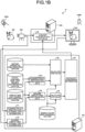
- FIG. 1A is a diagram for describing an outline of an information processing system 10 according to an embodiment of the present disclosure.
- the information processing system 10 includes an information processing apparatus 100, a conversion apparatus 200, an imaging apparatus 300, and a display apparatus 500.
- the imaging apparatus 300 is a camera that photographs an image of a subject 400 by using a photographing-side illumination apparatus 600A as a photographing-side light source and generates an imaged image.
- the imaging apparatus 300 may photograph a moving image of the subject 400 or may photograph a still image.
- the display apparatus 500 is an apparatus that displays the imaged image photographed by the imaging apparatus 300 to an observer (not illustrated).
- the display apparatus 500 displays the imaged image to the observer by using a display-side illumination apparatus 600B as a display-side light source.
- an imaged image obtained by photographing a patient in a hospital A is displayed on a monitor (display apparatus 500) of a hospital B, and a doctor (observer) performs an examination.
- a doctor observeer
- the doctor can examine the patient in the hospital A in the same manner as in the case of being in the hospital B.
- the information processing system 10 acquires the color coordinates of the subject 400 and the photographing-side illumination apparatus 600A as the XYZ value. As a result, the information processing system 10 can hold the absolute coordinates of the color from imaging by the imaging apparatus 300 to display by the display apparatus 500.
- the imaging apparatus 300 needs to be an apparatus that generates an imaged image of the XYZ value. That is, the imaging apparatus 300 needs to be an apparatus called a so-called XYZ camera imitating spectroscopic characteristics of human eyes.
- the XYZ camera is expensive and not common.
- an imaged image (hereinafter, also referred to as an RGB image) of an RGB value is imaged by using the imaging apparatus 300 (so-called RGB camera) that images RGB images.
- the conversion apparatus 200 performs conversion processing of converting the RGB value of the RGB image into the XYZ value, thereby acquiring the imaged image of the XYZ value.
- the information processing apparatus 100 generates conversion information used for conversion processing by the conversion apparatus 200. For example, when displaying the RGB image imaged by the imaging apparatus 300 on the display apparatus 500, the information processing apparatus 100 generates conversion information for displaying the same color as the color visually recognized when the observer directly observes the subject 400 on the display apparatus 500.
- the information processing system 10 in FIG. 1A is a system that estimates the color of the subject 400 visually recognized in a case where the display-side illumination apparatus 600B is used as a light source, from the imaged image imaged by the imaging apparatus 300 by using the photographing-side illumination apparatus 600A as a light source and reproduces it on the display apparatus 500.
- a color reproduction system that estimates and reproduces a color under a predetermined light source based on an RGB image
- a system disclosed in JP 2001-8220 A is known.
- Such a color reproduction system estimates a color of a subject under predetermined illumination light by using statistical data of spectroscopic reflectance of the subject.
- the color estimation of the subject is performed with high accuracy by switching the statistical data according to a photographing signal of the subject.
- the color estimation of the subject is performed by using statistical data based on a prescribed illumination light spectrum. Therefore, for example, in a case where the illumination light on the photographing side on which the subject is photographed is changed or the illumination light on the observation side where the monitor is installed is changed, there is a concern that the accuracy of the color estimation of the subject is deteriorated.
- the color estimation is performed by using the statistical data of the spectroscopic reflectance of the subject, but the spectroscopic reflectance is held in units of 1 nm between 380 nm and 780 nm in a visible range.
- the system holds 400 pieces of data per color, and the amount of operation for calculating the statistical data becomes very large. Therefore, there is a concern that a system needs to be constructed by using special hardware for performing the operation. Alternatively, there is a concern that the system can only perform color estimation of a still image instead of a moving image.
- the proposed technology of the present disclosure provides a mechanism capable of more easily reproducing the color of the subject on the photographing side on the monitor in the color reproduction system technology of reproducing the color of the subject on the photographing side on the monitor (display apparatus) on the display side.
- the information processing apparatus 100 of the information processing system 10 calculates conversion information for converting the photographed image (RGB image) into a display image (converted image). For example, the information processing apparatus 100 acquires characteristic data related to a spectroscopic sensitivity characteristic of the imaging apparatus 300.
- the information processing apparatus 100 acquires imaging-side spectroscopic data related to a spectroscopic distribution characteristic of a light source (for example, the photographing-side illumination apparatus 600A) in an imaging environment in which the imaging apparatus 300 performs imaging.
- the information processing apparatus 100 acquires color spectroscopic data related to a spectroscopic reflectance characteristic of a predetermined color (sample color).
- the information processing apparatus 100 uses the acquired characteristic data, imaging-side spectroscopic data, and color spectroscopic data to calculate an RGB value output by the imaging apparatus 300 in a case where a sample color is photographed by using the imaging apparatus 300.
- the information processing apparatus 100 acquires display-side spectroscopic data related to a spectroscopic distribution characteristic of a light source (for example, the display-side illumination apparatus 600B) in a display environment in which the display apparatus 500 is displayed.
- the information processing apparatus 100 calculates an XYZ value in a case where the sample color is displayed on the display apparatus 500 by using the acquired display-side spectroscopic data and color spectroscopic data.
- the information processing apparatus 100 calculates conversion information for converting the calculated RGB value into an XYZ value.
- the color reproduction system can be applied to an inspection system in the factory. More specifically, for example, the color reproduction system technology of the proposed technology of the present disclosure can be applied in a case where the color or the like of a product manufactured in a factory is confirmed at a remote place.
- FIG. 1B is a diagram for describing an outline of information processing according to an embodiment of the present disclosure.
- Such information processing is processing of generating conversion information used for conversion from an RGB image (imaged image) into an XYZ image (display image) performed by the conversion apparatus 200.
- the information processing apparatus 100 acquires photographing-side external light information from an external light sensor (not illustrated) mounted on the imaging apparatus 300 (step S1).
- the photographing-side external light information can include, for example, information related to the photographing-side illumination apparatus 600A.
- the information processing apparatus 100 acquires display-side external light information from an external light sensor (not illustrated) mounted on the display apparatus 500 (step S2).
- the display-side external light information can include, for example, information related to the display-side illumination apparatus 600B.
- the information processing apparatus 100 acquires the imaging-side spectroscopic data related to the spectroscopic distribution characteristic of the photographing-side illumination apparatus 600A from a photographing-side light source spectroscopic data DB based on the acquired photographing-side external light information (step S3).
- the information processing apparatus 100 acquires the display-side spectroscopic data related to the spectroscopic distribution characteristic of the display-side illumination apparatus 600B from a display-side light source spectroscopic data DB (step S4).
- the information processing apparatus 100 calculates an RGB value based on characteristic data acquired from an imaging apparatus spectroscopic data DB, the photographing-side spectroscopic data acquired in step S3, and the color spectroscopic data acquired from a sample color spectroscopic data DB (step S5).
- the characteristic data is information related to the spectroscopic sensitivity characteristic of the imaging apparatus 300.
- the color spectroscopic data is information related to a spectroscopic reflectance characteristic of a predetermined sample color.
- the color spectroscopic data may include information related to spectroscopic reflectance characteristics of a plurality of (for example, 1000 to 2000 colors) sample colors.
- the information processing apparatus 100 calculates an RGB value output by the imaging apparatus 300 when the subject 400 of a sample color is imaged under the photographing-side illumination apparatus 600A, based on the characteristic data, the photographing-side spectroscopic data, and the color spectroscopic data.
- the information processing apparatus 100 calculates the RGB value for each of a plurality of sample colors.
- the information processing apparatus 100 calculates an XYZ value based on the display-side spectroscopic data acquired in step S4 and the color spectroscopic data acquired from the sample color spectroscopic data DB (step S6).
- the information processing apparatus 100 calculates the XYZ value to be displayed on the display apparatus 500 based on the display-side spectroscopic data and the color spectroscopic data.
- the information processing apparatus 100 calculates the XYZ value for each of a plurality of sample colors.
- the information processing apparatus 100 calculates conversion information for converting an RGB image into an XYZ image based on the RGB value calculated in step S5 and the XYZ value calculated in step S6 (step S7).
- the conversion information is, for example, information that associates the RGB value with the XYZ value for each of the plurality of sample colors. Details of the conversion information will be described later.
- the conversion apparatus 200 converts the RGB value of the image imaged by the imaging apparatus 300 into a converted image of the XYZ value by using the conversion information calculated by the information processing apparatus 100 (step S8), and displays the converted image on the display apparatus 500.
- the conversion apparatus 200 outputs the converted image of the XYZ value to the display apparatus 500.
- the conversion apparatus 200 may convert the converted image of the XYZ value into a converted image of the RGB value and output the converted image to the display apparatus 500.
- the conversion from the RGB image into the converted image of the XYZ value by the conversion apparatus 200 is performed for each pixel of the RGB image in units of frames.
- the calculation of the conversion information performed by the information processing apparatus 100 can be performed, for example, in a case where the photographing-side illumination apparatus 600A or the display-side illumination apparatus 600B is switched or in a case where a color sample (color sample) including a plurality of sample colors is switched.
- the color sample can be switched according to a type of the subject 400, such as a skin color of a person. That is, in a case where the type of an imaging target of the imaging apparatus 300 is switched, the color spectroscopic data of the color sample can be switched, but in general, the possibility of switching the color sample is low, and it is considered that the color sample is fixed.
- the information processing apparatus 100 performs information processing of calculating the conversion information at a predetermined cycle, for example, in units of several seconds.
- the information processing system 10 images the spectroscopy of the subject 400 including the photographing-side light source (photographing-side illumination apparatus 600A) with the imaging apparatus 300 to acquire the RGB image.
- the information processing system 10 converts the acquired RGB image into absolute color coordinates XYZ under the display-side light source (display-side illumination apparatus 600B) by using the conversion information.
- the information processing system 10 according to the present embodiment since the spectroscopic reflectance of the subject 400 is not estimated, the amount of operation required for conversion can be reduced.
- the conversion information is calculated based on the color spectroscopic data of the sample color and the like. As described above, such conversion information may be recalculated, for example, when the photographing-side illumination apparatus 600A or the display-side illumination apparatus 600B is switched. Therefore, the amount of operation performed by the information processing system 10 according to the present embodiment can be further reduced, and the color of the subject 400 on the photographing side can be more easily reproduced on the display apparatus 500.
- the information processing system 10 calculates the conversion information by using, for example, the photographing-side external light information and the display-side external light information acquired from the external light sensor. Therefore, the information processing system 10 can easily update the conversion information even in a case where the illumination apparatus is switched after introduction of the system, and can change the conversion information more flexibly.
- the photographing-side illumination apparatus 600A and the display-side illumination apparatus 600B will be described.
- the photographing-side illumination apparatus 600A and the display-side illumination apparatus 600B are also simply referred to as an illumination apparatus 600.
- the illumination apparatus 600 is used as a light source of the information processing system 10.
- the illumination apparatus 600 for example, an incandescent lamp, a fluorescent lamp, a light emitting diode (LED), or the like can be used. Further, instead of the illumination apparatus 600, sunlight may be used as the light source of the information processing system 10.
- the photographing-side light source may be the same type of light source as the display-side light source, or may be a different type of light source. Furthermore, there may be a case where the photographing-side light source and the display-side light source are the same, such as a case where the imaging apparatus 300 and the display apparatus 500 are disposed in the same environment, for example, disposed in one room.
- FIG. 2 is a block diagram illustrating a configuration example of the imaging apparatus 300 according to the embodiment of the present disclosure.
- the imaging apparatus 300 illustrated in FIG. 2 includes a communication unit 310, an imaging unit 320, and an external light sensor 330.
- the communication unit 310 is a communication interface that communicates with an external apparatus via a network in a wired or wireless manner.
- the communication unit 310 is realized by, for example, a network interface card (NIC) or the like.
- the imaging unit 320 images the subject 400 to generate an imaged image (RGB image).
- the imaging unit 320 is, for example, an image sensor.
- the imaging unit 320 images and generates, for example, a moving image or a still image.
- the imaging unit 320 outputs the imaged image to the conversion apparatus 200 via the communication unit 310.
- the external light sensor 330 is an apparatus that acquires information of an imaging-side light source.
- the external light sensor 330 includes, for example, a plurality of color sensors (not illustrated).
- the plurality of color sensors are, for example, sensors that separate and extract light (color components) having different wavelengths.
- the external light sensor 330 separates light in a human visible range (380 nm to 780 nm in wavelength) into a plurality of light beams for different wavelengths by using the plurality of color sensors. In this manner, the external light sensor 330 performs filter spectroscopic processing to separate and extract light having a predetermined wavelength.
- the external light sensor 330 outputs the separation result to the information processing apparatus 100 via the communication unit 310, for example.
- the external light sensor 330 performs the spectroscopy by using the plurality of color sensors.
- the external light sensor 330 may be, for example, a sensor that acquires the spectroscopy of the light source in more detail, such as a spectrometer. In this manner, by using the spectrometer, the light source estimation processing by the information processing apparatus 100 described later can be omitted.
- the spectrometer is expensive and not common, the external light sensor 330 can be configured more inexpensively and more easily by using the color sensor.
- the imaging apparatus 300 has the external light sensor 330, but the present disclosure is not limited thereto. It is sufficient that the information related to the photographing-side light source is acquired by the external light sensor 330, and for example, the external light sensor 330 may be disposed independently on the photographing side separately from the imaging apparatus 300.
- FIG. 3 is a block diagram illustrating a configuration example of the conversion apparatus 200 and the display apparatus 500 according to the embodiment of the present disclosure.
- the conversion apparatus 200 is an information processing apparatus that converts the RGB image acquired by the imaging apparatus 300 into a converted image of the color absolute coordinate XYZ value under the display-side light source and displays the converted image on the display apparatus 500.
- the conversion apparatus 200 illustrated in FIG. 3 includes a communication unit 210, a storage unit 220, and a control unit 230.
- the communication unit 210 is a communication interface that communicates with an external apparatus via a network in a wired or wireless manner.
- the communication unit 210 is realized by, for example, a network interface card (NIC) or the like.
- the storage unit 220 is a storage apparatus capable of reading and writing data, such as a DRAM, an SRAM, a flash memory, or a hard disk.
- the storage unit 220 functions as a storage unit of the conversion apparatus 200.
- the storage unit 220 stores conversion information to be used for conversion processing performed by the control unit 230 described later.
- the control unit 230 controls each unit of the conversion apparatus 200.
- the control unit 230 is realized, for example, by executing a program stored in the conversion apparatus 200 by a central processing unit (CPU), a micro processing unit (MPU), a graphics processing unit (GPU), or the like using a random access memory (RAM) or the like as a work area.
- the control unit 230 is realized by, for example, an integrated circuit such as an application specific integrated circuit (ASIC), or a field programmable gate array (FPGA).
- ASIC application specific integrated circuit
- FPGA field programmable gate array
- the control unit 230 includes a conversion information acquisition unit 231, a conversion processing unit 232, and a display control unit 233.
- Each block (the conversion information acquisition unit 231 to the display control unit 233) constituting the control unit 230 is a functional block indicating a function of the control unit 230.
- These functional blocks may be software blocks or hardware blocks.
- each of the functional blocks described above may be one software module realized by software (including microprograms), or may be one circuit block on a semiconductor chip (die).
- each functional block may be one processor or one integrated circuit.
- the control unit 230 may be configured by a functional unit different from the above-described functional block. A configuration method of the functional block is arbitrary.
- control unit 230 may be configured by a functional unit different from the above-described functional block.
- some or all of the operations of the blocks (the conversion information acquisition unit 231 to the display control unit 233) constituting the control unit 230 may be performed by another apparatus.
- some or all of the operations of the blocks constituting the control unit 230 may be performed by a control apparatus realized by cloud computing.
- the conversion information acquisition unit 231 acquires conversion information from the information processing apparatus 100 via the communication unit 210, and stores the conversion information in, for example, the storage unit 220.
- the conversion information acquisition unit 231 acquires the conversion information at a predetermined cycle of several seconds, for example.
- the conversion information is information for converting the RGB image imaged by the imaging apparatus 300 into a converted image of the color absolute coordinate XYZ value under the display-side light source, and is expressed by, for example, a conversion coefficient, a look up table (LUT), or the like.
- the conversion processing unit 232 executes conversion processing of converting the RGB image acquired from the imaging apparatus 300 via the communication unit 210 into a converted image of the color absolute coordinate XYZ value by using the conversion information.
- the conversion processing unit 232 outputs the converted image to the display control unit 233. Note that details of the conversion processing will be described later.
- the display control unit 233 controls the display apparatus 500 to display the converted image.
- the converted image of the XYZ value generated by the conversion processing unit 232 is output to the display apparatus 500.
- the display control unit 233 converts the converted image of the XYZ value generated by the conversion processing unit 232 into a converted image of the RGB value and outputs the converted image to the display apparatus 500. Note that information for converting the converted image from the XYZ value into the RGB value is assumed to be stored in the storage unit 220 in advance.
- the display apparatus 500 is, for example, a display apparatus such as a liquid crystal display (LCD) or an organic electro luminescence (EL) display.
- the display apparatus 500 displays the converted image output by the conversion apparatus 200.
- the display apparatus 500 may convert the converted image of the XYZ value into the RGB value and then display the converted image on the display.
- the display apparatus 500 illustrated in FIG. 3 includes an external light sensor 510.
- the external light sensor 3510 is an apparatus that acquires information of a display-side light source.
- the external light sensor 510 has, for example, a plurality of color sensors (not illustrated).
- the plurality of color sensors are, for example, sensors that separate and extract light (color components) having different wavelengths.
- the external light sensor 510 separates light in a human visible range (380 nm to 780 nm in wavelength) into a plurality of light beams for different wavelengths by using the plurality of color sensors. In this manner, the external light sensor 510 performs filter spectroscopic processing to separate and extract light having a predetermined wavelength.
- the external light sensor 510 outputs the separation result to the information processing apparatus 100.
- the external light sensor 510 performs spectroscopy by using a plurality of color sensors
- the external light sensor 510 is not limited thereto.
- the external light sensor 510 may be, for example, a sensor that acquires the spectroscopy of the light source in more detail, such as a spectrometer. In this manner, by using the spectrometer, the light source estimation processing by the information processing apparatus 100 described later can be omitted.
- the spectrometer is expensive and not common, the external light sensor 510 can be configured more inexpensively and more easily by using the color sensor.
- the display apparatus 500 has the external light sensor 510, but the present disclosure is not limited thereto.
- Information related to the display-side light source may be acquired by the external light sensor 510.
- the external light sensor 510 may be disposed independently on the display side separately from the display apparatus 500, and in a case where the conversion apparatus 200 is disposed on the display side, the external light sensor 510 may be mounted on the conversion apparatus 200.
- FIG. 4 is a block diagram illustrating a configuration example of the information processing apparatus 100 according to the embodiment of the present disclosure.
- the information processing apparatus 100 includes a communication unit 110, a storage unit 120, and a control unit 130.
- the communication unit 110 is a communication interface that communicates with an external apparatus via a network in a wired or wireless manner.
- the communication unit 110 is realized by, for example, a network interface card (NIC) or the like.
- the storage unit 120 is a storage apparatus capable of reading and writing data, such as a DRAM, an SRAM, a flash memory, or a hard disk.
- the storage unit 120 functions as a storage unit of the information processing apparatus 100.
- the storage unit 120 has an imaging apparatus spectroscopic data DB 121, a photographing-side light source spectroscopic data DB 122, a display-side light source spectroscopic data DB 123, and a sample color spectroscopic data DB 124.
- the imaging apparatus spectroscopic data DB 121 holds characteristic data related to the spectroscopic sensitivity characteristic of the imaging apparatus 300.
- the imaging apparatus spectroscopic data DB 121 holds, for example, characteristic data of a plurality of the imaging apparatuses 300.
- the information processing apparatus 100 acquires the characteristic data of the imaging apparatus 300 actually mounted on the information processing system 10 from the imaging apparatus spectroscopic data DB 121.
- the imaging apparatus spectroscopic data DB 121 desirably comprehensively holds the characteristic data of all the imaging apparatuses 300 that can be employed in the information processing system 10.
- the imaging apparatus spectroscopic data DB 121 may hold characteristic data of the imaging apparatus 300 determined in advance.
- the photographing-side light source spectroscopic data DB 122 holds photographing-side (imaging-side) spectroscopic data related to a spectroscopic distribution characteristic of the photographing-side light source.
- the photographing-side light source spectroscopic data DB 122 holds, for example, photographing-side spectroscopic data of a plurality of photographing-side illumination apparatuses 600A.
- the photographing-side light source spectroscopic data DB 122 desirably comprehensively holds spectroscopic data of a light source that can be a photographing-side light source, such as an incandescent lamp, a fluorescent lamp, an LED, or sunlight.
- the display-side light source spectroscopic data DB 123 holds display-side (observation side) spectroscopic data related to a spectroscopic distribution characteristic of the display-side light source.
- the display-side light source spectroscopic data DB 123 holds, for example, photographing-side spectroscopic data of a plurality of display-side illumination apparatuses 600B.
- the display-side light source spectroscopic data DB 123 desirably comprehensively holds spectroscopic data of a light source that can be a display-side light source, such as an incandescent lamp, a fluorescent lamp, an LED, or sunlight.
- the light source spectroscopic data DB is divided between the photographing side and the display side, but the present disclosure is not limited thereto.
- the photographing-side light source spectroscopic data DB 122 and the display-side light source spectroscopic data DB 123 may be configured as one DB.
- the sample color spectroscopic data DB 124 holds color spectroscopic data related to a spectroscopic reflectance characteristic of a sample color.
- the color spectroscopic data includes, for example, a spectroscopic reflectance for each of a plurality of sample colors included in a color sample (color sample).
- the sample color included in the color spectroscopic data desirably covers the color gamut required in the conversion processing from the RGB value into the XYZ value. That is, the color spectroscopic data desirably includes a large number of spectroscopic reflectance data covering the color gamut necessary for the conversion processing.
- the sample color spectroscopic data DB 124 may hold color spectroscopic data for each of a plurality of color samples (color samples) according to, for example, a type of the subject 400.
- the sample color spectroscopic data DB 124 holds color spectroscopic data for each representative object in nature based on printing color samples of about 1000 to 2000 colors.
- the sample color spectroscopic data DB 124 may hold color spectroscopic data of the sample colors that are dense in the vicinity of the color of which color reproduction accuracy is to be improved, that is, the number of samples is large in the vicinity of the color of which color reproduction accuracy is to be improved. That is, the sample color included in the color spectroscopic data may be a different color for each corresponding object.
- the information processing apparatus 100 can further improve the color reproduction accuracy and control the deviation of the color reproduction accuracy due to the sample color for each object to some extent.
- the spectroscopic reflectance included in the color spectroscopic data may be an actual spectroscopic reflectance of the object, or may be an imaginary spectroscopic reflectance (estimated spectroscopic reflectance) created (estimated) as data based on the actual spectroscopic reflectance.
- the control unit 130 controls each unit of the information processing apparatus 100.
- the control unit 130 is realized, for example, by executing a program stored in the information processing apparatus 100 by a central processing unit (CPU), a micro processing unit (MPU), a graphics processing unit (GPU), or the like using a random access memory (RAM) or the like as a work area.
- the control unit 130 may be realized by, for example, an integrated circuit such as an application specific integrated circuit (ASIC) and a field programmable gate array (FPGA).
- ASIC application specific integrated circuit
- FPGA field programmable gate array
- the control unit 130 includes an external light information acquisition unit 131, a spectroscopic data acquisition unit 132, an RGB value calculation unit 133, an XYZ value calculation unit 134, and a conversion information calculation unit 135.
- Each block (the external light information acquisition unit 131 to the conversion information calculation unit 135) constituting the control unit 130 is a functional block indicating a function of the control unit 130.
- These functional blocks may be software blocks or hardware blocks.
- each of the functional blocks described above may be one software module realized by software (including microprograms), or may be one circuit block on a semiconductor chip (die).
- each functional block may be one processor or one integrated circuit.
- the control unit 130 may be configured by a functional unit different from the above-described functional block. A configuration method of the functional block is arbitrary.
- control unit 130 may be configured by a functional unit different from the above-described functional block.
- some or all of the operations of the blocks (the external light information acquisition unit 131 to the conversion information calculation unit 135) constituting the control unit 130 may be performed by another apparatus.
- some or all of the operations of the blocks constituting the control unit 130 may be performed by a control apparatus realized by cloud computing.
- the external light information acquisition unit 131 acquires photographing-side external light information from the external light sensor 330 of the imaging apparatus 300 via the communication unit 110.
- the external light information acquisition unit 131 acquires display-side external light information from the external light sensor 510 of the display apparatus 500 via the communication unit 110.
- the external light information acquisition unit 131 outputs the acquired photographing-side external light information and display-side external light information to the spectroscopic data acquisition unit 132.
- the spectroscopic data acquisition unit 132 acquires photographing-side spectroscopic data from the photographing-side light source spectroscopic data DB 122 based on the photographing-side external light information acquired from the external light information acquisition unit 131.
- the spectroscopic data acquisition unit 132 acquires display-side spectroscopic data from the display-side light source spectroscopic data DB 123 based on the display-side external light information acquired from the external light information acquisition unit 131. Details of a method of acquiring the photographing-side spectroscopic data and the display-side spectroscopic data by the spectroscopic data acquisition unit 132 will be described later with reference to FIG. 5 .
- the RGB value calculation unit 133 calculates an RGB value output by the imaging apparatus 300 under the photographing-side light source for each sample color based on the characteristic data of the imaging apparatus 300, the photographing-side spectroscopic data, and the color spectroscopic data of the sample color.
- the RGB value calculation unit 133 acquires the characteristic data of the imaging apparatus 300 from the imaging apparatus spectroscopic data DB 121 according to the imaging apparatus 300 that actually performs imaging.
- the RGB value calculation unit 133 acquires the photographing-side spectroscopic data from the spectroscopic data acquisition unit 132.
- the RGB value calculation unit 133 acquires, for example, color spectroscopic data corresponding to the type of the subject 400 from the sample color spectroscopic data DB 124.
- the RGB value calculation unit 133 calculates the RGB value by switching the characteristic data according to the imaging apparatus 300. Further, the RGB value calculation unit 133 calculates the RGB value by switching the color spectroscopic data according to the subject 400.
- the RGB value calculation unit 133 outputs the calculated RGB value to the conversion information calculation unit 135.
- the XYZ value calculation unit 134 calculates an XYZ value under the display-side light source for each sample color based on the display-side spectroscopic data and the color spectroscopic data of the sample color.
- the XYZ value calculation unit 134 acquires, for example, color spectroscopic data corresponding to the type of the subject 400 from the sample color spectroscopic data DB 124. Thus, the XYZ value calculation unit 134 calculates the XYZ value by switching the color spectroscopic data according to the subject 400.
- the XYZ value calculation unit 134 outputs the calculated XYZ value to the conversion information calculation unit 135.
- the conversion information calculation unit 135 calculates conversion information by using the RGB value calculated by the RGB value calculation unit 133 and the XYZ value calculated by the XYZ value calculation unit 134.
- the conversion information is, for example, information for associating the RGB value with the XYZ value for each sample color included in the color sample. Details of the conversion information and the calculation processing of the conversion information will be described later.
- the conversion information calculation unit 135 calculates (updates) the conversion information at a predetermined cycle (several seconds), for example.
- the conversion information calculation unit 135 outputs the conversion information to the conversion apparatus 200 via the communication unit 110.
- FIG. 5 is a diagram illustrating a configuration example of the spectroscopic data acquisition unit 132 according to the embodiment of the present disclosure. Note that, in FIG. 5 , a case where the spectroscopic data acquisition unit 132 estimates the photographing-side light source will be described, but the spectroscopic data acquisition unit 132 similarly estimates the display-side light source.
- the spectroscopic data acquisition unit 132 illustrated in FIG. 5 includes a filter spectroscopic processing unit 1321 and a comparison and estimation processing unit 1322.
- the filter spectroscopic processing unit 1321 acquires spectroscopic data of a plurality of light sources held by the photographing-side spectroscopic data DB as a plurality of spectroscopic data candidates.
- the filter spectroscopic processing unit 1321 extracts light having the same wavelength as the light (color component) extracted by the external light sensor 330 from the spectroscopic data candidates. That is, the filter spectroscopic processing unit 1321 performs the same filter spectroscopic processing as that of the external light sensor 330 on the spectroscopic data candidates, and outputs the processing result to the comparison and estimation processing unit 1322. Note that the filter spectroscopic processing unit 1321 performs the same filter spectroscopic processing as that of the external light sensor 330, for example, by operation.
- the comparison and estimation processing unit 1322 compares the filter spectroscopic processing results for the plurality of spectroscopic data candidates with the photographing-side external light information acquired by the external light information acquisition unit 131.
- a type for example, a fluorescent lamp, an LED, an incandescent lamp, or the like
- a spectroscopic shape is substantially determined. Therefore, when the light sources are the same, the result of the filter spectroscopic processing on the spectroscopic data of the light source is theoretically the same as the result of the filter spectroscopic processing on the actual light source.
- the comparison and estimation processing unit 1322 compares the filter spectroscopic processing results for the plurality of spectroscopic data candidates with the photographing-side external light information including the filter spectroscopic processing result for the actual light source.
- the comparison and estimation processing unit 1322 estimates that a spectroscopic data candidate corresponding to the filter spectroscopic processing result closest to the filter spectroscopic processing result for the actual light source is the photographing-side spectroscopic data, and estimates that the light source corresponding to the photographing-side spectroscopic data is the actual light source.
- the comparison and estimation processing unit 1322 compares the two filter spectroscopic processing results by calculating how much the filter spectroscopic processing result for the spectroscopic data candidate corresponds to the filter spectroscopic processing result for the actual light source by using a method such as regression analysis, for example.
- the comparison and estimation processing unit 1322 outputs the estimated spectroscopic data candidate of the light source to the RGB value calculation unit 133 as the photographing-side spectroscopic data.
- FIG. 6 is a diagram for describing an example of conversion information according to the embodiment of the present disclosure.
- the conversion information is calculated by the conversion information calculation unit 135 (see FIG. 4 ).
- the conversion information calculation unit 135 mathematically calculates a color coordinate conversion coefficient as the conversion information by comparing the RGB value acquired from the RGB value calculation unit 133 with the XYZ value acquired from the XYZ value calculation unit 134.
- the RGB value calculation unit 133 calculates an RGB value for each sample color.
- sample colors, sample color IDs, and the 4-bit RGB value are illustrated in association with one another.
- the XYZ value calculation unit 134 calculates the XYZ value for each sample color.
- the sample color ID for identifying a sample color and 4-bit RGB value are illustrated in association with each other.
- the conversion information calculation unit 135 compares the RGB value having the same sample color ID with the XYZ value, and calculates a conversion coefficient for converting the RGB value into the XYZ value value. For example, when conversion from the RGB value into the XYZ value is performed by matrix operation, a conversion matrix for converting the RGB value into the XYZ value is calculated.
- the conversion information calculation unit 135 calculates a conversion matrix x1 for converting an RGB value "2F1" with a sample color ID of "0001" into an XYZ value "2D3".
- the conversion matrix x1 is, for example, a 3 ⁇ 3 matrix.
- the conversion information calculation unit 135 calculates conversion matrices x2 to x2000 corresponding to the sample color IDs "0002" to "2000". As described above, the conversion information calculation unit 135 calculates, for example, the conversion matrix x corresponding to all the sample colors included in the color sample (color sample).
- the conversion matrix x calculated by the conversion information calculation unit 135 is different for each sample color. Therefore, the conversion information calculation unit 135 calculates, as the conversion information, a representative conversion matrix X that can average express the conversion from the RGB value into the XYZ value in all sample colors by using, for example, a least squares method or the like, and outputs the representative conversion matrix X to the conversion apparatus 200.
- the conversion apparatus 200 can convert the RGB image into the converted image by simple matrix operation, and the operation amount of the conversion processing can be reduced.
- the conversion apparatus 200 can be configured by simple hardware.
- the number of representative conversion matrices included in the conversion information can be appropriately set according to, for example, a configuration of the conversion apparatus 200, a required processing time, a required conversion accuracy, and the like.
- the conversion information calculation unit 135 sets some points according to color, luminance, or the like, and calculates the representative conversion matrix (coefficient) for each set point, instead of calculating the representative conversion matrix (coefficient) for each pixel. That is, the conversion information calculation unit 135 divides the sample color into a plurality of groups according to color, luminance, and the like, for example, and calculates the representative conversion matrix for each group.
- the conversion apparatus 200 selects a representative conversion matrix according to each pixel value of the RGB image, and performs conversion processing for each pixel. At this time, the conversion apparatus 200 may perform correction on the representative conversion matrix, such as weighting the representative conversion matrix selected according to the pixel value.
- the conversion information calculated by the conversion information calculation unit 135 is not limited to the conversion matrix (conversion coefficient).
- the conversion information calculation unit 135 may calculate a conversion table as the conversion information.
- FIG. 7 is a diagram illustrating an example of conversion information calculated by the conversion information calculation unit 135 according to the embodiment of the present disclosure. As illustrated in FIG. 7 , the conversion information calculation unit 135 calculates a conversion table in which 4-bit RGB value and 4-bit XYZ value are associated with each sample color as the conversion information.
- the conversion information calculation unit 135 may calculate a conversion table in which the RGB value and the XYZ value are associated with each other in all sample colors, or may calculate a conversion table in which the RGB value and the XYZ value are discretely associated with each other in some sample colors.
- the number of sample colors included in the conversion table can be appropriately set according to, for example, the configuration of the conversion apparatus 200, the required processing time, the required conversion accuracy, and the like.
- FIG. 8 is a diagram for describing an example of conversion processing by the conversion apparatus 200 according to the embodiment of the present disclosure. Note that the conversion processing is executed by the conversion processing unit 232 of the conversion apparatus 200. In addition, it is assumed that the conversion table is acquired from the information processing apparatus 100 by the conversion information acquisition unit 231 (see FIG. 3 ) and stored in the storage unit 220 (see FIG. 3 ).
- the conversion processing unit 232 includes a read control unit 2321 and an interpolation processing unit 2322.
- the read control unit 2321 controls read processing of the conversion table according to each pixel value of the RGB image. In a case where there is an RGB value that is the same as the pixel value, the read control unit 2331 performs read processing of the conversion table so as to output an XYZ value corresponding to the RGB value.
- the read control unit 2331 performs read processing of the conversion table so as to output an XYZ value corresponding to the RGB value close to the pixel value.
- one or a plurality of (for example, two) XYZ values may be output.
- the interpolation processing unit 2322 performs interpolation processing by using the XYZ value output by the read control unit 2321, converts the pixel value of the RGB image into the XYZ value, and generates a converted image.
- the interpolation processing unit 2322 does not perform the interpolation processing, for example, and generates a converted image by using the XYZ value corresponding to the RGB value as the pixel value.
- a pixel value of a predetermined pixel of an RGB image is "004".
- the read control unit 2321 performs read processing so as to output an XYZ value "005" corresponding to the RGB value "004".
- the interpolation processing unit 2322 generates a converted image in which the read XYZ value "005" is set as the pixel value of the predetermined pixel.
- the interpolation processing unit 2322 performs interpolation processing on the output XYZ value to generate a converted image.
- a pixel value of a predetermined pixel of an RGB image is "002". As illustrated in FIG. 8 , the same RGB value is not included in the conversion table.
- the read control unit 2321 performs read processing so as to output the XYZ value "001" corresponding to an RGB value "000” and the XYZ value "005" corresponding to the RGB value "004".
- the interpolation processing unit 2322 sets the XYZ values values calculated by performing the interpolation processing based on the read XYZ values "001" and "005" as the pixel values of the predetermined pixels.
- the conversion processing unit 232 generates a converted image obtained by converting each pixel value into an XYZ value by referring to the conversion table for each pixel of the RGB image and performing interpolation processing as necessary.
- FIG. 9 is a flowchart illustrating a flow of an example of information processing executed by the information processing apparatus 100 according to the embodiment of the present disclosure.
- the information processing apparatus 100 executes conversion information calculation processing for calculating conversion information as the information processing.
- the information processing apparatus 100 executes the conversion information calculation processing at a predetermined cycle, for example.
- the information processing apparatus 100 acquires external light information (step S101).
- the information processing apparatus 100 acquires photographing-side external light information from the external light sensor 330, and acquires display-side external light information from the external light sensor 510.
- the information processing apparatus 100 selects spectroscopic data (step S102).
- the information processing apparatus 100 selects photographing-side spectroscopic data corresponding to the photographing-side light source from the photographing-side light source spectroscopic data DB 122 based on the photographing-side external light information.
- the information processing apparatus 100 selects display-side spectroscopic data corresponding to the display-side light source from the display-side light source spectroscopic data DB 123 based on the display-side external light information.
- the information processing apparatus 100 calculates an RGB value (step S103).
- the information processing apparatus 100 calculates the RGB value for each of a plurality of sample colors based on the characteristic data, the photographing-side spectroscopic data, and the color spectroscopic data of the imaging apparatus 300.
- the information processing apparatus 100 calculates an XYZ value (step S104).
- the information processing apparatus 100 calculates the XYZ value for each of a plurality of sample colors based on the display-side spectroscopic data and the color spectroscopic data.
- the information processing apparatus 100 calculates conversion information based on the RGB value and the XYZ value (step S105).
- the conversion information is information used for conversion processing from the RGB value into the XYZ value executed by the conversion apparatus 200, and includes, for example, a conversion coefficient such as a conversion matrix, a conversion table, and the like.
- FIG. 10 is a flowchart illustrating a flow of an example of conversion processing executed by the conversion apparatus 200 according to the embodiment of the present disclosure.
- the conversion apparatus 200 executes the conversion processing while the imaging apparatus 300 is performing imaging.
- the conversion apparatus 200 acquires conversion information from the information processing apparatus 100 (step S201).
- the conversion apparatus 200 may acquire the conversion information before the imaging apparatus 300 starts imaging.
- the conversion apparatus 200 acquires an RGB image from the imaging apparatus 300 (step S202).
- the conversion apparatus 200 converts an RGB value into an XYZ value in each pixel of the acquired RGB image (step S203).
- the conversion apparatus 200 calculates a pixel value of the XYZ value by multiplying each pixel value of the RGB image by a conversion coefficient.
- the conversion coefficient is included in, for example, the conversion information.
- the conversion apparatus 200 outputs a converted image generated in step S203 to the display apparatus 500 (step S204). As a result, the converted image is displayed on the display apparatus 500.
- the conversion apparatus 200 determines whether the conversion information has been updated (step S205). For example, the conversion apparatus 200 determines whether the conversion information has been updated according to whether the conversion information has been acquired from the information processing apparatus 100. Alternatively, the conversion apparatus 200 may determine whether the conversion information has been updated according to whether a predetermined period has elapsed.
- step S205 When it is determined that the conversion information has been updated (step S205; Yes), the conversion apparatus 200 updates change information stored in the storage unit 220 (step S206).
- the conversion apparatus 200 determines whether the imaging of the imaging apparatus 300 has ended (step S207). For example, in a case where a notification of imaging end is received from the imaging apparatus 300 or in a case where communication with the imaging apparatus 300 ends, the conversion apparatus 200 determines that imaging has ended.
- step S207; No When it is determined that the imaging has not ended (step S207; No), the processing returns to step S202. On the other hand, when it is determined that the imaging has ended (step S207; Yes), the processing ends.
- the information processing apparatus 100 calculates the RGB value in a case where the sample color is imaged by the imaging apparatus 300 under the photographing-side light source.
- the information processing apparatus 100 calculates the XYZ value in a case where the sample color is displayed on the display apparatus 500 under the display-side light source.
- the information processing apparatus 100 calculates conversion information for converting the calculated RGB value into the XYZ value.
- the conversion apparatus 200 converts the RGB image imaged by the imaging apparatus 300 into a converted image of the XYZ value by using the conversion information, and displays the converted image on the display apparatus 500.
- the information processing system 10 can hold the color coordinates from photographing to display. Therefore, the information processing system 10 can more easily reproduce the color of the subject 400 on the photographing side on the display apparatus 500 (monitor).
- the information processing system 10 is provided with the external light sensors 330 and 510 on the photographing side and the display side, estimates the spectroscopy of the light source, and acquires spectroscopic data. Therefore, the observer can visually recognize the subject 400 displayed on the display apparatus 500 without being conscious of the spectroscopy of the light source, the change in the light source, and the like.
- the information processing system 10 only needs to update the conversion information in a case where the spectroscopy of the light source changes, and for example, only needs to update the conversion information every several seconds.
- the information processing apparatus 100 can be realized by software.
- the information processing system 10 calculates the conversion information based on the sample color. Therefore, the operation for each pixel can be further reduced as compared with a case where the conversion information is calculated for each pixel imaged by the imaging apparatus 300. As a result, the performance of the hardware required for constructing the information processing system 10 can be further reduced.
- the information processing apparatus 100 is realized by, for example, cloud computing, and the conversion apparatus 200 is disposed on the display side. Therefore, the imaging apparatus 300 and the display apparatus 500 can be easily coupled via an existing network such as the Internet. As described above, the information processing system 10 can be easily applied to a system that confirms a photographed image at a remote place. However, as described above, the information processing apparatus 100 calculates the RGB value by using the characteristic data of the imaging apparatus 300.
- the information processing apparatus 100 acquires information related to the imaging apparatus 300, such as model information of the imaging apparatus 300, from the imaging side (for example, the imaging apparatus 300), for example, with metadata or the like.
- the present disclosure is not limited thereto.
- the information processing system 10 includes the imaging apparatus on the display side and the display apparatus on the imaging side and images are bidirectionally transmitted and received, it is possible to more easily reproduce and display the color of the imaged subject.
- the information processing apparatus 100 estimates the light source based on the external light information acquired from the external light sensors 330 and 510, but the present disclosure is not limited thereto.
- a user who constructs the information processing system 10 an imaging person who performs imaging, or an observer who visually recognizes the converted image on the display apparatus 500 may specify the light source.
- the information processing apparatus 100 acquires spectroscopic data of the designated light source from the spectroscopic data DB.
- the designated light source may be different from the actual light source.
- the actual photographing-side light source is an illumination apparatus
- the user designates sunlight as the light source on the photographing side, so that the user can confirm the color in a case where the subject 400 is outdoors.
- the information processing system 10 can present, for example, a video in a case where imaging is performed in an environment different from an actual photographing environment to the observer.
- the external light sensors 330 and 510 may be omitted.
- the information processing apparatus 100 is an apparatus different from the conversion apparatus 200.
- the conversion apparatus 200 can be disposed on the same display side as the display apparatus 500.
- the information processing apparatus 100 can be realized by, for example, cloud computing.
- the information processing apparatus 100 and the conversion apparatus 200 may be disposed at the same place.
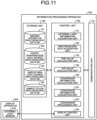
- the functions of the information processing apparatus 100 and the conversion apparatus 200 may be realized by one information processing apparatus 700.
- FIG. 11 is a block diagram illustrating a configuration example of the information processing apparatus 700 according to a second modification of the embodiment of the present disclosure.
- the information processing apparatus 700 illustrated in FIG. 11 includes a communication unit 110, a storage unit 720, and a control unit 730. Note that among the configurations of the information processing apparatus 700 illustrated in FIG. 11 , the same components as those of the information processing apparatus 100 and the conversion apparatus 200 are denoted by the same reference numerals, and description thereof is omitted.
- the storage unit 720 holds, for example, each DB held by the storage unit 120 of the information processing apparatus 100 and information held by the storage unit 220 of the conversion apparatus 200.
- the control unit 730 has, for example, each function of the control unit 130 of the information processing apparatus 100 and each function of the control unit 230 of the conversion apparatus 200.
- each function of the information processing apparatus 100 and the conversion apparatus 200 can be realized as one apparatus.
- the information processing apparatus 700 by disposing the information processing apparatus 700 on the same display side as the display apparatus 500, it becomes easy to respond to an instruction by the observer such as designation of a light source from the observer (see the first modification).
- FIG. 11 illustrates a case where the information processing apparatus 700 is disposed on the same display side as the display apparatus 500 is illustrated, the present disclosure is not limited thereto.
- the information processing apparatus 700 may be realized by cloud computing.
- the observer is on the display side, but the present disclosure is not limited thereto.
- condition color matching pair For example, in a case where colors of two objects are measured by a colorimeter, there is a case where measurement results indicate the same color even when spectroscopic characteristics of the two objects are different (condition color matching pair).
- the colorimeter may indicate the same color. The colorimeter imitates the spectroscopic characteristic of human eyes on average, but actual spectroscopic characteristic of the human eyes varies from individual to individual. Therefore, in the condition color matching pair, different observers may not view the same color due to individual variation.
- the all-white spectroscopic characteristic means a spectroscopic characteristic when a white image is displayed on the display apparatus 500.
- the spectroscopic characteristic viewed by the photographing-side observer has substantially the same shape as the spectroscopic characteristic reproduced by the display apparatus 500. Therefore, it is possible to reduce the influence of the observer variation between the photographing-side observer and the display-side observer.
- the influence of the observer variation is the condition color matching
- the information processing system 10 having a small influence of the variation can be more easily constructed.
- the photographing-side light source is selected in advance so that the spectroscopic characteristic of the photographing-side light source and the all-white spectroscopic characteristic of the display apparatus 500 approach each other, whereby the influence of the observer variation can be reduced.
- the photographing-side illumination apparatus 600A As a specific method of aligning the spectroscopic characteristic of the photographing-side light source (the photographing-side illumination apparatus 600A) and the all-white spectroscopic characteristic of the display apparatus 500, for example, there is a method of using the same apparatus as the display apparatus 500 as the photographing-side light source. In this case, by displaying white (all white) on the same apparatus as the display apparatus 500, the apparatus can be used as illumination (photographing-side light source).
- the information processing apparatus 100 may acquire information of the display apparatus 500 and present the acquired information to the photographing-side observer.
- the information processing apparatus 100 presents information related to, for example, a display mounted on the imaging apparatus 300, a display apparatus disposed on the photographing side, and the like.
- the information processing apparatus 100 may present such information to the photographing-side observer by voice or the like.
- the information processing apparatus 100 can urge the photographing-side observer to change the photographing-side light source to a light source having a spectroscopic characteristic close to the all-white spectroscopic characteristic of the display apparatus 500.
- the information processing apparatus 100 acquires, for example, identification information for identifying the display apparatus 500, such as a model number, from the display apparatus 500.
- the information processing apparatus 100 can present the acquired identification information to the photographing-side observer.
- the information processing apparatus 100 may present the presentation information acquired by using the identification information to the photographing-side observer.
- the presentation information may include, for example, at least one of the following information.
- the light source information may include information related to a display apparatus having an all-white spectroscopic characteristic close to an all-white spectroscopic characteristic of the display apparatus 500 in addition to the information related to the illumination apparatus.
- the types of the light source that can be selected as the photographing-side light source increase.
- the information processing apparatus 100 acquires the presentation information associated with the display apparatus 500 by searching a database constructed in advance.
- This database may be constructed by, for example, a system administrator, or may be constructed based on information collected from a product home page or the like.
- the information processing apparatus 100 presents information to the photographing-side observer, but the present disclosure is not limited thereto.
- the information processing apparatus 100 may present information to the display-side observer, or may present information to both the display-side observer and the photographing-side observer.
- the information processing apparatus 100 may display such information on the display apparatus 500.
- the display-side observer who has received the presentation of the information can change the photographing-side light source by notifying the photographing-side observer of the information.
- the photographing-side light source is changed in accordance with the all-white spectroscopic characteristic of the display apparatus 500, but the present disclosure is not limited thereto.
- the display apparatus 500 may be changed in accordance with the spectroscopic characteristic of the photographing-side light source.
- the display apparatus 500 may be changed to the same display that can be prepared on the photographing side.
- the information processing apparatus 100 presents information related to the photographing-side light source to the display-side observer.
- the information processing apparatus 100 may present both the information related to the display apparatus 500 and the information related to the photographing-side light source to both the display side and the photographing-side observers. In this case, the information processing apparatus 100 can urge the observer to change at least one of the photographing-side apparatus and the display-side apparatus (the display apparatus or the illumination apparatus).
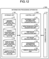
- FIG. 12 is a block diagram illustrating a configuration example of the information processing apparatus 100A according to the fourth modification of the embodiment of the present disclosure. Note that the same components as those of the information processing apparatus 100 illustrated in FIG. 4 are denoted by the same reference numerals, and description thereof is omitted.
- a control unit 130A of the information processing apparatus 100A includes an error calculation unit 136.
- the error calculation unit 136 estimates an error that occurs at the time of conversion processing of the conversion apparatus 200, and displays an estimation result on the display apparatus 500, for example.
- FIG. 13 is a block diagram illustrating a configuration example of the error calculation unit 136 according to the fourth modification of the embodiment of the present disclosure.
- the error calculation unit 136 illustrated in FIG. 13 includes a conversion processing unit 1361, an error estimation unit 1362, and a display information generation unit 1363.
- the conversion processing unit 1361 converts the RGB value calculated by the RGB value calculation unit 133 into an XYZ value.
- the error estimation unit 1362 compares the XYZ value (hereinafter, also referred to as converted XYZ value) converted by the conversion processing unit 1361 with the XYZ value (hereinafter, also referred to as calculated XYZ value) calculated by the XYZ value calculation unit 134 to estimate an error.
- the error estimation unit 1362 calculates, as the error, a difference ( ⁇ x) in an X component and a difference ( ⁇ y) in a Y component between the converted XYZ value and the calculated XYZ value.
- the error estimation unit 1362 may calculate an average value, a maximum value, a standard deviation, and the like in all sample colors included in the color sample (color sample) as the error by using DE 2000 or the like of color difference calculation.
- the error estimation unit 1362 outputs the calculated error to the display information generation unit 1363.
- the display information generation unit 1363 generates display information to be displayed on the display apparatus 500 based on the information related to the error acquired from the error estimation unit 1362.
- the display information generation unit 1363 sets at least one of the values calculated by the error estimation unit 1362 as the error, such as ⁇ x, ⁇ y, the average value, the maximum value, and the standard deviation described above, as the display information.
- the display information generation unit 1363 may generate, as the display information, a distribution diagram in which a calculated standard deviation ⁇ is plotted on an xy chromaticity diagram.
- FIG. 14 is a diagram illustrating an example of the display information according to the fourth modification of the embodiment of the present disclosure. As described above, the display information generation unit 1363 generates the distribution diagram as the display information, so that the observer can grasp a coordinate reliability for each color at a glance.
- the display information generation unit 1363 may generate display information in which the error information is superimposed on the converted image displayed on the display apparatus 500.
- FIG. 15 is a diagram illustrating another example of the display information according to the fourth modification of the embodiment of the present disclosure.
- the display information generation unit 1363 acquires the converted image from the conversion apparatus 200, and superimposes and displays the standard deviation ⁇ on the converted image as a specific pattern, thereby generating the display information. For example, the display information generation unit 1363 compares each pixel value of the converted image with the converted XYZ value (or calculated XYZ value), determines the standard deviation ⁇ corresponding to each pixel, and superimposes the determined standard deviation ⁇ on the converted image as the specific pattern.
- the display information generation unit 1363 generates the display information superimposed with the standard deviation ⁇ as the specific pattern, so that the observer can grasp the coordinate reliability on the converted image at a glance.
- the display information generation unit 1363 acquires the converted image from the conversion apparatus 200 and generates the display information, but the present disclosure is not limited thereto.
- the conversion apparatus 200 may acquire information related to the error from the error calculation unit 136 and generate the display information.
- the information processing apparatus 100 may directly display the generated display information on the display apparatus 500, or may display the generated display information via the conversion apparatus 200. Furthermore, the display information may be presented not only to the display apparatus 500 but also to the photographing-side observer, for example, displayed on a display of the imaging apparatus 300.
- the information processing apparatus 100 acquires the characteristic data from the imaging apparatus spectroscopic data DB 121, but the present disclosure is not limited thereto.
- the information processing apparatus 100 may estimate the characteristic data.
- the information processing apparatus 100B outputs the characteristic data based on the RGB value output by the imaging apparatus 300 and the spectroscopic characteristic data.
- the RGB value output by the imaging apparatus 300 described above is an RGB value output by the imaging apparatus 300 in a case where a sample color is photographed by using the imaging apparatus 300 under a certain light source.
- the spectroscopic characteristic data is spectroscopic characteristic data of each sample color imaged by the imaging apparatus 300 under the light source.
- the spectroscopic characteristic data can be acquired by using, for example, a spectrometer.
- FIG. 16 is a diagram for describing an outline of an information processing system 20 according to the fifth modification of the embodiment of the present disclosure.
- the information processing system 20 includes an information processing apparatus 100B, an imaging apparatus 300, and a spectrometer 800.
- FIG. 16 among the components illustrated in FIG. 1A , some components not used for description in the present modification are omitted.
- the same components as those of the information processing system 10 in FIG. 1A are denoted by the same reference numerals, and description thereof is omitted.
- the spectrometer 800 acquires spectroscopic characteristic data of each sample color included in the color sample 900 under a photographing-side light source (photographing-side illumination apparatus) 600A.
- the spectroscopic characteristic data of each sample color corresponds to a product (photographing-side spectroscopic data * color spectroscopic data) of the photographing-side spectroscopic data related to the spectroscopic distribution characteristic of the light source in the imaging environment and the color spectroscopic data related to the spectroscopic reflectance characteristic of each sample color.
- the spectrometer 800 outputs the acquired spectroscopic characteristic data to the information processing apparatus 100B.
- the color sample 900 is a chart in which a plurality of sample colors are arranged, and is an imaging target of the imaging apparatus 300 and a measurement target of the spectrometer 800.
- 24 sample colors may be arranged or 1000 to 2000 sample colors may be arranged in the color sample 900.
- the information processing apparatus 100B calculates color spectroscopic data of each sample color and estimates characteristic data of the imaging apparatus 300. For example, the information processing apparatus 100B estimates characteristic data of the imaging apparatus 300 based on an RGB image obtained by imaging each sample color of the color sample 900 by the imaging apparatus 300 under the photographing-side light source 600A and spectroscopic characteristic data of each sample color in the photographing-side light source 600A acquired by the spectrometer 800.
- FIG. 17 is a block diagram illustrating a configuration example of the spectrometer 800 according to the fifth modification of the embodiment of the present disclosure.
- the spectrometer 800 illustrated in FIG. 17 includes a communication unit 810 and a spectroscopic sensor 820.
- the communication unit 810 is a communication interface that communicates with an external apparatus via a network in a wired or wireless manner.
- the communication unit 810 is realized by, for example, a network interface card (NIC) or the like.
- the spectroscopic sensor 820 is an apparatus that performs spectroscopic measurement of each sample color of the color sample 900 to generate spectroscopic characteristic data.
- the spectroscopic sensor 820 includes, for example, a plurality of sensors (not illustrated).
- the plurality of sensors are sensors that separate and extract light (color components) having different wavelengths.
- the spectroscopic sensor 820 separates, for example, light in a human visible range (380 nm to 780 nm in wavelength) into a plurality of beams for different wavelengths by using the plurality of sensors.
- the spectroscopic sensor 820 performs filter spectroscopic processing to separate and extract light of a predetermined wavelength.
- the spectroscopic sensor 820 performs spectroscopic measurement of each sample color of the color sample 900 under the photographing-side light source 600A, and generates spectroscopic characteristic data for each sample color under the photographing-side light source 600A.
- the spectroscopic sensor 820 can acquire photographing-side spectroscopic data of the photographing-side light source 600A by measuring a spectroscopic distribution characteristic of the light sensor under the photographing-side light source 600A.
- the spectroscopic characteristic data and the photographing-side spectroscopic data for each sample color for the plurality of photographing-side light sources 600A may be generated by performing the spectroscopic measurement while changing the plurality of photographing-side light sources 600A having different spectroscopic distribution characteristics.
- the spectroscopic sensor 820 can generate spectroscopic characteristic data by performing spectroscopy every 1 nm (400 divisions) in the range of 380 nm to 780 nm.
- the spectroscopic sensor 820 may generate spectroscopic characteristic data by performing spectroscopy every 5 nm (80 divisions) or every 10 nm (40 divisions).
- the spectroscopic sensor 820 outputs the spectroscopic characteristic data of each sample color and the photographing-side spectroscopic data to the information processing apparatus 100B via the communication unit 810.
- the external light sensor 330 of the imaging apparatus 300 may be used as the spectrometer 800.
- FIG. 18 is a block diagram illustrating a configuration example of the information processing apparatus 100B according to the fifth modification of the embodiment of the present disclosure. Note that the same components as those of the information processing apparatus 100 illustrated in FIG. 4 are denoted by the same reference numerals, and description thereof is omitted.
- a control unit 130B of the information processing apparatus 100B includes a spectroscopic data processing unit 137 and a camera spectroscopic estimation unit 138.
- the spectroscopic data processing unit 137 calculates the color spectroscopic data of each sample color based on the spectroscopic characteristic data of each sample color acquired from the spectrometer 800 via the communication unit 110 and the photographing-side spectroscopic data.
- the spectroscopic data processing unit 137 stores the photographing-side spectroscopic data and the calculated color spectroscopic data of each sample color in the display-side light source spectroscopic data DB 123 and the sample color spectroscopic data DB 124, respectively.
- the camera spectroscopic estimation unit 138 acquires an RGB image obtained by imaging each sample color from the imaging apparatus 300 via the communication unit 110.
- the camera spectroscopic estimation unit 138 acquires the spectroscopic characteristic data of each sample color from the spectrometer 800 via the communication unit 110.
- the camera spectroscopic estimation unit 138 estimates characteristic data related to a spectroscopic sensitivity characteristic of the imaging apparatus 300 based on the acquired RGB image and spectroscopic characteristic data, and stores the characteristic data in the imaging apparatus spectroscopic data DB 121.
- the spectroscopic data processing unit 137 acquires the spectroscopic characteristic data of each sample color and the photographing-side spectroscopic data from the spectroscopic sensor 820 of the spectrometer 800 via the communication unit 110.
- the spectroscopic data processing unit 137 calculates the color spectroscopic data of each sample color from the spectroscopic characteristic data corresponding to the product of the photographing-side spectroscopic data related to the spectroscopic distribution characteristic of the photographing-side light source 600A and the color spectroscopic data related to the spectroscopic reflectance characteristic of each sample color.
- the spectroscopic data processing unit 137 calculates the color spectroscopic data of each sample color by dividing the spectroscopic characteristic data of each sample color by the photographing-side spectroscopic data.
- the spectroscopic data processing unit 137 stores the acquired photographing-side spectroscopic data of the photographing-side light source 600A in the display-side light source spectroscopic data DB 123, and stores the calculated color spectroscopic data of each sample color in the sample color spectroscopic data DB 124.
- the camera spectroscopic estimation unit 138 acquires an RGB image obtained by imaging each sample color from the imaging apparatus 300 via the communication unit 110, and acquires spectroscopic characteristic data of each sample color from the spectroscopic sensor 820 of the spectrometer 800. As will be described later, the camera spectroscopic estimation unit 138 performs estimation processing of characteristic data related to the spectroscopic sensitivity characteristic of the imaging apparatus 300 from the RGB value when each sample color is imaged and the spectroscopic characteristic data of each sample color.
- the camera spectroscopic estimation unit 138 stores the estimated characteristic data related to the spectroscopic sensitivity characteristic of the imaging apparatus 300 in the imaging apparatus spectroscopic data DB 121.
- FIG. 19 is a diagram for describing an example of the estimation processing according to the fifth modification of the embodiment of the present disclosure.
- the characteristic data related to the spectroscopic sensitivity characteristic of the imaging apparatus 300 is estimated by the camera spectroscopic estimation unit 138 (see FIG. 18 ).
- the camera spectroscopic estimation unit 138 performs multiple regression analysis with the RGB value when each sample color is imaged as an objective variable and spectroscopic characteristic data of each sample color as an explanatory variable. As a result, the camera spectroscopic estimation unit 138 calculates a weighting coefficient (partial regression coefficient) for each wavelength of light and estimates characteristic data related to the spectroscopic sensitivity characteristic of the imaging apparatus 300.
- the camera spectroscopic estimation unit 138 uses the spectroscopic characteristic data of the sample color C1 as the explanatory variable, and uses each of the RGB values of the RGB image obtained by imaging the sample color C1 as the objective variable.
- the estimation processing is performed with the value of R (value corresponding to red light) of the RGB image output by the imaging apparatus 300 as the objective variable.
- R 80 in the example illustrated in FIG. 19
- the camera spectroscopic estimation unit 138 performs multiple regression analysis with the spectroscopic characteristic data of the sample colors C1 to Cn as objective variables and a value of G (value corresponding to green light) and a value of B (value corresponding to blue light) of the RGB image as explanatory variables, thereby estimating characteristic data related to green and blue spectroscopic sensitivity characteristics of the imaging apparatus 300.
- n RGB images obtained by imaging each sample color and n pieces of spectroscopic characteristic data of each sample color are acquired.
- RGB values and spectroscopic characteristic data of RGB images for similar sample colors C1 to Cn have different values. That is, m * n RGB images output by the imaging apparatus 300 in a case where each sample color is photographed under m light sources having different spectroscopic distribution characteristics, and m * n pieces of spectroscopic characteristic data of each sample color under the m light sources are acquired.
- 72 RGB images obtained by imaging each sample color and 72 pieces of spectroscopic characteristic data of each sample color are acquired.
- FIG. 20 is a flowchart illustrating a flow of an example of information processing executed by the information processing apparatus 100B according to the fifth modification of the embodiment of the present disclosure.
- the information processing apparatus 100B executes estimation processing of characteristic data related to the spectroscopic sensitivity characteristic of the imaging apparatus 300 as the information processing.
- the information processing apparatus 100B executes the estimation processing at a predetermined timing, for example.
- the information processing apparatus 100B acquires spectroscopic characteristic data and photographing-side spectroscopic data (step S301).
- the information processing apparatus 100B acquires spectroscopic characteristic data of each sample color and photographing-side spectroscopic data of the photographing-side light source 600A from the spectroscopic sensor 820.
- the information processing apparatus 100B calculates color spectroscopic data (step S302). For example, the information processing apparatus 100B calculates the color spectroscopic data of each sample color by dividing the spectroscopic characteristic data of each sample color by the photographing-side spectroscopic data.
- the information processing apparatus 100B stores the photographing-side spectroscopic data and the color spectroscopic data (step S303).
- the information processing apparatus 100B stores the acquired photographing-side spectroscopic data in the display-side light source spectroscopic data DB 123, and stores the calculated color spectroscopic data of each sample color in the sample color spectroscopic data DB 124.
- the information processing apparatus 100B acquires an RGB image and spectroscopic characteristic data (step S304).
- the information processing apparatus 100B acquires an RGB image obtained by imaging each sample color from the imaging apparatus 300, and acquires spectroscopic characteristic data of each sample color from the spectroscopic sensor 820 of the spectrometer 800.
- the spectroscopic characteristic data acquired in step S301 may be used.
- the information processing apparatus 100B estimates characteristic data (step S305). For example, the information processing apparatus 100B performs multiple regression analysis with an RGB value of an RGB image obtained by imaging each sample color as an objective variable and spectroscopic characteristic data of each sample color as an explanatory variable, thereby estimating characteristic data related to the spectroscopic sensitivity characteristic of each color of RGB of the imaging apparatus 300.
- the information processing apparatus 100B stores the characteristic data (step S306).
- the information processing apparatus 100B stores the estimated characteristic data related to the spectroscopic sensitivity characteristic of the imaging apparatus 300 in the imaging apparatus spectroscopic data DB 121.
- the information processing apparatus 100B performs the estimation processing of the characteristic data related to the spectroscopic sensitivity characteristic of the imaging apparatus 300 from the RGB value when each sample color is imaged and the spectroscopic characteristic data of each sample color. Furthermore, the information processing apparatus 100B stores the estimated characteristic data related to the spectroscopic sensitivity characteristic of the imaging apparatus 300 in the imaging apparatus spectroscopic data DB 121. As a result, an imaging apparatus in which characteristic data related to a unique spectroscopic sensitivity characteristic is not clear can also be used as the imaging apparatus 300 in the information processing system 10.
- the present disclosure is not limited thereto.
- the characteristic data related to the spectroscopic sensitivity characteristic of the imaging apparatus 300 may be estimated by using an algorithm different from the multiple regression analysis such as machine learning.
- control apparatus that controls the information processing apparatus 100 and the conversion apparatus 200 of the present embodiment may be realized by a dedicated computer system or a general-purpose computer system.
- a communication program for executing the above-described operation is stored and distributed in a computer-readable recording medium such as an optical disk, a semiconductor memory, a magnetic tape, or a flexible disk.
- the control apparatus is configured by installing the program in the computer, and executing the above-described processing.
- the control apparatus may be an apparatus (for example, a personal computer) outside the information processing apparatus 100 and the conversion apparatus 200.
- the control apparatus may be an apparatus (for example, the control units 130 and 230) in the information processing apparatus 100 and the conversion apparatus 200.
- the communication program may be stored in a disk apparatus included in a server apparatus on a network such as the Internet so that the communication program can be downloaded to the computer.
- the above-described functions may be realized by cooperation of an operating system (OS) and application software.
- OS operating system
- application software a portion other than the OS may be stored in a medium and distributed, or a portion other than the OS may be stored in the server apparatus and downloaded to the computer.
- all or a part of the processing described as being automatically performed can be manually performed, or all or a part of the processing described as being manually performed can be automatically performed by a known method.
- the processing procedure, specific name, and various types of information including data and parameters indicated in the specification and the drawings can be arbitrarily changed unless otherwise specified.
- the various types of information indicated in each drawing are not limited to the illustrated information.
- each component of each apparatus illustrated in the drawings is functionally conceptual, and is not necessarily physically configured as illustrated in the drawings. That is, a specific form of distribution and integration of each apparatus is not limited to the illustrated form, and all or a part thereof can be functionally or physically distributed and integrated in an arbitrary unit according to various loads, usage conditions, and the like. Note that this configuration by distribution and integration may be performed dynamically.
- the present embodiment can be implemented as any configuration constituting an apparatus or a system, for example, a processor as a system large scale integration (LSI) or the like, a module using a plurality of processors or the like, a unit using a plurality of modules or the like, a set obtained by further adding other functions to a unit or the like (that is, a configuration of a part of the apparatus).
- LSI system large scale integration
- the system means a set of a plurality of components (apparatuses, modules (parts), or the like), and it does not matter whether all the components are in the same housing. Therefore, a plurality of apparatuses housed in separate housings and coupled via the network and one apparatus in which a plurality of modules are housed in one housing are both systems.
- the present embodiment can adopt a configuration of cloud computing in which one function is shared and processed by a plurality of apparatuses in cooperation via the network.
Landscapes
- Engineering & Computer Science (AREA)
- Physics & Mathematics (AREA)
- Multimedia (AREA)
- Signal Processing (AREA)
- Spectroscopy & Molecular Physics (AREA)
- General Physics & Mathematics (AREA)
- Mathematical Physics (AREA)
- Theoretical Computer Science (AREA)
- Spectrometry And Color Measurement (AREA)
- Image Processing (AREA)
- Processing Of Color Television Signals (AREA)
- Color Image Communication Systems (AREA)
Applications Claiming Priority (2)
| Application Number | Priority Date | Filing Date | Title |
|---|---|---|---|
| JP2021090231A JP7722845B2 (ja) | 2021-05-28 | 2021-05-28 | 情報処理装置及び情報処理方法 |
| PCT/JP2022/021766 WO2022250146A1 (ja) | 2021-05-28 | 2022-05-27 | 情報処理装置及び情報処理方法 |
Publications (2)
| Publication Number | Publication Date |
|---|---|
| EP4351122A1 true EP4351122A1 (de) | 2024-04-10 |
| EP4351122A4 EP4351122A4 (de) | 2024-10-02 |
Family
ID=84228887
Family Applications (1)
| Application Number | Title | Priority Date | Filing Date |
|---|---|---|---|
| EP22811414.6A Pending EP4351122A4 (de) | 2021-05-28 | 2022-05-27 | Informationsverarbeitungsvorrichtung und informationsverarbeitungsverfahren |
Country Status (5)
| Country | Link |
|---|---|
| US (2) | US12487123B2 (de) |
| EP (1) | EP4351122A4 (de) |
| JP (1) | JP7722845B2 (de) |
| CN (1) | CN117397234A (de) |
| WO (2) | WO2022249599A1 (de) |
Cited By (1)
| Publication number | Priority date | Publication date | Assignee | Title |
|---|---|---|---|---|
| WO2024195647A1 (en) * | 2023-03-20 | 2024-09-26 | Sony Group Corporation | Information processing apparatus and computer program |
Family Cites Families (10)
| Publication number | Priority date | Publication date | Assignee | Title |
|---|---|---|---|---|
| JP3854678B2 (ja) * | 1997-01-31 | 2006-12-06 | キヤノン株式会社 | 画像処理装置及び方法 |
| JP4076248B2 (ja) * | 1997-09-09 | 2008-04-16 | オリンパス株式会社 | 色再現装置 |
| JP4262359B2 (ja) | 1999-06-18 | 2009-05-13 | オリンパス株式会社 | 色再現システム |
| US7009640B1 (en) | 1999-05-31 | 2006-03-07 | Olympus Corporation | Color reproduction system for carrying out color correction by changing over color correction parameters according to images of photographed subjects |
| JP3851538B2 (ja) * | 2000-10-16 | 2006-11-29 | シャープ株式会社 | 画像表示装置および方法ならびに画像処理システム |
| JP4697504B2 (ja) * | 2001-01-10 | 2011-06-08 | 株式会社豊田中央研究所 | リチウム二次電池正極活物質用リチウムニッケル複合酸化物及びその製造方法 |
| US20020196972A1 (en) | 2001-06-26 | 2002-12-26 | Gokalp Bayramoglu | Color correction for color devices based on illuminant sensing |
| JP4756148B2 (ja) * | 2001-09-06 | 2011-08-24 | 独立行政法人情報通信研究機構 | 光沢・色再現システム、光沢・色再現プログラム |
| JP2011211317A (ja) * | 2010-03-29 | 2011-10-20 | Olympus Corp | 光源検出装置 |
| JP6201837B2 (ja) | 2014-03-18 | 2017-09-27 | 株式会社Jvcケンウッド | モニタ及び映像信号表示方法 |
-
2021
- 2021-05-28 JP JP2021090231A patent/JP7722845B2/ja active Active
-
2022
- 2022-02-24 WO PCT/JP2022/007668 patent/WO2022249599A1/ja not_active Ceased
- 2022-05-27 CN CN202280036830.2A patent/CN117397234A/zh active Pending
- 2022-05-27 WO PCT/JP2022/021766 patent/WO2022250146A1/ja not_active Ceased
- 2022-05-27 US US18/562,137 patent/US12487123B2/en active Active
- 2022-05-27 EP EP22811414.6A patent/EP4351122A4/de active Pending
-
2025
- 2025-10-31 US US19/375,360 patent/US20260118179A1/en active Pending
Cited By (1)
| Publication number | Priority date | Publication date | Assignee | Title |
|---|---|---|---|---|
| WO2024195647A1 (en) * | 2023-03-20 | 2024-09-26 | Sony Group Corporation | Information processing apparatus and computer program |
Also Published As
| Publication number | Publication date |
|---|---|
| US20240240985A1 (en) | 2024-07-18 |
| CN117397234A (zh) | 2024-01-12 |
| JP2022182590A (ja) | 2022-12-08 |
| US20260118179A1 (en) | 2026-04-30 |
| WO2022250146A1 (ja) | 2022-12-01 |
| US12487123B2 (en) | 2025-12-02 |
| EP4351122A4 (de) | 2024-10-02 |
| WO2022249599A1 (ja) | 2022-12-01 |
| JP7722845B2 (ja) | 2025-08-13 |
Similar Documents
| Publication | Publication Date | Title |
|---|---|---|
| US20200288092A1 (en) | Model training method, chromatic aberration correction method, apparatus, medium and electronic device | |
| US9076068B2 (en) | Method and apparatus for evaluating color in an image | |
| US20260118179A1 (en) | Information processing apparatus and information processing method | |
| US20120082374A1 (en) | Method and apparatus for evaluating color in an image | |
| US9418414B2 (en) | Image measurement apparatus, image measurement method and image measurement system | |
| CN115547270A (zh) | 基于光谱分析的色差调整方法、装置、设备及存储介质 | |
| JP2003346137A (ja) | 色再現装置 | |
| EP3441963B1 (de) | Massnahmen zur bildprüfung | |
| US20210150743A1 (en) | Multi-color flash with image post-processing | |
| Wannous et al. | Improving color correction across camera and illumination changes by contextual sample selection | |
| EP3518517A1 (de) | Videosignalverarbeitungsvorrichtung, videosignalverarbeitungsverfahren und videosignalverarbeitungssystem | |
| US12198388B2 (en) | Adjusted image data generating device, color difference adjusted image display system, adjusted image data generation method, adjusted image data generation program, and color difference adjusted image display method | |
| US20150379735A1 (en) | Remote monitoring framework | |
| JP2008206163A (ja) | カラー画像処理装置 | |
| JP4174707B2 (ja) | 分光測定システム、色再現システム | |
| WO2021182129A1 (ja) | 遠隔医療システム、遠隔医療方法、情報処理装置、及び、プログラム | |
| CN113542699A (zh) | 用于生成数字彩色图像的数字成像装置和方法 | |
| JP2024080707A (ja) | 画像表示システム、画像表示方法、画像表示プログラム、および画像表示装置 | |
| US20210149176A1 (en) | System and a method for generating output image data and a microscope | |
| Choudhury et al. | Combining quality metrics for improved hdr image quality assessment | |
| WO2023074477A1 (ja) | 情報処理装置及び情報処理方法 | |
| WO2024195647A1 (en) | Information processing apparatus and computer program | |
| JP2017194421A (ja) | 色差算出装置、色差算出方法及びプログラム | |
| Luo | A colour management framework for medical imaging applications | |
| US12262125B2 (en) | Systems, methods and computer programs for a microscope system and for determining a transformation function |
Legal Events
| Date | Code | Title | Description |
|---|---|---|---|
| STAA | Information on the status of an ep patent application or granted ep patent |
Free format text: STATUS: THE INTERNATIONAL PUBLICATION HAS BEEN MADE |
|
| PUAI | Public reference made under article 153(3) epc to a published international application that has entered the european phase |
Free format text: ORIGINAL CODE: 0009012 |
|
| STAA | Information on the status of an ep patent application or granted ep patent |
Free format text: STATUS: REQUEST FOR EXAMINATION WAS MADE |
|
| 17P | Request for examination filed |
Effective date: 20240102 |
|
| AK | Designated contracting states |
Kind code of ref document: A1 Designated state(s): AL AT BE BG CH CY CZ DE DK EE ES FI FR GB GR HR HU IE IS IT LI LT LU LV MC MK MT NL NO PL PT RO RS SE SI SK SM TR |
|
| DAV | Request for validation of the european patent (deleted) | ||
| DAX | Request for extension of the european patent (deleted) | ||
| A4 | Supplementary search report drawn up and despatched |
Effective date: 20240904 |
|
| RIC1 | Information provided on ipc code assigned before grant |
Ipc: H04N 9/64 20230101ALI20240829BHEP Ipc: G06T 1/00 20060101ALI20240829BHEP Ipc: G01J 3/46 20060101ALI20240829BHEP Ipc: H04N 1/60 20060101AFI20240829BHEP |
|
| RAP1 | Party data changed (applicant data changed or rights of an application transferred) |
Owner name: SATURN LICENSING LLC |