EP4351205A1 - Procédé et système de traitement de commutation de veille active, et appareil électronique et support de stockage - Google Patents
Procédé et système de traitement de commutation de veille active, et appareil électronique et support de stockage Download PDFInfo
- Publication number
- EP4351205A1 EP4351205A1 EP22836794.2A EP22836794A EP4351205A1 EP 4351205 A1 EP4351205 A1 EP 4351205A1 EP 22836794 A EP22836794 A EP 22836794A EP 4351205 A1 EP4351205 A1 EP 4351205A1
- Authority
- EP
- European Patent Office
- Prior art keywords
- standby
- active
- active system
- switching
- alarm
- Prior art date
- Legal status (The legal status is an assumption and is not a legal conclusion. Google has not performed a legal analysis and makes no representation as to the accuracy of the status listed.)
- Pending
Links
Images




Classifications
-
- H—ELECTRICITY
- H04—ELECTRIC COMMUNICATION TECHNIQUE
- H04L—TRANSMISSION OF DIGITAL INFORMATION, e.g. TELEGRAPHIC COMMUNICATION
- H04L41/00—Arrangements for maintenance, administration or management of data switching networks, e.g. of packet switching networks
- H04L41/06—Management of faults, events, alarms or notifications
- H04L41/0654—Management of faults, events, alarms or notifications using network fault recovery
- H04L41/0663—Performing the actions predefined by failover planning, e.g. switching to standby network elements
-
- H—ELECTRICITY
- H04—ELECTRIC COMMUNICATION TECHNIQUE
- H04W—WIRELESS COMMUNICATION NETWORKS
- H04W24/00—Supervisory, monitoring or testing arrangements
- H04W24/04—Arrangements for maintaining operational condition
Definitions
- the present invention generally relates to a field of communication, and in particular, to an active-standby switching processing method and system, and an electronic apparatus and a storage medium.
- Wireless communication systems have important applications in the maintenance of public safety, and in the process of application, quality of signals belonging to a public safety frequency band is highly required.
- a communication equipment of a certain segment fails, it may lead to a problem that communication service is interrupted for a long period of time, and it is necessary to wait for maintenance personnel to go to a scene to repair, in order to solve such problem, it is possible to adopt a solution of automatic switching of dual communication systems or multi-communication systems.
- a design of active-standby switching of the communication systems is to detect hardware failure of the equipment in an active system by software and then send abnormal commands to a standby system to achieve switching.
- a state of the active system is first detected as abnormal, and a state of a self-maintained information table is changed to abnormal and recorded, and then a switching command and a state updating command are sent to the standby system.
- state updating information is stored in the self-maintained information table, it is necessary for the two systems to record state information of the active system and the standby system, respectively, which leads to resource waste and low processing efficiency in the process of switching between the active system and the standby system.
- an active-standby switching processing method and system and an electronic apparatus and a storage medium are provided.
- an active-standby switching processing method is provided in an embodiment of the present invention, and applied to an active system and a standby system.
- the active system is connected to the standby system by an external warning line.
- the method includes:
- the acquiring the device detection result of the active system further includes:
- the detection signal comprises a square wave signal
- the instructing the active system to send the detection signal to the external warning line according to the device detection result of the active system, and executing the switching operation between the active system and the standby system according to the detection signal further includes:
- the active system includes an access unit and at least two first remote units, all of the at least two first remote units are cascaded with each other, the standby system includes at least two second remote units, and the at least two first remote units are connected to the at least two second remote units by the external warning line, respectively; and the executing the switching operation between the active system and the standby system according to the detection signal further includes:
- the executing the switching operation between the active system and the standby system according to the detection signal further includes:
- the number of the standby system is at least two, and the active system is connected to all the at least two standby systems by the external warning line, respectively; the executing the switching operation between the active system and the at least two standby systems according to the detection signal further includes:
- the executing the switching operation between the active system and the standby system according to the detection signal further includes: storing the detection signal to a state table deployed in the standby system to obtain a signal state and executing the switching operation according to the signal state.
- an active-standby switching processing system in an embodiment of the present invention.
- the system includes an active system, a control apparatus, and a standby system.
- the control apparatus is connected to the active system and the standby system, respectively, and the active system is connected to the standby system by an external warning line.
- the control apparatus is configured to perform the active-standby switching processing method in the above first aspect.
- an electronic apparatus in an embodiment of the present invention, including a memory and a processor.
- the memory stores a computer program
- the processor is configured to execute the computer program to perform the active-standby switching processing method in the above first aspect.
- a storage medium in an embodiment of the present invention, storing a computer program.
- the computer program is executed by a processor to perform the active-standby switching processing method in the above first aspect.
- Words such as "join”, “connect”, “couple”, and the like involved in the present invention are not limited to physical or mechanical connections, and may include electrical connections, whether direct or indirect.
- "A plurality of' involved in the present invention means two or more.
- the term “and/or” describes an association relationship between associated objects and represents that three relationships may exist.
- a and/or B may represent the following three cases: only A exists, both A and B exist, and only B exists.
- the character “/” indicates an "or” relationship between the associated objects.
- the terms “first”, “second”, “third”, and the like involved in the present invention are only intended to distinguish similar objects and do not represent specific ordering of the objects.
- FIG. 1 is a schematic diagram of an application scenario of an active-standby switching processing method in an embodiment of the present invention.
- a user terminal 102 a user terminal 102, a first server 104, and a second server 106 are included.
- the user terminal 102 is in communication with the first server 104 and the second server 106 by a network.
- the first server 104 is provided with an active system 62
- the second server 106 is provided with a standby system 66.
- the active system 62 is connected to the standby system 66 by an external warning line 68.
- the active system 62 actively polls the detection to obtain a device detection result and sends a detection signal to the external warning line 68 according to the device detection result.
- the standby system 66 reads the detection signal by polling and executes a switching operation between the active system 62 and the standby system 66.
- the user terminal 102 may be, but is not limited to, various personal computers, laptops, smartphones, tablets, and portable wearable devices, both the first server 104 and the second server 106 may be implemented with an independent server or a server cluster including a plurality of servers, and such first server 104 and such second server 106 may be the same server or may be different.
- FIG. 2 is a flowchart of an active-standby switching processing method in an embodiment. Referring to FIG. 2 , the flowchart includes step 210 and step 220.
- Step 210 includes acquiring a device detection result of the active system.
- Both the active system 62 and the standby system 66 may be the same type of communication systems.
- the active system 62 and the standby system 66 may be Distributed Antenna Systems (DAS), Long Term Evolution (LTE) systems, or 5G system, etc., and the active system 62 and the standby system 66 should be capable of signaling interaction therebetween.
- DAS Distributed Antenna Systems
- LTE Long Term Evolution
- 5G system etc.
- the active system 62 and the standby system 66 should be capable of signaling interaction therebetween. It may be understood that during transmission of signals in the active system 62, when a communication device fails, communication service would be interrupted, and at this moment, it is necessary to quickly switch to the standby system 66, so that the standby system 66 may quickly respond and work to restore communication signals.
- the external warning line 68 may refer to a connecting line that cooperates with an external alarm interface of the active system 62 and an external alarm interface of the standby system 66 for transmitting a detection signal, which in turn has effect of transmitting commands to switch between the active system and the standby system and recovery commands. Since the external warning line 68 is dedicated to the active system and the standby system, and the active system and the standby system are in close proximity when in use, the external warning line 68 is simple to deploy.
- the present invention may connect the active system 62 and the standby system 66 in hardware by the external warning line 68, which may facilitate signaling interaction between the active system and the standby system, and transmit level signals quickly in hardware, so that automatic switching of the active system and the standby system may be achieved even in a case of a power failure of a system, which may effectively improve processing efficiency and stability of the switching of the active system and the standby system.
- the above device detection result may refer to detection results corresponding to devices included in the active system 62, which may be actively detected by the active system 62.
- Step 220 includes instructing the active system to send a detection signal to an external warning line according to the device detection result of the active system, and executing a switching operation between the active system and the standby system according to the detection signal.
- the active system 62 may send the detection signal to the external warning line 68 according to the acquired device detection result. It could be understood that when the active system 62 polls to read the device detection result, since it is detected in a created thread program, minimal resource consumption generated by this process may also be released in time after the detection is completed, thus avoiding additional resource consumption in the process of switching between the active system and the standby system.
- the standby system 66 may detect the detection signal of the external alarm interface of the standby system 66 at regular intervals.
- the active system 62 may stop sending the detection signal, and at the same time, in order to protect the devices in the active system 62, radio frequency output may be turned off, and the standby system 66 may switch on its own radio frequency signal and start to work, so as to carry out the switching operation.
- the detection signal may be a level signal, a square wave signal, or a sinusoidal signal, etc.
- the detection signal may be a level signal
- the active system 62 may send a high-level signal once to the external warning line 68 when the device detection result indicates the alarm of the device, and the active system 62 may send a low-level signal once when the device detection result indicates that the device is normal.
- the active system 62 may switch off its own radio frequency signal while sending the high-level signal, and the standby system 66 may switch on its own radio frequency signal to start working when the standby system 66 polls to read the high-level signal.
- the detection signal may be a sinusoidal signal, and the active system 62 may send the sinusoidal signal when the device detection result indicates an alarm. At this moment, the active system 62 may switch off the radio frequency signal, and the standby system 66 may switch on the radio frequency signal when detecting the sinusoidal signal, thereby executing the switching operation.
- the detection signal may be a different form of signal, as long as the signal may indicate whether or not the device detection result is an alarm, which will not be repeated herein.
- a switching process of the active system and the standby system requires each system to record state information thereof, which leads to resource waste and low processing efficiency in the switching process of the active system and the standby system.
- the external warning line 68 is deployed between the active system 62 and the standby system 66, a detection signal is generated between the active system 62 and the standby system 66 to realize automatic switching between the active system 62 and the standby system 66, and the generated detection signal does not need to take up additional resources, thus enabling rapid switching among multiple communication systems while maintaining communication quality, solving a problem of resource waste and low processing efficiency in the switching process of the active system and the standby system, and realizing automatic switching among multiple communication systems based on software control.
- the step 210 may further include step 211 and step 212.
- Step 211 may include acquiring a preset alarm item and a preset alarm level.
- both the active system 62 and the standby system 66 may be connected to a user terminal, the user terminal may be pre-configured with a user interface.
- the user can configure various alarm items by the user interface, such as an over-temperature alarm, a losing lock alarm, an under-power alarm, an over-power alarm, and so on.
- the preset alarm item at this moment includes the losing lock alarm and the over-power alarm.
- the user may also configure alarm levels corresponding to various alarm item in the user interface, which may include a warning level, a secondary level, a primary level, and a severe level.
- alarm levels corresponding to various alarm item in the user interface may include a warning level, a secondary level, a primary level, and a severe level.
- a drop-down box corresponding to each alarm item may be set in the user interface, and the user may select from five options in the drop-down box, namely, enable off, warning, secondary, primary, and severe.
- software deployed in the active system 62 would internally record the alarm items and the alarm levels, and subsequent switching of the active system and the standby system may be determined based on recorded information.
- the active system 62 may be switched when an alarm item with an alarm level of severe generates an alarm, or may be switched automatically by default when the active system 62 is powered off.
- the above various alarm items may also be provided with a respective corresponding alarm detection mechanism.
- Step 212 may include acquiring an alarm flag corresponding to the alarm item in the active system according to the alarm level, and acquiring the device detection result of the active system according to detection information for the alarm flag in a first preset cycle.
- the above software may internally poll the detection mechanism corresponding to various alarm items. For example, when the alarm item is configured as an over-temperature alarm of the device and an alarm level is configured, the software may begin to direct that the actual temperature of the device corresponding to each device in the active system 62 is detected cyclically at intervals such as 5 seconds. The detected actual temperature of the device may be compared with a preset over-temperature alarm threshold (e.g., 90°C). When the actual temperature of the device is greater than the over-temperature alarm threshold, the alarm flag would be recorded once.
- a preset over-temperature alarm threshold e.g. 90°C
- the alarm flag may be continuously recorded within the first preset cycle, and when too many alarm flags are recorded within the first preset cycle, for example, more than 80%, the device may be considered to have been in an over-temperature state, detection information indicative of the alarm may be generated, and the device detection result corresponding to device alarm may be acquired according to the detection information. After acquiring the device detection result, the device detection result may also be visualized on the user interface.
- alarm indicators corresponding to various alarm items may be set on the user interface, and when a detection result of a certain alarm item is generated for the alarm, it is indicated that the corresponding alarm indicator displays as a red light, and vice versa, it is indicated that the corresponding alarm indicator displays as a green light, so as to facilitate the user being able to grasp a situation of the device detection in real time.
- the first preset cycle may be set by the user in advance, for example, the first preset period may be set as 1 minute.
- the first preset cycle may be set and the alarm flag may be counted within the first preset cycle, thus avoiding a problem of false alarm during the switching process of the active system and the standby system and improving accuracy of the switching between the active system and the standby system.
- a condition of determining a failure of the active system 62 in the switching between the active system and the standby system is fixed and cannot be flexibly configured by the user.
- the present invention may include the above step 211 and step 212, the detection information within the first preset cycle may be acquired by the alarm items and alarm levels preset by the user, and then the device detection result may be obtained, thereby realizing configuration alarm levels in the user interface as a judgement condition of switching of the active system and the standby system, making a switching condition of the active system and the standby system more comprehensive, and facilitating flexible configuration of the judgement condition for use by different users.
- Automatic switching between the active system and the standby system may be triggered based on the device alarm, which may further improve processing efficiency of the switching between the active system and the standby system.
- the detection signal may include a square wave signal
- the step 220 may further include step 221 and step 222.
- Step 221 may include instructing the active system to send the square wave signal to the external warning line in a case that the device detection result of the active system is device normal, and instructing the active system to stop sending the square wave signal to the external warning line in a case that the device detection result of the active system is device alarm.
- the active system 62 polls the detection of various devices at regular intervals, high and low levels sent on the external warning line 68 may be alternately output, which in turn forms the square wave signal, such as 101010101010.
- the active system 62 may stop sending the square wave signal, and the square wave signal may be converted to 1111111111010 or 0000000000101010.
- Step 222 may include executing the switching operation according to a statistical result of the square wave signal in a second preset cycle.
- the standby system 66 may detect level change of the external alarm interface of the standby system 66 at intervals such as 2 seconds, and count all rising edges and falling edges of the square wave signal within the second preset cycle.
- the total number of the rising edges and the falling edges of the square wave signal is counted as less than 20% of a normal number, it is considered to be a switching instruction sent from the active system 62, which means that the active system 62 stops sending the square wave signal at this moment, and then the standby system 66 may switch on its own radio frequency signal to complete active-standby switch.
- the time from switching off the radio frequency signal of the active system 62 to normal operation of the signal of the standby system 66 may be maintained at 18 seconds.
- the second preset cycle may be set by the user in advance, for example, the second preset cycle may be set as 36 seconds.
- the second preset cycle may be set and the square wave signal may be counted within the second preset cycle, thus avoiding the problem of false alarms during the switching process of the active system and the standby system, and further improving the accuracy of the switching between the active system and the standby system.
- step 221 and step 222 since level switching of the square wave signal is rapid and statistical accuracy is high, the automatic switching between the active system and the standby system may be achieved based on the square wave signal sent by the active system 62 in the external warning line 68 in the present embodiment, which may effectively improve the processing efficiency and accuracy of the switching between the active system and the standby system.
- an active-standby switching processing method is provided.
- the active system 62 may include an access unit 621 and at least two first remote units 622, all of the at least two first remote units 622 may be cascaded with each other, and the standby system 66 may include at least two second remote units 661.
- the at least two first remote units 622 may be connected to the at least two second remote units 661 by the external warning line 68, respectively.
- the access unit 621 in the active system 62 is configured to access analogue signals from a base station, to digitally integrate analogue signals of various downlinks into a Common Public Radio Interface (CPRI), and to transmit digital signals to each of the at least two first remote units 622 by optical signals in order to distribute public safety signals to a coverage area.
- CPRI Common Public Radio Interface
- Each of the at least two second remote units 661 of the standby system 66 is also configured to receive signals and distribute the signals to the coverage area.
- FIG. 3 is a flowchart of another active-standby switching processing method according to an embodiment of the present invention.
- the flowchart may include step 210 shown in FIG. 2 , and further include the following step 310 and step 320.
- Step 310 may include instructing the active system to send the detection signal to the external warning line according to the device detection result of the active system, sending a switching flag to the at least two first remote units in cascade in turn according to the detection signal in a case that the device detection result of the active system is matched with the access unit, and all of the at least two first remote units being configured to switch with the at least two second remote units based on the switching flag.
- a switching flag for alarm may be sent to each of the at least two first remote units 622 in cascade.
- the at least two first remote units 622 may send the detection signal, based on the switching flag, to corresponding external warning line 68, respectively.
- Various external warning lines 68 may be matched and connected between the at least two first remote units 622 and the at least two second remote units 661, respectively, and the at least two second remote units 661 may execute the switching operation with the at least two first remote units 622 based on the detected signal read by polling, respectively.
- Step 320 may include sending the switching flag to at least one alarm remote unit according to the detection signal in a case that the device detection result of the active system is matched with the at least one alarm remote unit of the at least two first remote units, and the at least one alarm remote unit is configured to switch with a corresponding second remote unit based on the switching flag.
- the malfunctioning first remote unit 622 may be used as the alarm remote unit, and only the alarm remote unit may be switched with a corresponding second remote unit 661 of the standby system 66. Since the cascaded first remote units 622 have different frequency bands, in a case that a single first remote unit 622 fails and the entire active system 62 is directly switched, signals of all the frequency bands may disappear for a few seconds. At the above steps of the present embodiment, the malfunctioning first remote unit 622 may be switched individually. At this moment, only a signal of a frequency band corresponding to the first remote unit 622 which is switched may disappear for a few seconds without affecting signals of the other frequency bands, thereby facilitating improving processing stability of the switching process of the active system and the standby system.
- step 310 and step 320 based on the device detection result, it is determined whether the entire active system 62 needs to be switched or the at least two first remote units need to be switched. After determining is ended, the above switching may be completed by the at least two first remote units of the active system 62, thus avoiding signal interruption of other devices caused by the switching of the entire active system 62 in a case of failure of one or more of the at least two first remote units, and effectively improving stability and accuracy of the processing of the switching process of the active system and the standby system.
- the executing the switching operation between the active system 62 and the standby system 66 according to the detection signal may further include: switching the active system 62 to the standby system 66 according to the detection signal; and switching the standby system 66 back to the active system 62 when it is detected that the active system 62 returns to normalcy in a case that the active system 62 is switched to the standby system 66.
- the active system 62 may also continuously acquire the device detection result when the active system 62 is stopped or on standby, and in a case that the active system 62 determines that the alarm is cancelled based on the device detection result, the active system 62 may switch on the radio frequency signal and begin to work normally.
- the standby system 66 may detect the detection signal of the external alarm interface of the standby system 66, and re-enter a standby state and switch off radio frequency signal thereof.
- the active system 62 may be enabled to automatically and quickly resume operation state, further improving the processing efficiency of the switching between the active system and the standby system.
- the number of the standby system 66 may be at least two, and the active system 62 may be connected to all of the at least two standby systems 66 by the external warning line 68, respectively.
- the executing the switching operation between the active system 62 and the at least two standby systems 66 according to the detection signal may further include: acquiring a preset list of priorities for all of the at least two standby systems 66, and acquiring a target standby system with the highest priority among the at least two standby systems 66 according to the list of priorities; and executing the switching operation between the active system 62 and the target standby system according to the detection signal.
- first remote unit 622 of the active system 62 may be connected to the second remote unit 661 of the standby system 66 by the external warning line 68.
- the at least two first remote units 622 of the active system 62 may be connected correspondingly to the at least two second remote units 661 of the standby systems 66, and the priorities of all the standby systems 66 may be set.
- the standby system 66 to be switched over may be selected according to the preset list of priorities.
- the list of priorities may include the priorities corresponding to all the standby systems 66 that are preset by the user.
- the priorities of the standby systems 66 may be set according to an order in which the at least two second remote units 661 are connected in cascade, or interfaces with priorities may be added to the access units 621 of the standby systems 66, and so on.
- the plurality of standby systems 66 may be connected to the active system 62 by the external warning line 68, thereby improving scalability in the switching process of the active system and the standby system.
- the active system 62 may be efficiently and automatically switched to the plurality of standby systems 66, thereby effectively improving safety of the switching between the active system and the standby system.
- the executing the switching operation between the active system 62 and the standby system 66 according to the detection signal further includes: storing the detection signal to a state table deployed in the standby system 66 to obtain a signal state and executing the switching operation according to the signal state.
- the detection signal may be polled to read at intervals such as 1.5 seconds, to obtain the signal state of in-cycle transformation, and the signal state may be stored into the state table. For example, 18 signal states may be dynamically stored, and then the switching operation may be executed based on the signal state stored in the state table.
- the switching between the active system and the standby system requires that state information of the active system and the standby system is recorded separately and individually in both of the active system and the standby system.
- the detection signal transmitted by the external warning line 68 may be stored in the state table of the standby system 66, thereby reducing occupancy of system resources, and further reducing consumption of resources in the switching process of the active system and the standby system.
- FIG. 4 is a flowchart of an active-standby switching processing method according to an alternative embodiment of the present invention. Referring to FIG. 4 , the flowchart may include the following step 401 to step 405.
- Step 401 may include starting an active-standby switching process by connecting remote units of two DAS systems with an external warning line 68.
- Step 402 may include configuring alarm levels of alarm items required for the switching by a user interface of a user terminal.
- Step 403 may include an active system 62 sending a square wave signal to a standby system 66 by the external warning line 68 when no alarm is generated, and stopping sending when alarm is generated.
- Step 404 may include determining whether a first remote unit 622 in the active system 62 itself needs to be switched or the entire active system 62 needs to be switched.
- the time taken from detection of the alarm to successful switching may be less than 20 seconds.
- Step 405 may include the active system 62 cancelling the alarm, automatically back to operation, and ending the active-standby switching processing.
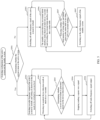
- FIG. 5 is a flowchart of an active-standby switching process according to an alternative embodiment of the present invention. Referring to FIG. 5 , the flowchart may include the following step 501 to step 507.
- Step 501 may include switching on functions of the active system and the standby system, determining whether the current system is the active system 62.
- the current system may be set by the user on the user interface of the user terminal described above.
- Step 502 may include switching on radio frequency signal of the active system 62 by default when a determining result of the above step 501 is yes, and setting an alarm level that needs to be switched to a severe level.
- Step 503 may include detecting an acquired device detection result at intervals as 5 seconds, and determining whether a severe level of alarm is generated based on the device detection result; if not, cyclically executing the above step 502.
- Step 504 may include if a determining result of the above step 503 is yes, stopping sending a square wave signal, switching off radio frequency signal output, and cyclically executing the above step 503 to continue to detect the acquired device detection result.
- Step 505 may include if the determining result of the above step 501 is no, at this moment, the current system being the standby system 66, switching off radio frequency signal of the active system 62 by default.
- Step 506 may include the standby system 66 detecting an external alarm interface status thereof at intervals as 2 seconds and recording the external alarm interface status into a status table.
- Step 507 may include detecting whether the total number of rising edges and falling edges in the status table is less than 20% of a normal number, if no, cyclically executing the above step 505; if yes, switching on the radio frequency signal of the standby system 66, and cyclically executing the above step 506.
- FIG. 6 is a block diagram of an architecture of the active-standby switching processing system according to an embodiment of the present application.
- the system includes an active system 62, a control apparatus 64, and a standby system 66.
- the control apparatus 64 is connected to the active system 62 and the standby system 66, respectively, and the active system 62 is connected to the standby system 66 by an external warning line 68.
- the control device 64 is configured to acquire a device detection result of the active system 62, instruct the active system 62 to send a detection signal to the external warning line 68 according to the device detection result, and execute a switching operation between the active system 62 and the standby system 66 according to the detection signal.
- the external warning line 68 is deployed between the active system 62 and the standby system 66, a detection signal is generated between the active system 62 and the standby system 66 to realize automatic switching between the active system 62 and the standby system 66, and the generated detection signal does not need to take up additional resources, thus enabling rapid switching among multiple communication systems while maintaining communication quality, solving a problem of resource waste and low processing efficiency in the switching process of the active system and the standby system, and realizing automatic switching among multiple communication systems based on software control.
- control apparatus 64 may be further configured to acquire a preset alarm item and a preset alarm level, acquire an alarm flag corresponding to the alarm item in the active system 62 according to the alarm level, and acquire the device detection result according to detection information for the alarm flag in a first preset cycle.
- the detection signal may include a square wave signal
- the control apparatus 64 may be further configured to instruct the active system 62 to send the square wave signal to the external warning line 68 in a case that the device detection result is device normal, instruct the active system to stop sending the square wave signal to the external warning line in a case that the device detection result is device alarm, and execute the switching operation according to a statistical result of the square wave signal in a second preset cycle.
- the active system 62 may include an access unit 621 and at least two first remote units 622, all of the at least two first remote units 622 may be cascaded with each other, and the standby system 66 may include at least two second remote units 661.
- the at least two first remote units 622 may be connected to the at least two second remote units 661 by the external warning line 68, respectively.
- the control apparatus 64 may be further configured to send a switching flag to the at least two first remote units 622 in cascade in turn according to the detection signal in a case that the device detection result is matched with the access unit 621, and all of the at least two first remote units are configured to switch with the at least two second remote units 661 based on the switching flag.
- the control apparatus 64 may be further configured to send the switching flag to at least one alarm remote unit according to the detection signal in a case that the device detection result is matched with the at least one alarm remote unit of the at least two first remote units 622, and the at least one alarm remote unit is configured to switch with a corresponding second remote unit based on the switching flag.
- control apparatus 64 may be further configured to switch the active system 62 to the standby system 66 according to the detection signal, and switch the standby system 66 back to the active system 62 when it is detected that the active system 62 returns to normalcy in a case that the active system 62 is switched to the standby system 66.
- the number of the standby system 66 may be at least two, the control apparatus 64 may be further configured to acquire a preset list of priorities for all of the at least two standby systems 66, acquire a target standby system with the highest priority among the at least two standby systems 66 according to the list of priorities, and execute the switching operation between the active system 62 and the target standby system according to the detection signal.
- control apparatus 64 may be further configured to store the detection signal to a state table deployed in the standby system 66 to obtain a signal state and execute the switching operation according to the signal state.
- a computer device 700 is provided, and the computer device 700 may be a server.
- FIG. 7 is a structural diagram of an interior of a computer device in an embodiment of the present invention.
- the computer device may include a processor 71, a memory and a network interface 73 connected by a system bus.
- the processor 71 of the computer device is configured to provide computing and control capabilities.
- the memory of the computer device may include a storage medium 721 and an internal memory 722.
- the storage medium 721 may store an operating system, computer programs and a database.
- the internal memory 722 may provide an environment for operation of the operating system and computer programs in the storage medium 721.
- the database of the computer device is configured to store the detection signal.
- the network interface 73 of the computer device is configured to communicate with an external terminal by a network connection.
- the computer programs may be executed by the processor 71 to implement an active-standby switching processing method.
- FIG. 7 is only a block diagram of a part of the structure related to the present invention and does not constitute a limitation of the computer device which the present invention is applied to, and a specific computer device may include more or less parts than shown in the figure, or a combination of some parts.
- the specific computer device may have a different component arrangement.
- an electronic apparatus 800 is provided in an embodiment, including a memory 81 and a processor 82.
- the memory 81 stores a computer program
- the processor 82 is configured to execute the computer program to perform steps in any of the above method embodiments.
- the electronic apparatus may further include a transmission device and an input/output device.
- the transmission device may be connected to the processor 82, and the input/output device may be connected to the processor 82.
- the processor 82 may be configured to perform the following step 1 and step 2 by the computer program.
- Step 1 includes acquiring a device detection result of the active system.
- Step 2 includes instructing the active system to send a detection signal to an external warning line according to the device detection result, and executing a switching operation between the active system and the standby system according to the detection signal.
- an embodiment of the present invention may provide a storage medium 721 for implementation.
- a computer program is stored in the storage medium 721, and the computer program is executed by a processor to perform the active-standby switching processing method in any of the above embodiments.
- the computer program may be stored in a non-volatile computer-readable storage medium, the computer program may include processes of the above embodiments when executed.
- Any reference to memory, storage, database or other media used in each embodiment provided in the present invention may include non-volatile and/or volatile memory.
- the non-volatile memory may include a read-only memory (ROM), a programmable ROM (PROM), an electrically programmable ROM (EPROM), an electrically erasable programmable ROM (EEPROM), or a flash memory.
- the volatile memory may include a random-access memory (RAM) or an external cache memory.
- RAM is available in many forms, such as static RAM (SRAM), dynamic RAM (DRAM), synchronous DRAM (SDRAM), dual data rate SDRAM (DDRSDRAM), enhanced SDRAM (ESDRAM), synchronous link DRAM (SLDRAM), Rambus RAM (RDRAM), Direct Rambus Dynamic RAM (DRDRAM), Rambus Dynamic RAM (RDRAM), etc.
- SRAM static RAM
- DRAM dynamic RAM
- SDRAM synchronous DRAM
- DDRSDRAM dual data rate SDRAM
- ESDRAM enhanced SDRAM
- SLDRAM synchronous link DRAM
- RDRAM Rambus RAM
- DRAM Direct Rambus Dynamic RAM
- RDRAM Rambus Dynamic RAM
- modules may be a functional module or a program module, and may be implemented either by software or by hardware.
- the above modules may be located in the same processor, or the above modules may be located in different processors in any combination.
- the present invention may further provide an electronic apparatus, including a processor and a memory that stores a computer program running on the processor, and the computer program may be executed by the processor to implement the steps of the above network traffic anomaly detection method.
Landscapes
- Engineering & Computer Science (AREA)
- Computer Networks & Wireless Communication (AREA)
- Signal Processing (AREA)
- Hardware Redundancy (AREA)
Applications Claiming Priority (2)
| Application Number | Priority Date | Filing Date | Title |
|---|---|---|---|
| CN202110779347.0A CN113645650B (zh) | 2021-07-09 | 2021-07-09 | 主备切换的处理方法、系统、电子装置和存储介质 |
| PCT/CN2022/102719 WO2023280041A1 (fr) | 2021-07-09 | 2022-06-30 | Procédé et système de traitement de commutation de veille active, et appareil électronique et support de stockage |
Publications (2)
| Publication Number | Publication Date |
|---|---|
| EP4351205A1 true EP4351205A1 (fr) | 2024-04-10 |
| EP4351205A4 EP4351205A4 (fr) | 2024-11-13 |
Family
ID=78416980
Family Applications (1)
| Application Number | Title | Priority Date | Filing Date |
|---|---|---|---|
| EP22836794.2A Pending EP4351205A4 (fr) | 2021-07-09 | 2022-06-30 | Procédé et système de traitement de commutation de veille active, et appareil électronique et support de stockage |
Country Status (4)
| Country | Link |
|---|---|
| US (1) | US20240106699A1 (fr) |
| EP (1) | EP4351205A4 (fr) |
| CN (1) | CN113645650B (fr) |
| WO (1) | WO2023280041A1 (fr) |
Families Citing this family (3)
| Publication number | Priority date | Publication date | Assignee | Title |
|---|---|---|---|---|
| CN113645650B (zh) * | 2021-07-09 | 2024-06-04 | 三维通信股份有限公司 | 主备切换的处理方法、系统、电子装置和存储介质 |
| CN114928563B (zh) * | 2022-05-27 | 2025-03-07 | 江苏苏商银行股份有限公司 | 一种分布式渠道自动切换方法及存储介质 |
| WO2025008949A1 (fr) * | 2023-07-03 | 2025-01-09 | Jio Platforms Limited | Procédé et système de commutation d'un processus actif à un processus en veille |
Family Cites Families (25)
| Publication number | Priority date | Publication date | Assignee | Title |
|---|---|---|---|---|
| US7280564B1 (en) * | 1995-02-06 | 2007-10-09 | Adc Telecommunications, Inc. | Synchronization techniques in multipoint-to-point communication using orthgonal frequency division multiplexing |
| CN1251419C (zh) * | 2002-05-30 | 2006-04-12 | 华为技术有限公司 | 通信设备中实现主备设备快速倒换的方法 |
| US20040001449A1 (en) * | 2002-06-28 | 2004-01-01 | Rostron Andy E. | System and method for supporting automatic protection switching between multiple node pairs using common agent architecture |
| CN100493017C (zh) * | 2003-06-25 | 2009-05-27 | 华为技术有限公司 | 一种主备设备自动切换的方法 |
| JP4420275B2 (ja) * | 2003-11-12 | 2010-02-24 | 株式会社日立製作所 | フェイルオーバクラスタシステム及びフェイルオーバクラスタシステムを用いたプログラムのインストール方法 |
| CN101640688B (zh) * | 2009-08-20 | 2014-03-12 | 中兴通讯股份有限公司 | 基于cdn的节点主备用控制器切换方法及cdn网络 |
| CN101697623A (zh) * | 2009-10-22 | 2010-04-21 | 福建三元达通讯股份有限公司 | 射频拉远系统及其近端设备 |
| CN102547806B (zh) * | 2010-12-10 | 2015-08-19 | 中国移动通信集团广东有限公司 | 一种分布式基站系统及其链路保护方法 |
| CN102025551A (zh) * | 2010-12-23 | 2011-04-20 | 中兴通讯股份有限公司 | 基于接入网关的主备用设备切换方法和装置 |
| CN102325340B (zh) * | 2011-07-26 | 2013-12-25 | 京信通信系统(中国)有限公司 | 一种信源小区备份方法及系统 |
| CN102395133A (zh) * | 2011-08-10 | 2012-03-28 | 华为技术有限公司 | 多站点共小区组网方法、基带单元、射频拉远单元及系统 |
| CN103209428B (zh) * | 2012-01-12 | 2018-02-16 | 中兴通讯股份有限公司 | 一种处理射频故障的方法和bbu、bts |
| AU2012387975B2 (en) * | 2012-10-26 | 2016-03-17 | Huawei Technologies Co., Ltd. | PCIE switch-based server system, switching method and device |
| BR112016025286B1 (pt) * | 2015-05-08 | 2023-04-25 | Comba Network Systems Company Limited | Sistema e método para backup de sinal de unidade principal de das ativo |
| CN106301823B (zh) * | 2015-05-19 | 2020-12-18 | 中兴通讯股份有限公司 | 一种关键组件的故障告警方法、装置及大数据管理系统 |
| CN106332151A (zh) * | 2015-06-29 | 2017-01-11 | 中兴通讯股份有限公司 | 射频拉远单元的外场维护方法、装置、终端设备及系统 |
| CN109032235A (zh) * | 2017-06-09 | 2018-12-18 | 许继电气股份有限公司 | 一种高压statcom控保系统及其主备系统的切换方法 |
| CN107688547B (zh) * | 2017-08-23 | 2020-06-16 | 苏州浪潮智能科技有限公司 | 一种控制器主备切换的方法及系统 |
| CN109698775A (zh) * | 2018-11-21 | 2019-04-30 | 中国航空工业集团公司洛阳电光设备研究所 | 一种基于实时状态检测的双机冗余备份系统 |
| CN109768884A (zh) * | 2018-12-26 | 2019-05-17 | 京信通信系统(中国)有限公司 | 通信系统及其高可用性的实现方法、装置和计算机设备 |
| CN109995419B (zh) * | 2019-03-25 | 2021-11-16 | 睿高(广州)通信技术有限公司 | 卫星变频功放系统及其终端备份方法和装置 |
| CN112218321B (zh) * | 2020-10-15 | 2023-10-20 | 京信网络系统股份有限公司 | 主备链路切换方法、装置、通信设备和存储介质 |
| CN112306813B (zh) * | 2020-11-13 | 2023-03-14 | 苏州浪潮智能科技有限公司 | 一种系统告警方法及装置 |
| CN112737844A (zh) * | 2020-12-28 | 2021-04-30 | 浙江中控技术股份有限公司 | 冗余系统中主备切换的方法和装置 |
| CN113645650B (zh) * | 2021-07-09 | 2024-06-04 | 三维通信股份有限公司 | 主备切换的处理方法、系统、电子装置和存储介质 |
-
2021
- 2021-07-09 CN CN202110779347.0A patent/CN113645650B/zh active Active
-
2022
- 2022-06-30 EP EP22836794.2A patent/EP4351205A4/fr active Pending
- 2022-06-30 WO PCT/CN2022/102719 patent/WO2023280041A1/fr not_active Ceased
-
2023
- 2023-12-06 US US18/531,611 patent/US20240106699A1/en active Pending
Also Published As
| Publication number | Publication date |
|---|---|
| WO2023280041A1 (fr) | 2023-01-12 |
| US20240106699A1 (en) | 2024-03-28 |
| EP4351205A4 (fr) | 2024-11-13 |
| CN113645650A (zh) | 2021-11-12 |
| CN113645650B (zh) | 2024-06-04 |
Similar Documents
| Publication | Publication Date | Title |
|---|---|---|
| US20240106699A1 (en) | Active-standby switching processing method and system, and electronic apparatus and storage medium | |
| US12028811B2 (en) | Method and apparatus for controlling power consumption of terminal, and storage medium | |
| EP3171616A1 (fr) | Procédé et appareil de commande de connexion bluetooth pour de multiples dispositifs de lecture et système de lecture de musique | |
| CN107846672A (zh) | 多模IoT设备的通信模式选择方法、IoT设备及存储介质 | |
| CN108429576B (zh) | 无人机通信方法、控制终端及无人机控制系统 | |
| EP3841655B1 (fr) | Alimentation sur ethernet intégrée avec ou dans un système de sécurité des installations | |
| EP3537847B1 (fr) | Procédé et dispositif de gestion de coupure de courant et d'acquisition de relations de connexion | |
| JP6708318B1 (ja) | 蓄電池監視装置及び蓄電池監視方法 | |
| US20190227895A1 (en) | Information processing device, status monitoring system, and recording medium | |
| CN112367499B (zh) | 一种远程监控电力设备的服务端及监控端电力数据处理方法 | |
| EP2775740B1 (fr) | Système de réseau, groupe de dispositifs formant noeuds, groupe de dispositifs formant capteurs et procédé pour la transmission et la réception de données de détection | |
| EP3082376B1 (fr) | Procédé de découverte de dispositif de réseau et système de découverte de dispositif de réseau | |
| US11356230B2 (en) | Channel transmission methods and device | |
| US20200137831A1 (en) | Frequency band authentication method and apparatus for wireless device, and computing device | |
| US11825411B2 (en) | Network device, method and computer readable medium for wireless networks | |
| EP3742414A1 (fr) | Dispositif de communication d'informations détectées, système de communication d'informations détectées, système de communication, procédé de radiocommunication et programme | |
| US9542580B2 (en) | RFID communication system and method for controlling same | |
| CN110096409A (zh) | 异常报警方法、装置、监控装置及计算机可读存储介质 | |
| CN110119111B (zh) | 通信方法及装置、存储介质、电子装置 | |
| JP6249471B2 (ja) | 情報収録システム、収録システム用障害対処方法、及びその障害対処プログラム | |
| CN117395615B (zh) | 车辆系统中蓝牙稳定广播的装置和方法 | |
| KR102916066B1 (ko) | 스마트 멀티탭을 포함하는 스마트 IoT 시스템 | |
| CN114830613A (zh) | 一种通信传输的方法、设备及系统 | |
| WO2026067413A1 (fr) | Procédé de communication et appareil de communication | |
| WO2024125440A1 (fr) | Procédé d'annulation de commutation de paquets, terminal et dispositif côté réseau |
Legal Events
| Date | Code | Title | Description |
|---|---|---|---|
| STAA | Information on the status of an ep patent application or granted ep patent |
Free format text: STATUS: THE INTERNATIONAL PUBLICATION HAS BEEN MADE |
|
| PUAI | Public reference made under article 153(3) epc to a published international application that has entered the european phase |
Free format text: ORIGINAL CODE: 0009012 |
|
| STAA | Information on the status of an ep patent application or granted ep patent |
Free format text: STATUS: REQUEST FOR EXAMINATION WAS MADE |
|
| 17P | Request for examination filed |
Effective date: 20231214 |
|
| AK | Designated contracting states |
Kind code of ref document: A1 Designated state(s): AL AT BE BG CH CY CZ DE DK EE ES FI FR GB GR HR HU IE IS IT LI LT LU LV MC MK MT NL NO PL PT RO RS SE SI SK SM TR |
|
| REG | Reference to a national code |
Ref country code: DE Ref legal event code: R079 Free format text: PREVIOUS MAIN CLASS: H04W0024040000 Ipc: H04L0041066300 |
|
| DAV | Request for validation of the european patent (deleted) | ||
| DAX | Request for extension of the european patent (deleted) | ||
| A4 | Supplementary search report drawn up and despatched |
Effective date: 20241010 |
|
| RIC1 | Information provided on ipc code assigned before grant |
Ipc: H04L 41/0663 20220101AFI20241004BHEP |