EP4351503B1 - Unité dentaire comprenant un écran tactile et un support - Google Patents
Unité dentaire comprenant un écran tactile et un support Download PDFInfo
- Publication number
- EP4351503B1 EP4351503B1 EP22729727.2A EP22729727A EP4351503B1 EP 4351503 B1 EP4351503 B1 EP 4351503B1 EP 22729727 A EP22729727 A EP 22729727A EP 4351503 B1 EP4351503 B1 EP 4351503B1
- Authority
- EP
- European Patent Office
- Prior art keywords
- touch screen
- display unit
- orientation
- dental
- support
- Prior art date
- Legal status (The legal status is an assumption and is not a legal conclusion. Google has not performed a legal analysis and makes no representation as to the accuracy of the status listed.)
- Active
Links
Images


Classifications
-
- A—HUMAN NECESSITIES
- A61—MEDICAL OR VETERINARY SCIENCE; HYGIENE
- A61G—TRANSPORT, PERSONAL CONVEYANCES, OR ACCOMMODATION SPECIALLY ADAPTED FOR PATIENTS OR DISABLED PERSONS; OPERATING TABLES OR CHAIRS; CHAIRS FOR DENTISTRY; FUNERAL DEVICES
- A61G15/00—Operating chairs; Dental chairs; Accessories specially adapted therefor, e.g. work stands
- A61G15/10—Parts, details or accessories
-
- F—MECHANICAL ENGINEERING; LIGHTING; HEATING; WEAPONS; BLASTING
- F16—ENGINEERING ELEMENTS AND UNITS; GENERAL MEASURES FOR PRODUCING AND MAINTAINING EFFECTIVE FUNCTIONING OF MACHINES OR INSTALLATIONS; THERMAL INSULATION IN GENERAL
- F16M—FRAMES, CASINGS OR BEDS OF ENGINES, MACHINES OR APPARATUS, NOT SPECIFIC TO ENGINES, MACHINES OR APPARATUS PROVIDED FOR ELSEWHERE; STANDS; SUPPORTS
- F16M11/00—Stands or trestles as supports for apparatus or articles placed thereon ; Stands for scientific apparatus such as gravitational force meters
- F16M11/02—Heads
- F16M11/04—Means for attachment of apparatus; Means allowing adjustment of the apparatus relatively to the stand
- F16M11/06—Means for attachment of apparatus; Means allowing adjustment of the apparatus relatively to the stand allowing pivoting
- F16M11/10—Means for attachment of apparatus; Means allowing adjustment of the apparatus relatively to the stand allowing pivoting around a horizontal axis
-
- F—MECHANICAL ENGINEERING; LIGHTING; HEATING; WEAPONS; BLASTING
- F16—ENGINEERING ELEMENTS AND UNITS; GENERAL MEASURES FOR PRODUCING AND MAINTAINING EFFECTIVE FUNCTIONING OF MACHINES OR INSTALLATIONS; THERMAL INSULATION IN GENERAL
- F16M—FRAMES, CASINGS OR BEDS OF ENGINES, MACHINES OR APPARATUS, NOT SPECIFIC TO ENGINES, MACHINES OR APPARATUS PROVIDED FOR ELSEWHERE; STANDS; SUPPORTS
- F16M11/00—Stands or trestles as supports for apparatus or articles placed thereon ; Stands for scientific apparatus such as gravitational force meters
- F16M11/20—Undercarriages with or without wheels
- F16M11/2007—Undercarriages with or without wheels comprising means allowing pivoting adjustment
- F16M11/2021—Undercarriages with or without wheels comprising means allowing pivoting adjustment around a horizontal axis
-
- A—HUMAN NECESSITIES
- A61—MEDICAL OR VETERINARY SCIENCE; HYGIENE
- A61G—TRANSPORT, PERSONAL CONVEYANCES, OR ACCOMMODATION SPECIALLY ADAPTED FOR PATIENTS OR DISABLED PERSONS; OPERATING TABLES OR CHAIRS; CHAIRS FOR DENTISTRY; FUNERAL DEVICES
- A61G2203/00—General characteristics of devices
- A61G2203/10—General characteristics of devices characterised by specific control means, e.g. for adjustment or steering
- A61G2203/16—Touchpads
-
- A—HUMAN NECESSITIES
- A61—MEDICAL OR VETERINARY SCIENCE; HYGIENE
- A61G—TRANSPORT, PERSONAL CONVEYANCES, OR ACCOMMODATION SPECIALLY ADAPTED FOR PATIENTS OR DISABLED PERSONS; OPERATING TABLES OR CHAIRS; CHAIRS FOR DENTISTRY; FUNERAL DEVICES
- A61G2203/00—General characteristics of devices
- A61G2203/10—General characteristics of devices characterised by specific control means, e.g. for adjustment or steering
- A61G2203/20—Displays or monitors
-
- F—MECHANICAL ENGINEERING; LIGHTING; HEATING; WEAPONS; BLASTING
- F16—ENGINEERING ELEMENTS AND UNITS; GENERAL MEASURES FOR PRODUCING AND MAINTAINING EFFECTIVE FUNCTIONING OF MACHINES OR INSTALLATIONS; THERMAL INSULATION IN GENERAL
- F16M—FRAMES, CASINGS OR BEDS OF ENGINES, MACHINES OR APPARATUS, NOT SPECIFIC TO ENGINES, MACHINES OR APPARATUS PROVIDED FOR ELSEWHERE; STANDS; SUPPORTS
- F16M2200/00—Details of stands or supports
- F16M2200/02—Locking means
- F16M2200/021—Locking means for rotational movement
Definitions
- the present invention relates to a dental unit comprising a display unit with a touch screen and a support.
- Dental units comprising a display unit with or without a touch screen are well known in the art. It is also well known in the art that dental units comprise features such as an instrument bridge with a plurality of dental instruments, such as dental drills, suction devices and flushing devices, a chair adapted for accommodating a patient during treatment and means separate from the dental instruments on the instrument bridge for providing water and/or suction. It is also well known in the art of dental units that the instrument bridge and the display unit may be arranged on a suitable holder such as to provide a flexible working environment for the dental care professional.
- Dental examinations and dental treatments are operations requiring dental care professionals to switch between on the one hand checking information on a screen and/or displaying information to the dental care professional, or possibly even to the patient, and on the other hand entering into a computer system new information and/or changes to settings, e.g. of various dental instruments.
- dental units are generally complex structures which comprise many different components including displays, instrument bridges and instruments and a chair, the cleaning and sterilization procedure is time consuming.
- Cleaning the touch screen of the display unit may at least in some positions thereof be difficult. Also, the positioning of the display unit may further force the cleaner to make unergonomic movements and/or to take up unergonomic positions to clean the touch screen. Also, cleaning the touch screen of the display unit involves a risk of involuntarily causing inputs to the touch screen, which may in turn interfere with chosen and other settings.
- EP 1 010 404 A2 discloses a dental unit with a chair, touch screens and a display.
- the touch screen is connected to a supply unit.
- the supply unit comprises a computer to which all units of the system is connected. None of the touch screens and th display are rotatable.
- JP 2011 161113 A discloses a dental unit with a chair, a computer with a touch screen and a display and an instrument bridge with various dental instruments.
- the touch screen may be operated in either of a touch operation mode and a display mode.
- a changeover switch may be set to ON so that a touch operation on the touch screen is possible, or to OFF so that the touch screen does not accept a touch operation.
- the touchscreen is not rotatable.
- US 2004/178312 A1 discloses a display which may be positioned above a dental chair. The position of the display may be adjusted about swivel and pivot axes.
- the display screen may comprise a touchscreen, thus allowing for input to be given to the display through the touch screen.
- DE 102010021885 A1 discloses a dental chair with a touch screen which is arranged behind a glass plate.
- the glass plate is preprogrammed in such a way that functionalities may be activated when touching one of four preprogrammed positions.
- a service button is provided with which the touch screen and glass plate may be turned off completely for the purpose of cleaning the glass plate.
- the glass plate is resistant to liquids, particularly disinfectants.
- JP 2004 195092 A discloses a touch screen for controlling the posture is turned around the tray table of the chair unit for dentistry, and the touch screen itself can be rotated and inclined forward/backward and left/right. Further, the tray table has a mechanism to lock the tray table in any set posture.
- a dental unit comprising a support and a display unit with a touch screen, the display unit being connected to the support in such a manner that the display unit is rotatable between a first orientation and a second orientation, the first orientation being suitable for enabling a dental care professional to view content displayed on the touch screen during work on a patient situated in a chair of the dental unit, and is thus for displaying content on the touch screen, and the second orientation being suitable for enabling a dental care professional to input information by touching the touch screen and is thus for receiving input by means of the touch screen, and the support being adapted to support the display unit in the second orientation.
- a dental unit is provided with which both entering information on the touch screen and viewing content on the display unit during work on a patient is easy, and which dental unit is thus easier to operate and furthermore provides a more ergonomically correct work environment for dental care professionals.
- a dental unit is provided with which entering information on the touch screen is easy when the display unit is in the second orientation and with which and viewing content on the display unit is easy when the display unit is in the first orientation.
- Such a dental unit is also easier to operate and provides a more ergonomically correct work environment for dental care professionals.
- the support is adapted to support the display unit in the second orientation
- a dental unit is provided with which the display unit is stabilized in the second orientation, thus providing improved conditions for entering information on the touch screen.
- the second orientation is horizontal or arranged in an acute angle with respect to a horizontal plane.
- the second orientation is extending in an angle ⁇ with respect to a horizontal plane, the angle ⁇ being between 0 and 40 degrees, between 0 and 15 degrees, or between 0 and 10 degrees.
- the support comprises a first section and a second section, the first section extending in an angle ⁇ with the second section, the angle ⁇ being in the interval of 60-120 degrees, in the interval of 75-105 degrees, in the interval of 80-100 degrees or in the interval of 85-95 degrees.
- the angle ⁇ is 90 degrees.
- the support comprises a first section adapted to support at least 5 %, 10%, or 15% of the area of a rear surface of the display unit in the second orientation.
- the support and the display unit are connected by means of a pivot connection or a hinged connection.
- a dental unit is provided with which the abovementioned rotata-bility of the display unit between the first orientation and the second orientation is obtained in a particularly simple manner, both from a practical and a constructional point of view.
- the support is configured to act as a stop for the display unit when the display unit reaches the second orientation.
- a dental unit is provided with which it is ensured that the display unit may not be moved or rotated beyond the second orientation, and thus that when the dental care professional rotates the display unit towards the second orientation, the display unit is brought into the second orientation in a particularly simple manner.
- the support comprises an abutment surface adapted for abutting a rear surface of the display unit in the second orientation.
- a dental unit is provided with which the stability of the display unit in the second orientation is particularly good, thus providing further improved conditions for entering information on the touch screen.
- the abutment surface has a shape matching the shape of the rear surface of the display unit.
- the abutment surface will be a planar surface
- the abutment surface will be convex
- the abutment surface will be concave.
- the abutment surface is a planar surface, and the rear surface of the display unit is planar.
- the rear surface of the display unit has a width and a height, wherein the abutment surface supports the rear surface of the display along at least 30% of its height.
- the first orientation is vertical or arranged in an acute angle ⁇ with respect to a vertical plane.
- the angle ⁇ may be within 30 degrees, within 20 degrees or within 10 degrees with respect to the vertical plane or within 5 degrees with respect to the vertical plane.
- the angle ⁇ may for instance be 0 degrees with respect to the vertical plane, and thus perpendicular to the horizontal plane.
- the touch screen is configured to, when placed in the second orientation, display a keyboard.
- the display unit may comprise a data processing device configured to, when detecting that the touch screen placed in the second orientation, present on the touch screen a keyboard, or alternatively present on the touch screen a virtual button which, when pressed by a user, triggers the display of a keyboard on the touch screen.
- the touch screen may be locked.
- the touch screen of the display unit may particularly be adapted to be locked in such a way that the touch screen when touched does not react or registers touches.
- a dental unit is thereby provided with which cleaning of the touch screen is easy and does not cause activation of the touch screen, and which furthermore provides a more ergonomically correct work environment for not only dental care professionals but also cleaning personnel while cleaning the display unit.
- the touch screen of the display unit is adapted to be locked when the display unit and touch screen is in at least one of the first and the second orientation.
- a dental unit with a particularly good ergonomically correct work environment for not only dental care professionals but also cleaning personnel while cleaning the display unit is provided for.
- the touch screen of the display unit is adapted to be locked when the display unit and touch screen is in at least one intermediate orientation between the first and the second orientation.
- a dental unit which, in addition to the abovementioned advantages, also provide the possibility of enabling both dental care professionals and cleaning personnel to rotate the display unit, e.g. between the first and second orientation, or clean the display unit in an intermediate position, without inadvertently causing unwanted activation of the touch screen.
- the touch screen of the display unit is adapted to be unlocked subsequently to being locked.
- the dental unit further comprises an external actuator adapted to allow unlocking and/or locking of the touch screen of the display unit.
- a dental unit is provided with which unlocking of the touch screen after cleaning becomes possible without contaminating the touch screen.
- the external actuator may be any one of a foot pedal, a button, a lever and a remote control.
- a dental unit is provided with which the advantages of unlocking of the touch screen after cleaning without contaminating the touch screen is obtained in a particularly simple manner, both from a practical and a constructional point of view.
- the external actuator is not physically connected to the display unit.
- a dental unit is provided with which the risk of contaminating the touch screen when unlocking the touch screen after cleaning is minimized or eliminated altogether.
- the external actuator is connected to the display unit by means of a wireless connection.
- a dental unit is provided with which the risk of contaminating the touch screen when unlocking of the touch screen after cleaning is minimized or eliminated altogether in a particularly simple manner, both from a practical and a constructional point of view.
- Fig. 1 shows a dental unit 1 according to an embodiment of the invention.
- the dental unit 1 comprises a display unit 2 and a support 3.
- the display unit 2 comprises a touch screen 21.
- the touch screen 21 generally extends in a touch screen plane P.
- the touch screen 21 is provided in order to enable both displaying information or content and inputting information.
- the information or content to be displayed may be both directed to the dental care professional or to the patient.
- Information directed to the dental care professional may e.g. relate to dental instruments or to the patient.
- Information or content directed to the patient may e.g. be illustrations to accompany information given by the dental care professional or it may be entertainment.
- Information to be inputted may for instance be desired settings relating to dental instruments 41 or information to be entered into the patient's record.
- the display unit 2 may further comprise a handle 22 for manually moving the display unit 2 and touch screen 21.
- the dental unit 1 may further comprise an instrument bridge 4 with a plurality of dental instruments 41.
- the instrument bridge 4 may be arranged on a holder 42.
- the dental unit 1 may further comprise a chair 11 adapted for accommodating a patient during treatment. Means 10 for providing water and/or suction may also be provided.
- the dental unit 1 may further comprise a foot pedal 12 adapted for performing certain functions in relation to the dental unit, such as e.g. operating the chair 11.
- the display unit 2 and thus the touch screen 21, is rotatable between a first orientation ( Figs. 1 and 2 ) and a second orientation ( Fig. 3 ).
- the first orientation is adapted for displaying content on the touch screen 21.
- the first orientation is chosen or configured such that the first orientation is suitable for enabling a dental care professional to view content displayed on the touch screen 21 while working on a patient.
- the first orientation is vertical or arranged in an acute angle ⁇ with respect to the vertical plane V.
- the first orientation is provided to extend in an angle ⁇ of within +/ 10 degrees with respect to the vertical plane V or within +/ 5 degrees with respect to the vertical plane V.
- the angle ⁇ may for instance be 0 degrees with respect to the vertical plane V, and thus perpendicular to the horizontal plane H.
- the touch screen plane P in which the touch screen 21 extends, is arranged vertical or arranged in the said acute angle ⁇ with respect to the vertical plane V.
- the second orientation is adapted for receiving input by means of the touch screen 21.
- the second orientation is chosen or configured such that the second orientation is suitable for enabling a dental care professional to input information by touching the touch screen 21 while providing a comfortable and ergonomically acceptable working position.
- the second orientation is provided to extend in an angle ⁇ of within +/ 10 degrees with respect to the horizontal plane H or within +/ 5 degrees with respect to the horizontal plane H.
- the angle ⁇ may for instance be 0 degrees with respect to the horizontal plane H, and thus perpendicular to the vertical plane V.
- the touch screen plane P in which the touch screen 21 extends, is arranged horizontal or is arranged in the said angle ⁇ with respect to the horizontal plane H.
- both planes H and V extend perpendicular to the plane of the paper.
- the touch screen 21 may further be configured to, when placed in the second orientation, display a keyboard.
- the display unit 2 may comprise a data processing device configured to detect the orientation of the display unit 2 and/or the touch screen 21 and to, when detecting that the touch screen 21 is placed in the second orientation, present on the touch screen 21 a keyboard or alternatively a virtual button which, when pressed by a user, triggers the display of a keyboard on the touch screen 21.
- the touch screen 21 may also be configured to, when placed in any other orientation than the second orientation, not display a keyboard.
- the support 3 is adapted to support the display unit 2 and thus the touch screen 21 in the second orientation - see Fig. 3 .
- the support 3 comprises a first section 31 and a second section 32.
- the first section 31 is connected, or is adapted to be connected, to the display unit 2.
- the first section 31 is furthermore adapted to support a part, particularly at least 5 %, of the area of a rear surface 24 of the display unit 2 in the second orientation.
- the second section 32 is connected, or is adapted to be connected, to a holding device 9 (cf. Fig. 2 ) or an arm 6 connected to a holding device 9.
- the first section 31 is arranged such as to extend, in an assembled condition of the dental unit 1, in an angle ⁇ with respect to the horizontal.
- the angle ⁇ may be within +/ 20 degrees with respect to the horizontal, or within +/ 5 degrees with respect to the horizontal.
- the first section 31 may further comprise an abutment surface 36.
- the abutment surface 36 is adapted for abutting a rear surface 24 of the display unit 2 in the second orientation of the display unit, thereby providing improved support of the display unit 2.
- the abutment surface 36 may be adapted to support at least 5 % of the area of the rear surface 24 of the display unit 2 in the second orientation.
- the abutment surface 36 may be shaped such as to conform to the shape of the rear surface 24 of the display unit 2 such as to provide for an improved support of the display unit 2 in the second orientation.
- the abutment surface 36 may be a plane surface, and the rear surface 24 of the display unit 2, or at least a part of the rear surface 24, may be a corresponding plane surface.
- the display unit 2 and the support 3 are connected pivotally to one another.
- the connection between the display unit 2 and the support 3 is provided as a hinged or pivotal connection.
- the display unit comprises a connecting section 23 and the support 3 comprises a corresponding connecting section 33.
- the first section 31 of the support 3 comprises the connecting section 33.
- the connecting sections 23 and 33 are connected to one another by means of a pivot axis 7 such that the display unit 2 may pivot around the pivot axis 7.
- the first section 31 and the second section 32 are connected in a bend 35 and extend in an angle ⁇ with one another.
- the angle ⁇ lies in the interval of 60-120 degrees, the interval of 80-100 degrees or in the interval of 85-95 degrees.
- the angle ⁇ may for instance be 90 degrees.
- the first section 31 and the second section 32 may be made in one piece, e.g. by casting or moulding, or may be welded together.
- the second section 32 is connected to an arm 6 by means of a connection.
- the connection between the second section 32 of the support 3 and the arm 6 may be provided as a hinged or pivotal connection such as to enable a further degree of freedom in adjustment of the orientation of the display 2 and touch screen 21.
- the support 3 comprises a connecting section 34 provided on the second section 32
- the arm 6 comprises a corresponding connecting section 61.
- the connecting sections 34 and 61 are connected to one another by means of a pivot axis 8 such that the support 3 and thereby the display unit 2 may pivot around the pivot axis 8.
- the connecting section 34 and the second section 32 may also be connected pivotally to one another. Thereby, a still further degree of freedom in adjustment of the orientation of the display 2 and touch screen 21.
- the second section 32 is rotatable with respect to the connecting section 34 around an axis extending in the longitudinal direction of the second section 32 and/or the connecting section 34.
- the arm 6 may be omitted and the second section 32 of the support 3 may be connected directly and pivotally to the holding means 9.
- the connecting section 61 may be provided on the holding means 9.
- Figs. 1 and 2 show the display unit 2, and thus the touch screen 21, arranged in the first orientation.
- the display unit 2, and thus the touch screen 21, and the first section 31 of the support 3 are in the first orientation arranged perpendicular or substantially perpendicular to one another.
- the display unit 2, and thus the touch screen 21, is arranged in a vertical orientation, or in an angle with respect to the vertical corresponding in size to the angle ⁇ described above.
- the first orientation is adapted for displaying content on the touch screen 21.
- Fig. 3 shows the display unit 2, and thus the touch screen 21, arranged in the second orientation.
- the display unit 2, and thus the touch screen 21, is in the second orientation arranged resting on or in abutment with the first section 31 of the support 3.
- the display unit 2, and thus the touch screen 21, is arranged in a horizontal orientation, or in an angle with respect to the horizontal H corresponding in size to the angle ⁇ described above.
- the support 3 ensures a stable positioning of the display unit 2, and thus the touch screen 21.
- the second orientation is adapted for inputting information on the touch screen 21.
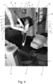
- a dental unit 20 according to another embodiment of the invention is shown.
- the dental unit 20 shown in Fig. 4 differs from that described above with reference to Figs. 13 in that the touch screen 21 of the display unit 20 is adapted to be locked in such a way that the touch screen does not react when touched or registers touches.
- the touch screen 21 may be adapted to be locked when the display unit 20 and touch screen 21 is in one or more of the first orientation, the second orientation and at least one intermediate orientation between the first and the second orientation.
- the touch screen 21 of the display unit 20 is adapted to be unlocked subsequently to being locked.
- the dental unit 20 may further comprise an external actuator 13 to allow unlocking and/or locking of the touch screen 21 of the display unit 2.
- the external actuator 13 is not connected physically, but rather by means of a wireless connection, to the display unit 2.
- the external actuator 13 may be a foot pedal as shown in Fig. 4 .
- the external actuator 13 may be a button or a lever or a remote control.
- At least locking of the touch screen 21 of the display unit 2 may also be achieved by operating an actuator provided digitally on the touch screen 21 or being physically connected to the touch screen 21 or the display unit 2.
Landscapes
- Health & Medical Sciences (AREA)
- General Engineering & Computer Science (AREA)
- Engineering & Computer Science (AREA)
- Veterinary Medicine (AREA)
- General Health & Medical Sciences (AREA)
- Public Health (AREA)
- Animal Behavior & Ethology (AREA)
- Life Sciences & Earth Sciences (AREA)
- Oral & Maxillofacial Surgery (AREA)
- Mechanical Engineering (AREA)
- Dental Tools And Instruments Or Auxiliary Dental Instruments (AREA)
- Devices For Indicating Variable Information By Combining Individual Elements (AREA)
- Accommodation For Nursing Or Treatment Tables (AREA)
Claims (15)
- Unité dentaire (1), comprenant un support (3) et une unité d'affichage (2) munie d'un écran tactile (21),l'unité d'affichage (2) étant reliée au support (3) de sorte que l'unité d'affichage (2) est rotative entre une première orientation et une deuxième orientation,la première orientation étant apte à permettre à un professionnel des soins dentaires de visualiser un contenu affiché sur l'écran tactile (21) au cours d'une intervention sur un patient situé sur un fauteuil de l'unité dentaire (1), et servant ainsi à afficher un contenu sur l'écran tactile (21),la deuxième orientation étant apte à permettre à un professionnel des soins dentaires d'entrer des informations en touchant l'écran tactile (21), et servant ainsi recevoir une entrée au moyen de l'écran tactile, etle support étant adapté à supporter l'unité d'affichage (2) dans la deuxième orientation, etla deuxième orientation étant horizontale ou agencée de manière à former un angle aigu avec un plan horizontal, le support (3) comprenant une surface de butée (36),la surface de butée (36) étant adaptée à venir buter contre une surface arrière (24) de l'unité d'affichage (2) dans la deuxième orientation.
- Unité dentaire selon la revendication 1, dans laquelle la deuxième orientation s'étend en formant un angle α avec un plan horizontal, l'angle α étant compris entre 0 et 40 degrés, entre 0 et 15 degrés, ou entre 0 et 10 degrés.
- Unité dentaire selon l'une quelconque des revendications précédentes, dans laquelle le support comprend un première partie et une deuxième partie, la première partie s'étendant en formant un angle β avec la première partie, l'angle β s'inscrivant dans l'intervalle allant de 60 à 120 degrés, dans l'intervalle allant de 75 à 105 degrés, dans l'intervalle allant de 80 à 100 degrés, et/ou dans laquelle
le support comprend une première partie, la première partie étant configurée pour supporter au moins 5 % de l'étendue d'une surface arrière de l'unité d'affichage dans la deuxième orientation. - Unité dentaire selon l'une quelconque des revendications précédentes, dans laquelle le support et l'unité d'affichage sont reliés au moyen d'une liaison pivot ou d'une liaison articulée.
- Unité dentaire selon l'une quelconque des revendications précédentes, dans laquelle le support est configuré pour jouer le rôle de butoir pour l'unité d'affichage lorsque l'unité d'affichage atteint la deuxième orientation.
- Unité dentaire selon l'une quelconque des revendications précédentes, dans laquelle
la surface de butée est une surface plane. - Unité dentaire selon l'une quelconque des revendications précédentes, dans laquelle le support comprend une surface de butée, la surface de butée étant adaptée à supporter au moins 30 % de l'étendue d'une surface arrière de l'unité d'affichage dans la deuxième orientation.
- Unité dentaire selon l'une quelconque des revendications précédentes, dans laquelle la première orientation est verticale ou agencée de manière à former un angle aigu avec un plan vertical.
- Unité dentaire selon l'une quelconque des revendications précédentes, dans laquellel'écran tactile est configuré pour, lorsqu'il est placé dans la deuxième orientation, afficher un clavier, et/ou dans laquellel'unité d'affichage comprend un dispositif de traitement de données configuré pour, lorsqu'il détecte que l'écran tactile est placé dans la deuxième orientation, présenter un clavier sur l'écran tactile, et/ou dans laquellel'unité d'affichage comprend un dispositif de traitement de données configuré pour, lorsqu'il détecte que l'écran tactile est placé dans la deuxième orientation, présenter sur l'écran tactile un bouton virtuel qui, lorsqu'un utilisateur appuie dessus, déclenche l'affichage d'un clavier sur l'écran tactile.
- Unité dentaire selon l'une quelconque des revendications précédentes, dans laquelle l'écran tactile de l'unité d'affichage étant adapté à être verrouillé de telle manière que l'écran tactile, lorsqu'il est touché, ne réagisse pas ou n'enregistre pas de toucher.
- Unité dentaire selon la revendication 10, dans laquelle l'écran tactile de l'unité d'affichage est adapté à être verrouillé lorsque l'unité d'affichage et l'écran tactile occupent au moins une des première et deuxième orientations.
- Unité dentaire selon l'une quelconque des revendications 10 à 11, dans laquelle l'écran tactile de l'unité d'affichage est adapté à être déverrouillé après avoir été verrouillé.
- Unité dentaire selon l'une quelconque des revendications 10 à 12, et comprenant en outre un actionneur externe pour permettre le déverrouillage et/ou le verrouillage de l'écran tactile de l'unité d'affichage.
- Unité dentaire selon la revendication 13, dans laquelle l'actionneur externe est un élément quelconque parmi une pédale, un bouton, un levier et une télécommande.
- Unité dentaire selon la revendication 13 ou 14, dans laquellel'actionneur externe n'est pas physiquement relié à l'unité d'affichage, et/ou dans laquellel'actionneur externe est relié à l'unité d'affichage au moyen d'une liaison sans fil.
Applications Claiming Priority (2)
| Application Number | Priority Date | Filing Date | Title |
|---|---|---|---|
| EP21179142.1A EP4101434A1 (fr) | 2021-06-11 | 2021-06-11 | Unité dentaire comprenant un écran tactile et un support |
| PCT/EP2022/064009 WO2022258360A1 (fr) | 2021-06-11 | 2022-05-24 | Unité dentaire comprenant un écran tactile et un support |
Publications (3)
| Publication Number | Publication Date |
|---|---|
| EP4351503A1 EP4351503A1 (fr) | 2024-04-17 |
| EP4351503C0 EP4351503C0 (fr) | 2025-06-25 |
| EP4351503B1 true EP4351503B1 (fr) | 2025-06-25 |
Family
ID=76444264
Family Applications (2)
| Application Number | Title | Priority Date | Filing Date |
|---|---|---|---|
| EP21179142.1A Withdrawn EP4101434A1 (fr) | 2021-06-11 | 2021-06-11 | Unité dentaire comprenant un écran tactile et un support |
| EP22729727.2A Active EP4351503B1 (fr) | 2021-06-11 | 2022-05-24 | Unité dentaire comprenant un écran tactile et un support |
Family Applications Before (1)
| Application Number | Title | Priority Date | Filing Date |
|---|---|---|---|
| EP21179142.1A Withdrawn EP4101434A1 (fr) | 2021-06-11 | 2021-06-11 | Unité dentaire comprenant un écran tactile et un support |
Country Status (5)
| Country | Link |
|---|---|
| US (1) | US12178762B2 (fr) |
| EP (2) | EP4101434A1 (fr) |
| JP (1) | JP2024520852A (fr) |
| CN (1) | CN117715608A (fr) |
| WO (1) | WO2022258360A1 (fr) |
Family Cites Families (18)
| Publication number | Priority date | Publication date | Assignee | Title |
|---|---|---|---|---|
| US5732712A (en) | 1996-07-12 | 1998-03-31 | Adair; Edwin L. | Sterile encapsulated operating room video monitor and video monitor support device |
| DE19857613A1 (de) * | 1998-12-14 | 2000-06-15 | Christof Ellerbrock | Intelligente medizinische Behandlungsvorrichtung |
| JP2001252313A (ja) * | 2000-03-08 | 2001-09-18 | Osada Res Inst Ltd | 歯科用表示装置搭載支持装置 |
| EP2302541B1 (fr) * | 2001-08-03 | 2016-09-28 | Hill-Rom Services, Inc. | Système informatique de point d'intervention de patient |
| US7347492B2 (en) | 2002-07-10 | 2008-03-25 | Dire Mark L | Chair-side multimedia communication system |
| JP4206748B2 (ja) * | 2002-12-20 | 2009-01-14 | 株式会社モリタ東京製作所 | 歯科用チェアユニットのトレーテーブル |
| US7410138B2 (en) | 2003-03-14 | 2008-08-12 | Tgr Intellectual Properties, Llc | Display adjustably positionable about swivel and pivot axes |
| DE102007050060B4 (de) * | 2007-10-19 | 2017-07-27 | Drägerwerk AG & Co. KGaA | Vorrichtung und Verfahren zur Ausgabe medizinischer Daten |
| KR101055530B1 (ko) | 2008-03-28 | 2011-08-08 | 삼성메디슨 주식회사 | 터치스크린 일체형 디스플레이부를 포함하는 초음파 시스템 |
| JP5162059B2 (ja) * | 2010-02-13 | 2013-03-13 | 株式会社モリタ製作所 | 医療用診療装置 |
| DE102010021885A1 (de) | 2010-05-28 | 2011-12-01 | TGA Technischer Geräte- und Apparatebau GmbH | Vorrichtung der Dentaltechnik mit abgedeckten elektrischen Schaltelementen |
| US20120084728A1 (en) * | 2010-10-05 | 2012-04-05 | Wen-Liang Huang | Button control system for medical touch screen and method thereof |
| CN103793166A (zh) * | 2012-11-05 | 2014-05-14 | 阿里巴巴集团控股有限公司 | 旋转显示内容的方法及终端 |
| US10216228B2 (en) * | 2014-09-15 | 2019-02-26 | Lenovo (Beijing) Co., Ltd. | Multiple display device having a display on a rotary shaft |
| EP3043244B1 (fr) | 2015-01-12 | 2019-09-25 | Mesut Ceyhan | Dispositif avec un écran tactile autostérilisant |
| BR102015023851A2 (pt) * | 2015-09-16 | 2017-03-14 | Pagano Bringel Raquel | braço para cadeira odontológica com dispositivo mouse touch para uso do paciente |
| JP6091677B2 (ja) * | 2016-03-15 | 2017-03-08 | キヤノン株式会社 | 表示制御装置、表示制御装置の制御方法、プログラム、記録媒体 |
| CN108938303A (zh) * | 2017-05-24 | 2018-12-07 | 上海立珂医疗器械有限公司 | 牙科手术座椅 |
-
2021
- 2021-06-11 EP EP21179142.1A patent/EP4101434A1/fr not_active Withdrawn
-
2022
- 2022-05-24 JP JP2023576181A patent/JP2024520852A/ja active Pending
- 2022-05-24 WO PCT/EP2022/064009 patent/WO2022258360A1/fr not_active Ceased
- 2022-05-24 US US18/568,731 patent/US12178762B2/en active Active
- 2022-05-24 EP EP22729727.2A patent/EP4351503B1/fr active Active
- 2022-05-24 CN CN202280041232.4A patent/CN117715608A/zh active Pending
Also Published As
| Publication number | Publication date |
|---|---|
| EP4101434A1 (fr) | 2022-12-14 |
| WO2022258360A1 (fr) | 2022-12-15 |
| CN117715608A (zh) | 2024-03-15 |
| JP2024520852A (ja) | 2024-05-24 |
| EP4351503C0 (fr) | 2025-06-25 |
| US12178762B2 (en) | 2024-12-31 |
| US20240269028A1 (en) | 2024-08-15 |
| EP4351503A1 (fr) | 2024-04-17 |
Similar Documents
| Publication | Publication Date | Title |
|---|---|---|
| EP4364690A1 (fr) | Système d'assistance chirurgicale, et dispositif côté manipulateur | |
| RU2734864C2 (ru) | Ультразвуковая система визуализации с многорежимным интерфейсом с сенсорным экраном | |
| US7761174B2 (en) | Controlling a computer arranged in connection with a dental unit | |
| JP5570801B2 (ja) | 医療用診療装置 | |
| WO2007137093A2 (fr) | Systèmes et procédés pour souris mains libres | |
| RU2547959C1 (ru) | Портативный медицинский ультразвуковой сканер | |
| US7429974B2 (en) | Device for manipulating images, assembly comprising such a device and installation for viewing images | |
| EP4351503B1 (fr) | Unité dentaire comprenant un écran tactile et un support | |
| US20050221252A1 (en) | Intraoral data input tool | |
| JP5162059B2 (ja) | 医療用診療装置 | |
| US20210106309A1 (en) | Method for ultrasonic diagnostic imaging procedures | |
| US20240115340A1 (en) | Surgical system | |
| JP2836124B2 (ja) | 歯科治療装置 | |
| CN119730811A (zh) | 用于眼科手术的手术室器材 | |
| WO2025052590A1 (fr) | Système de robot | |
| JP4533086B2 (ja) | 安全キャビネット | |
| JP2024529779A (ja) | 折り畳み可能なタッチスクリーンを備えた医用画像診断システム | |
| JP7853853B2 (ja) | 手術システムおよび手術システムの動作方法 | |
| JP2021185922A (ja) | 制御装置、歯科診療システム、および制御方法 | |
| JP5220781B2 (ja) | 安全キャビネット | |
| Deinhardt | Manipulators and integrated OR systems–requirements and solutions | |
| JP6937267B2 (ja) | データ収集システム及びデータ収集システムの制御装置 | |
| WO2025041298A1 (fr) | Robot et procédé de définition d'itinéraire | |
| JP2002085338A (ja) | 内視鏡挿入形状観測装置 |
Legal Events
| Date | Code | Title | Description |
|---|---|---|---|
| STAA | Information on the status of an ep patent application or granted ep patent |
Free format text: STATUS: UNKNOWN |
|
| STAA | Information on the status of an ep patent application or granted ep patent |
Free format text: STATUS: THE INTERNATIONAL PUBLICATION HAS BEEN MADE |
|
| PUAI | Public reference made under article 153(3) epc to a published international application that has entered the european phase |
Free format text: ORIGINAL CODE: 0009012 |
|
| STAA | Information on the status of an ep patent application or granted ep patent |
Free format text: STATUS: REQUEST FOR EXAMINATION WAS MADE |
|
| 17P | Request for examination filed |
Effective date: 20231221 |
|
| AK | Designated contracting states |
Kind code of ref document: A1 Designated state(s): AL AT BE BG CH CY CZ DE DK EE ES FI FR GB GR HR HU IE IS IT LI LT LU LV MC MK MT NL NO PL PT RO RS SE SI SK SM TR |
|
| DAV | Request for validation of the european patent (deleted) | ||
| DAX | Request for extension of the european patent (deleted) | ||
| GRAP | Despatch of communication of intention to grant a patent |
Free format text: ORIGINAL CODE: EPIDOSNIGR1 |
|
| STAA | Information on the status of an ep patent application or granted ep patent |
Free format text: STATUS: GRANT OF PATENT IS INTENDED |
|
| INTG | Intention to grant announced |
Effective date: 20250121 |
|
| GRAS | Grant fee paid |
Free format text: ORIGINAL CODE: EPIDOSNIGR3 |
|
| GRAA | (expected) grant |
Free format text: ORIGINAL CODE: 0009210 |
|
| STAA | Information on the status of an ep patent application or granted ep patent |
Free format text: STATUS: THE PATENT HAS BEEN GRANTED |
|
| AK | Designated contracting states |
Kind code of ref document: B1 Designated state(s): AL AT BE BG CH CY CZ DE DK EE ES FI FR GB GR HR HU IE IS IT LI LT LU LV MC MK MT NL NO PL PT RO RS SE SI SK SM TR |
|
| REG | Reference to a national code |
Ref country code: GB Ref legal event code: FG4D |
|
| REG | Reference to a national code |
Ref country code: CH Ref legal event code: EP |
|
| REG | Reference to a national code |
Ref country code: CH Ref legal event code: EP |
|
| REG | Reference to a national code |
Ref country code: IE Ref legal event code: FG4D |
|
| REG | Reference to a national code |
Ref country code: DE Ref legal event code: R096 Ref document number: 602022016486 Country of ref document: DE |
|
| U01 | Request for unitary effect filed |
Effective date: 20250722 |
|
| U07 | Unitary effect registered |
Designated state(s): AT BE BG DE DK EE FI FR IT LT LU LV MT NL PT RO SE SI Effective date: 20250728 |
|
| PG25 | Lapsed in a contracting state [announced via postgrant information from national office to epo] |
Ref country code: GR Free format text: LAPSE BECAUSE OF FAILURE TO SUBMIT A TRANSLATION OF THE DESCRIPTION OR TO PAY THE FEE WITHIN THE PRESCRIBED TIME-LIMIT Effective date: 20250926 Ref country code: NO Free format text: LAPSE BECAUSE OF FAILURE TO SUBMIT A TRANSLATION OF THE DESCRIPTION OR TO PAY THE FEE WITHIN THE PRESCRIBED TIME-LIMIT Effective date: 20250925 |
|
| PG25 | Lapsed in a contracting state [announced via postgrant information from national office to epo] |
Ref country code: HR Free format text: LAPSE BECAUSE OF FAILURE TO SUBMIT A TRANSLATION OF THE DESCRIPTION OR TO PAY THE FEE WITHIN THE PRESCRIBED TIME-LIMIT Effective date: 20250625 |
|
| PG25 | Lapsed in a contracting state [announced via postgrant information from national office to epo] |
Ref country code: RS Free format text: LAPSE BECAUSE OF FAILURE TO SUBMIT A TRANSLATION OF THE DESCRIPTION OR TO PAY THE FEE WITHIN THE PRESCRIBED TIME-LIMIT Effective date: 20250925 |
|
| PG25 | Lapsed in a contracting state [announced via postgrant information from national office to epo] |
Ref country code: IS Free format text: LAPSE BECAUSE OF FAILURE TO SUBMIT A TRANSLATION OF THE DESCRIPTION OR TO PAY THE FEE WITHIN THE PRESCRIBED TIME-LIMIT Effective date: 20251025 |
|
| PG25 | Lapsed in a contracting state [announced via postgrant information from national office to epo] |
Ref country code: SM Free format text: LAPSE BECAUSE OF FAILURE TO SUBMIT A TRANSLATION OF THE DESCRIPTION OR TO PAY THE FEE WITHIN THE PRESCRIBED TIME-LIMIT Effective date: 20250625 |
|
| PG25 | Lapsed in a contracting state [announced via postgrant information from national office to epo] |
Ref country code: CZ Free format text: LAPSE BECAUSE OF FAILURE TO SUBMIT A TRANSLATION OF THE DESCRIPTION OR TO PAY THE FEE WITHIN THE PRESCRIBED TIME-LIMIT Effective date: 20250625 |
|
| PG25 | Lapsed in a contracting state [announced via postgrant information from national office to epo] |
Ref country code: PL Free format text: LAPSE BECAUSE OF FAILURE TO SUBMIT A TRANSLATION OF THE DESCRIPTION OR TO PAY THE FEE WITHIN THE PRESCRIBED TIME-LIMIT Effective date: 20250625 |
|
| PG25 | Lapsed in a contracting state [announced via postgrant information from national office to epo] |
Ref country code: SK Free format text: LAPSE BECAUSE OF FAILURE TO SUBMIT A TRANSLATION OF THE DESCRIPTION OR TO PAY THE FEE WITHIN THE PRESCRIBED TIME-LIMIT Effective date: 20250625 |
|
| PG25 | Lapsed in a contracting state [announced via postgrant information from national office to epo] |
Ref country code: ES Free format text: LAPSE BECAUSE OF FAILURE TO SUBMIT A TRANSLATION OF THE DESCRIPTION OR TO PAY THE FEE WITHIN THE PRESCRIBED TIME-LIMIT Effective date: 20250625 |
|
| PLBE | No opposition filed within time limit |
Free format text: ORIGINAL CODE: 0009261 |
|
| STAA | Information on the status of an ep patent application or granted ep patent |
Free format text: STATUS: NO OPPOSITION FILED WITHIN TIME LIMIT |