EP4351677B1 - Tropfkammereinsatz zur automatischen reduzierung der flüssigkeitsflussrate bei der infusionsausführung zur offenhaltung der vene - Google Patents
Tropfkammereinsatz zur automatischen reduzierung der flüssigkeitsflussrate bei der infusionsausführung zur offenhaltung der vene Download PDFInfo
- Publication number
- EP4351677B1 EP4351677B1 EP22734397.7A EP22734397A EP4351677B1 EP 4351677 B1 EP4351677 B1 EP 4351677B1 EP 22734397 A EP22734397 A EP 22734397A EP 4351677 B1 EP4351677 B1 EP 4351677B1
- Authority
- EP
- European Patent Office
- Prior art keywords
- drip chamber
- fluid
- orifice
- chamber
- insert
- Prior art date
- Legal status (The legal status is an assumption and is not a legal conclusion. Google has not performed a legal analysis and makes no representation as to the accuracy of the status listed.)
- Active
Links
Images


Classifications
-
- A—HUMAN NECESSITIES
- A61—MEDICAL OR VETERINARY SCIENCE; HYGIENE
- A61M—DEVICES FOR INTRODUCING MEDIA INTO, OR ONTO, THE BODY; DEVICES FOR TRANSDUCING BODY MEDIA OR FOR TAKING MEDIA FROM THE BODY; DEVICES FOR PRODUCING OR ENDING SLEEP OR STUPOR
- A61M5/00—Devices for bringing media into the body in a subcutaneous, intra-vascular or intramuscular way; Accessories therefor, e.g. filling or cleaning devices, arm-rests
- A61M5/14—Infusion devices, e.g. infusing by gravity; Blood infusion; Accessories therefor
- A61M5/1411—Drip chambers
-
- A—HUMAN NECESSITIES
- A61—MEDICAL OR VETERINARY SCIENCE; HYGIENE
- A61M—DEVICES FOR INTRODUCING MEDIA INTO, OR ONTO, THE BODY; DEVICES FOR TRANSDUCING BODY MEDIA OR FOR TAKING MEDIA FROM THE BODY; DEVICES FOR PRODUCING OR ENDING SLEEP OR STUPOR
- A61M5/00—Devices for bringing media into the body in a subcutaneous, intra-vascular or intramuscular way; Accessories therefor, e.g. filling or cleaning devices, arm-rests
- A61M5/14—Infusion devices, e.g. infusing by gravity; Blood infusion; Accessories therefor
- A61M5/165—Filtering accessories, e.g. blood filters, filters for infusion liquids
-
- A—HUMAN NECESSITIES
- A61—MEDICAL OR VETERINARY SCIENCE; HYGIENE
- A61M—DEVICES FOR INTRODUCING MEDIA INTO, OR ONTO, THE BODY; DEVICES FOR TRANSDUCING BODY MEDIA OR FOR TAKING MEDIA FROM THE BODY; DEVICES FOR PRODUCING OR ENDING SLEEP OR STUPOR
- A61M5/00—Devices for bringing media into the body in a subcutaneous, intra-vascular or intramuscular way; Accessories therefor, e.g. filling or cleaning devices, arm-rests
- A61M5/14—Infusion devices, e.g. infusing by gravity; Blood infusion; Accessories therefor
- A61M5/168—Means for controlling media flow to the body or for metering media to the body, e.g. drip meters, counters ; Monitoring media flow to the body
- A61M5/16804—Flow controllers
- A61M5/16813—Flow controllers by controlling the degree of opening of the flow line
-
- A—HUMAN NECESSITIES
- A61—MEDICAL OR VETERINARY SCIENCE; HYGIENE
- A61M—DEVICES FOR INTRODUCING MEDIA INTO, OR ONTO, THE BODY; DEVICES FOR TRANSDUCING BODY MEDIA OR FOR TAKING MEDIA FROM THE BODY; DEVICES FOR PRODUCING OR ENDING SLEEP OR STUPOR
- A61M5/00—Devices for bringing media into the body in a subcutaneous, intra-vascular or intramuscular way; Accessories therefor, e.g. filling or cleaning devices, arm-rests
- A61M5/14—Infusion devices, e.g. infusing by gravity; Blood infusion; Accessories therefor
- A61M5/168—Means for controlling media flow to the body or for metering media to the body, e.g. drip meters, counters ; Monitoring media flow to the body
- A61M5/16877—Adjusting flow; Devices for setting a flow rate
-
- A—HUMAN NECESSITIES
- A61—MEDICAL OR VETERINARY SCIENCE; HYGIENE
- A61M—DEVICES FOR INTRODUCING MEDIA INTO, OR ONTO, THE BODY; DEVICES FOR TRANSDUCING BODY MEDIA OR FOR TAKING MEDIA FROM THE BODY; DEVICES FOR PRODUCING OR ENDING SLEEP OR STUPOR
- A61M5/00—Devices for bringing media into the body in a subcutaneous, intra-vascular or intramuscular way; Accessories therefor, e.g. filling or cleaning devices, arm-rests
- A61M5/14—Infusion devices, e.g. infusing by gravity; Blood infusion; Accessories therefor
- A61M2005/1401—Functional features
- A61M2005/1404—Keep vein-open rate [KVO], i.e. low flow rate
-
- A—HUMAN NECESSITIES
- A61—MEDICAL OR VETERINARY SCIENCE; HYGIENE
- A61M—DEVICES FOR INTRODUCING MEDIA INTO, OR ONTO, THE BODY; DEVICES FOR TRANSDUCING BODY MEDIA OR FOR TAKING MEDIA FROM THE BODY; DEVICES FOR PRODUCING OR ENDING SLEEP OR STUPOR
- A61M5/00—Devices for bringing media into the body in a subcutaneous, intra-vascular or intramuscular way; Accessories therefor, e.g. filling or cleaning devices, arm-rests
- A61M5/14—Infusion devices, e.g. infusing by gravity; Blood infusion; Accessories therefor
- A61M5/165—Filtering accessories, e.g. blood filters, filters for infusion liquids
- A61M2005/1657—Filter with membrane, e.g. membrane, flat sheet type infusion filter
-
- A—HUMAN NECESSITIES
- A61—MEDICAL OR VETERINARY SCIENCE; HYGIENE
- A61M—DEVICES FOR INTRODUCING MEDIA INTO, OR ONTO, THE BODY; DEVICES FOR TRANSDUCING BODY MEDIA OR FOR TAKING MEDIA FROM THE BODY; DEVICES FOR PRODUCING OR ENDING SLEEP OR STUPOR
- A61M2205/00—General characteristics of the apparatus
- A61M2205/75—General characteristics of the apparatus with filters
- A61M2205/7527—General characteristics of the apparatus with filters liquophilic, hydrophilic
-
- A—HUMAN NECESSITIES
- A61—MEDICAL OR VETERINARY SCIENCE; HYGIENE
- A61M—DEVICES FOR INTRODUCING MEDIA INTO, OR ONTO, THE BODY; DEVICES FOR TRANSDUCING BODY MEDIA OR FOR TAKING MEDIA FROM THE BODY; DEVICES FOR PRODUCING OR ENDING SLEEP OR STUPOR
- A61M5/00—Devices for bringing media into the body in a subcutaneous, intra-vascular or intramuscular way; Accessories therefor, e.g. filling or cleaning devices, arm-rests
- A61M5/36—Devices for bringing media into the body in a subcutaneous, intra-vascular or intramuscular way; Accessories therefor, e.g. filling or cleaning devices, arm-rests with means for eliminating or preventing injection or infusion of air into body
- A61M5/38—Devices for bringing media into the body in a subcutaneous, intra-vascular or intramuscular way; Accessories therefor, e.g. filling or cleaning devices, arm-rests with means for eliminating or preventing injection or infusion of air into body using hydrophilic or hydrophobic filters
Definitions
- the present disclosure generally relates to drip chambers, and in particular to a drip chamber including an insert capable of slowing down the flow rate of the final volume of fluid in the drip chamber towards completion of infusion to allow the patient's vein to stay open.
- the present invention is generally directed to systems and methods for intravenous (“IV") delivery, by which fluids can be administered directly to a patient.
- IV intravenous
- An intravenous delivery system according to the present disclosure is used broadly herein to describe components used to deliver the fluid to the patient, for use in arterial, intravenous, intravascular, peritoneal, and/or non-vascular administration of fluid.
- an intravenous delivery system may use an intravenous delivery system to administer fluids to other locations within a patient's body.
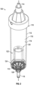
- a drip chamber insert includes an elongate body portion having an upper surface, and a base portion positioned downstream of the elongate body portion for coupling to a drip chamber.
- the base portion has an upper surface and a lower surface defining an outlet orifice of the drip chamber insert.
- the drip chamber insert further includes a first chamber disposed in the elongate body portion and fluidly coupled to the upper surface via an inlet orifice and to the outlet orifice via the base portion, an anti-run-dry membrane disposed on the upper surface of the elongate body portion extending over the inlet orifice, and a second chamber disposed in the longitudinally extending body and extending from the upper surface to the base portion.
- a low flowrate orifice extends from a base of the second chamber into the base portion for fluidly coupling the second chamber with the outlet orifice.
- a drip chamber assembly includes a drip chamber including a housing having an inlet for receiving an IV fluid, an outlet for dispensing the IV fluid to a patient, and a cavity defined by an inner surface of the housing.
- a drip chamber insert is disposed in the cavity.
- the drip chamber insert includes an elongate body portion having an upper surface, and a base portion positioned downstream of the elongate body portion, the base portion. The base portion defines an outlet orifice of the drip chamber insert and may be fluidly connected to the outlet of the drip chamber.
- the drip chamber further includes a first chamber disposed in the elongate body portion, a second chamber disposed in the elongate body portion and extending from the upper surface to the base portion, and a low flowrate orifice extending from a base of the second chamber into the base portion for fluidly coupling the second chamber with the drip chamber outlet.
- the first chamber includes an inlet orifice fluidly coupling the first chamber to the upper surface of the elongate body portion, and an anti-run-dry membrane disposed on the upper surface of the elongate body portion extending over the inlet orifice.
- the inlet orifice is fluidly coupled to the drip chamber inlet for receiving the IV fluid in a first flow condition.
- the second chamber has an open proximal end for receiving at least a portion of the IV fluid in a second flow condition.
- Some gravity sets attempt to address the above issue by employing a device that utilizes the patient's blood pressure to flow out through an injection site into a container with a plunger.
- the device is used mainly for keeping the vein open during the infusion of contrast media.
- the plunger is driven back with the blood pressure and can be driven with a motor to help draw out blood if the blood pressure is not enough to drive the plunger.
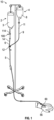
- the present description relates in general to drip chambers, and in particular to a drip chamber including a drip chamber insert capable of slowing down the flow rate of the final volume of fluid in the drip chamber towards completion of infusion to allow the patient's vein to stay open until a clinician can tend to the completed infusion.
- the drip chamber assembly may be fluidly coupled to a catheter which may be inserted into a vein of a patient for infusion of an IV fluid and/or blood draw.
- the drip chamber assembly includes a drip chamber having an additional component mounted or otherwise affixed therein.
- the additional component may be welded, glued, or otherwise similarly affixed to a base portion of the drip chamber.
- the additional component may be a drip chamber insert that is affixed (for example, but not limited to welded or glued) into the drip chamber with the capability of slowing down the flow of the final volume (for example, but not limited to the final 10-60 milliliters (ml)) of IV fluid remaining in the drip chamber after depletion of the IV fluid in the IV fluid bag.
- the slowing of the flow rate of the IV fluid at completion of the infusion advantageously allows a patient's vein to stay open longer until a clinician can tend to the completed infusion.
- the drip chamber insert splits or otherwise partitions the drip chamber into two chambers: (i) a first chamber having an inlet orifice (also referred to herein as a normal flow orifice) for normal, unrestricted flow of the IV fluid, and (ii) a second chamber with a small orifice at a bottom or base of the second chamber that allows for a greatly reduced keep-vein-open (KVO) flow rate of the IV fluid.
- a first chamber having an inlet orifice (also referred to herein as a normal flow orifice) for normal, unrestricted flow of the IV fluid
- KVO keep-vein-open
- an anti-run-dry filter or membrane may be attached to an upper surface of drip chamber insert extending over the top of the normal flow orifice to ensure that when the IV fluid in the drip chamber falls below the predetermined threshold value, the anti-run-dry membrane may restrict or otherwise block the remaining IV fluid from entering the normal fluid pathway in the first chamber. Accordingly, the remaining IV fluid in the drip chamber will flow through the path of less fluid flow resistance; the KVO fluid pathway delivers fluid to the patient at the greatly reduced flowrate via the low flowrate orifice.
- the normal fluid pathway delivers the fluid at a flow rate ranging from about 50 milliliters/hour (ml/hr) to about 1000 ml/hr, in some instances ranging from about 200 ml/hr to 800 ml/hr, more typically from about 400 ml/hr to 600 ml/hr, and in some embodiments approximately 500 ml/hr.
- ml/hr milliliters/hour
- the KVO fluid pathway delivers the fluid at a reduced flow rate ranging from about 2 ml/hr to about 10 ml/hr, in some instances ranging from about 3 ml/hr to 9 ml/hr, more typically from about 5 ml/hr to 7 ml/hr, and in some embodiments approximately 6 ml/hr. Accordingly, towards completion of infusion, the IV fluid is dispensed to the patient via the low flowrate orifice to allow the patient's vein to stay open until a clinician can tend to the completed infusion.
- the KVO fluid pathway may deliver the fluid at a slower or reduced rate in the range of about 1% to 15% of the flow rate through the normal fluid pathway, in some instances in the range of about 2% to 10% of the flow rate through the normal fluid pathway, more typically from about 3% to 5% of the flow rate through the normal fluid pathway, and in some embodiments approximately 4% of the flow rate through the normal fluid pathway.
- a slower or reduced rate in the range of about 1% to 15% of the flow rate through the normal fluid pathway, in some instances in the range of about 2% to 10% of the flow rate through the normal fluid pathway, more typically from about 3% to 5% of the flow rate through the normal fluid pathway, and in some embodiments approximately 4% of the flow rate through the normal fluid pathway.
Landscapes
- Health & Medical Sciences (AREA)
- Vascular Medicine (AREA)
- Engineering & Computer Science (AREA)
- Anesthesiology (AREA)
- Biomedical Technology (AREA)
- Heart & Thoracic Surgery (AREA)
- Hematology (AREA)
- Life Sciences & Earth Sciences (AREA)
- Animal Behavior & Ethology (AREA)
- General Health & Medical Sciences (AREA)
- Public Health (AREA)
- Veterinary Medicine (AREA)
- Physics & Mathematics (AREA)
- Fluid Mechanics (AREA)
- Infusion, Injection, And Reservoir Apparatuses (AREA)
Claims (15)
- Ein Tropfkammereinsatz (120), umfassend:einen länglichen Körperabschnitt (122) mit einer oberen Fläche (126) und einem stromabwärts des länglichen Körperabschnitts angeordneten Basisabschnitt (124) zur Verbindung mit einer Tropfkammer, wobei der Basisabschnitt (124) eine obere Fläche (125) und eine untere Fläche (127) aufweist, die eine Auslassöffnung (128) des Tropfkammereinsatzes definiert;eine erste Kammer (130), die in dem länglichen Körperabschnitt (122) angeordnet ist und über eine Einlassöffnung (132) mit der oberen Fläche (126) des länglichen Körperabschnitts und über den Basisabschnitt (124) mit der Auslassöffnung (128) fluidmäßig verbunden ist;eine Anti-Trockenlauf-Membran (134), die auf der oberen Fläche (126) des länglichen Körperabschnitts angeordnet ist, sich über die Einlassöffnung (132) erstreckt und so konfiguriert ist, dass sie eine Flüssigkeit hindurchlässt;eine zweite Kammer (140), die in dem länglichen Körperabschnitt (122) angeordnet ist und sich durch die obere Fläche (126) des länglichen Körperabschnitts zu dem Basisabschnitt (124) erstreckt, wobei die zweite Kammer (140) ein offenes proximales Ende (144) aufweist, das so konfiguriert ist, dass es zumindest einen Teil der Flüssigkeit in die zweite Kammer (140) aufnimmt; undeine Öffnung (150) mit niedrigem Durchfluss, die sich von einer Basis der zweiten Kammer in den Basisabschnitt (124) erstreckt, um die zweite Kammer (140) mit der Auslassöffnung (128) fluidisch zu verbinden.
- Der Tropfkammereinsatz nach Anspruch 1, wobei der längliche Körperabschnitt (122) ferner eine Seitenwand (123), die sich in Längsrichtung zwischen der oberen Fläche (126) des länglichen Körperabschnitts und dem Basisabschnitt (124) erstreckt, und eine Fluid-Bypass-Öffnung (129) umfasst, die in der Seitenwand angeordnet ist, wobei die Fluid-Bypass-Öffnung über die Öffnung (150) mit niedrigem Durchfluss mit der Auslassöffnung (128) in Fluidverbindung steht.
- Der Tropfkammereinsatz nach Anspruch 2, wobei die Öffnung (150) mit niedrigem Durchfluss eine konische Form aufweist, die sich in distaler Richtung in den Basisabschnitt (124) verjüngt.
- Der Tropfkammereinsatz nach Anspruch 2, wobei die Einlassöffnung (132), die erste Kammer (130) und die Auslassöffnung (128) strömungstechnisch gekoppelt sind, um einen ersten Fluidweg zu definieren, und in einem ersten Strömungszustand, in dem das Fluid in der Tropfkammer über einem vorbestimmten Pegel liegt, das von einer Fluidquelle in die Tropfkammer strömende Fluid durch die Anti-Trockenlauf-Membran (134) hindurchgeht und über die Einlassöffnung (132) in die erste Kammer (130) eintritt und über die Auslassöffnung (128) aus dem Tropfkammereinsatz austritt.
- Der Tropfkammereinsatz nach Anspruch 4, wobei die Anti-Trockenlauf-Membran in einer vorbestimmten Höhe über dem Basisteil angeordnet ist und der vorbestimmte Pegel des Fluids in der Tropfkammer gleich der vorbestimmten Höhe ist.
- Der Tropfkammereinsatz nach Anspruch 4, wobei die Anti-Trockenlauf-Membran (134) ein hydrophiles Material mit einer Vielzahl von Poren umfasst, durch die das Fluid strömt.
- Der Tropfkammereinsatz nach Anspruch 6, wobei das offene proximale Ende (144) der zweiten Kammer (140), die Öffnung (150) mit niedrigem Durchfluss und die Auslassöffnung (128) in Fluidverbindung stehen, um einen zweiten Fluidweg zu definieren.
- Der Tropfkammereinsatz nach Anspruch 7, wobei ein dritter Fluidweg in Längsrichtung zwischen der Seitenwand (123) des länglichen Körperteils und einer Innenfläche der Tropfkammer, durch die Fluidumgehungsöffnung (129) und in die Auslassöffnung (128) über die Öffnung (150) mit niedrigem Durchfluss definiert ist.
- Der Tropfkammereinsatz nach Anspruch 8, wobei ein vierter Fluidweg (i) in Längsrichtung zwischen der Seitenwand (123) des länglichen Körperabschnitts und der Innenfläche der Tropfkammer, (ii) in Umfangsrichtung entlang einer oberen Fläche (125) des Basisabschnitts zwischen der Seitenwand (123) des länglichen Körperabschnitts und der Innenfläche der Tropfkammer, (iii) durch die Fluidumgehungsöffnung (129) und (iv) in die Auslassöffnung (128) über die Öffnung (150) mit niedrigem Durchfluss definiert ist.
- Der Tropfkammereinsatz nach Anspruch 9, wobei die zweiten, dritten und vierten Fluidwege eine Rate begrenzen, mit der Fluid den Tropfkammereinsatz (120) verlässt, und die Anti-Trockenlauf-Membran (134) in einem zweiten Strömungszustand, wenn Fluid in der Tropfkammer unter den vorbestimmten Pegel fällt, eine Fluidsäule in der ersten Kammer (130) stützt, um zu verhindern, dass IV-Fluid in der Tropfkammer in die Einlassöffnung (132) eintritt, so dass das Fluid durch die zweiten, dritten und vierten Fluidwege fließt.
- Der Tropfkammereinsatz nach Anspruch 10, wobei der vorbestimmte Pegel, unter den das Fluid in der Tropfkammer im zweiten Strömungszustand fällt, weniger als oder gleich 60 Milliliter beträgt.
- Eine Tropfkammeranordnung (100), umfassend:eine Tropfkammer (110), die ein Gehäuse (112) mit einem Einlass (114) zur Aufnahme eines IV-Fluids, einen Auslass (116) zur Abgabe des IV-Fluids an einen Patienten und einen durch eine Innenfläche (119) des Gehäuses definierten Hohlraum (118) aufweist; undden Tropfkammereinsatz (120) nach Anspruch 1, der in dem Hohlraum so angeordnet ist, dass die Auslassöffnung (128) des Tropfkammereinsatzes stömungstechnisch mit dem Auslass (116) der Tropfkammer verbunden ist, wobei die Einlassöffnung (132) stömungstechnisch mit dem Tropfkammereinlass (114) zur Aufnahme des IV-Fluids in einem ersten Strömungszustand verbunden ist, das offene proximale Ende (144) der zweiten Kammer zumindest einen Teil des IV-Fluids in einem zweiten Strömungszustand aufnehmen kann, und die Öffnung (150) mit niedriger Strömungsrate die zweite Kammer (140) mit dem Auslass (116) der Tropfkammer fluidisch verbindet.
- Die Tropfkammeranordnung nach Anspruch 12, wobei die Einlassöffnung (132) axial mit dem Einlass (114) der Tropfkammer ausgerichtet ist.
- Die Tropfkammeranordnung nach Anspruch 12, wobei der Tropfkammereinlass (114), die Einlassöffnung (132), die erste Kammer (130), die Auslassöffnung (128) und der Auslass (116) der Tropfkammer fluidisch gekoppelt sind, um einen ersten Fluidweg zu definieren, und in dem ersten Strömungszustand, in dem das IV-Fluid in der Tropfkammer über einem vorbestimmten Pegel liegt, das in die Tropfkammer fließende IV-Fluid die Anti-Trockenlauf-Membran (134) passiert und in die erste Kammer (130) über die Einlassöffnung (132) eintritt.
- Die Tropfkammeranordnung nach Anspruch 14, wobei die Anti-Trockenlauf-Membran (134) ein poröses hydrophiles Material umfasst.
Priority Applications (1)
| Application Number | Priority Date | Filing Date | Title |
|---|---|---|---|
| EP25176738.0A EP4578474A3 (de) | 2021-06-07 | 2022-05-18 | Tropfkammereinsatz zur automatischen reduzierung der flüssigkeitsflussrate bei der infusionsausführung zur offenhaltung der vene |
Applications Claiming Priority (2)
| Application Number | Priority Date | Filing Date | Title |
|---|---|---|---|
| US17/341,070 US12208233B2 (en) | 2021-06-07 | 2021-06-07 | Drip chamber insert for automatically reducing fluid flow rate at infusion completion to keep vein open |
| PCT/US2022/029921 WO2022260837A1 (en) | 2021-06-07 | 2022-05-18 | Drip chamber insert for automatically reducing fluid flow rate at infusion completion to keep vein open |
Related Child Applications (2)
| Application Number | Title | Priority Date | Filing Date |
|---|---|---|---|
| EP25176738.0A Division-Into EP4578474A3 (de) | 2021-06-07 | 2022-05-18 | Tropfkammereinsatz zur automatischen reduzierung der flüssigkeitsflussrate bei der infusionsausführung zur offenhaltung der vene |
| EP25176738.0A Division EP4578474A3 (de) | 2021-06-07 | 2022-05-18 | Tropfkammereinsatz zur automatischen reduzierung der flüssigkeitsflussrate bei der infusionsausführung zur offenhaltung der vene |
Publications (3)
| Publication Number | Publication Date |
|---|---|
| EP4351677A1 EP4351677A1 (de) | 2024-04-17 |
| EP4351677B1 true EP4351677B1 (de) | 2025-07-09 |
| EP4351677C0 EP4351677C0 (de) | 2025-07-09 |
Family
ID=82258296
Family Applications (2)
| Application Number | Title | Priority Date | Filing Date |
|---|---|---|---|
| EP22734397.7A Active EP4351677B1 (de) | 2021-06-07 | 2022-05-18 | Tropfkammereinsatz zur automatischen reduzierung der flüssigkeitsflussrate bei der infusionsausführung zur offenhaltung der vene |
| EP25176738.0A Pending EP4578474A3 (de) | 2021-06-07 | 2022-05-18 | Tropfkammereinsatz zur automatischen reduzierung der flüssigkeitsflussrate bei der infusionsausführung zur offenhaltung der vene |
Family Applications After (1)
| Application Number | Title | Priority Date | Filing Date |
|---|---|---|---|
| EP25176738.0A Pending EP4578474A3 (de) | 2021-06-07 | 2022-05-18 | Tropfkammereinsatz zur automatischen reduzierung der flüssigkeitsflussrate bei der infusionsausführung zur offenhaltung der vene |
Country Status (8)
| Country | Link |
|---|---|
| US (2) | US12208233B2 (de) |
| EP (2) | EP4351677B1 (de) |
| JP (1) | JP2024522460A (de) |
| CN (2) | CN115501414A (de) |
| AU (1) | AU2022291108A1 (de) |
| CA (1) | CA3218859A1 (de) |
| MX (1) | MX2023013275A (de) |
| WO (1) | WO2022260837A1 (de) |
Families Citing this family (1)
| Publication number | Priority date | Publication date | Assignee | Title |
|---|---|---|---|---|
| CN118381954A (zh) | 2019-05-15 | 2024-07-23 | 谷歌有限责任公司 | 定制的补充媒体内容的动态整合 |
Family Cites Families (4)
| Publication number | Priority date | Publication date | Assignee | Title |
|---|---|---|---|---|
| US4173222A (en) | 1976-08-19 | 1979-11-06 | Abbott Laboratories | Apparatus for controllably administering a parenteral fluid |
| US5188603A (en) | 1991-01-03 | 1993-02-23 | Vaillancourt Vincent L | Fluid infusion delivery system |
| US7491191B2 (en) | 2004-02-13 | 2009-02-17 | Liebel-Flarsheim Company | Keep vein open method and injector with keep vein open function |
| GB2584875B (en) | 2019-06-18 | 2021-09-15 | Charles Devlin West Jonathan | Flow metering insert and/or device |
-
2021
- 2021-06-07 US US17/341,070 patent/US12208233B2/en active Active
-
2022
- 2022-05-18 CA CA3218859A patent/CA3218859A1/en active Pending
- 2022-05-18 EP EP22734397.7A patent/EP4351677B1/de active Active
- 2022-05-18 MX MX2023013275A patent/MX2023013275A/es unknown
- 2022-05-18 EP EP25176738.0A patent/EP4578474A3/de active Pending
- 2022-05-18 AU AU2022291108A patent/AU2022291108A1/en active Pending
- 2022-05-18 JP JP2023571262A patent/JP2024522460A/ja active Pending
- 2022-05-18 WO PCT/US2022/029921 patent/WO2022260837A1/en not_active Ceased
- 2022-06-07 CN CN202210638973.2A patent/CN115501414A/zh active Pending
- 2022-06-07 CN CN202221409546.9U patent/CN219271753U/zh active Active
-
2024
- 2024-12-17 US US18/983,882 patent/US20250114515A1/en active Pending
Also Published As
| Publication number | Publication date |
|---|---|
| CN115501414A (zh) | 2022-12-23 |
| JP2024522460A (ja) | 2024-06-21 |
| EP4351677A1 (de) | 2024-04-17 |
| US20220387707A1 (en) | 2022-12-08 |
| US12208233B2 (en) | 2025-01-28 |
| MX2023013275A (es) | 2023-11-30 |
| EP4351677C0 (de) | 2025-07-09 |
| EP4578474A2 (de) | 2025-07-02 |
| CA3218859A1 (en) | 2022-12-15 |
| EP4578474A3 (de) | 2025-09-24 |
| WO2022260837A1 (en) | 2022-12-15 |
| US20250114515A1 (en) | 2025-04-10 |
| AU2022291108A1 (en) | 2023-11-23 |
| CN219271753U (zh) | 2023-06-30 |
Similar Documents
| Publication | Publication Date | Title |
|---|---|---|
| US5188603A (en) | Fluid infusion delivery system | |
| AU628054B2 (en) | Implantable infusion apparatus | |
| US5290238A (en) | Self priming tubing set for an infusion device | |
| CA2974966C (en) | Air stop membrane for maintaining a fluid column in an iv set | |
| US20160213862A1 (en) | Iv set having an air stop membrane | |
| JPH04246370A (ja) | 心臓血管組立体 | |
| US20250114515A1 (en) | Drip chamber insert for automatically reducing fluid flow rate at infusion completion to keep vein open | |
| US20220409813A1 (en) | Pressure-regulating connector for infusion | |
| EP4237035B1 (de) | Konvergent-divergente tropfkammer mit integriertem schwimmenden ventilkörper | |
| DK202370050A1 (en) | A flushing apparatus for use with an iv infusion set and an iv infusion set having an automatic flushing function | |
| EP1960019B1 (de) | Durchflusskontrollanordnung mit einem Ventil und einem Durchflussregler | |
| WO2022020508A1 (en) | Floater based flow control device for gravity iv sets | |
| US20240123211A1 (en) | Universal fluid connector assembly with a regulating valve component |
Legal Events
| Date | Code | Title | Description |
|---|---|---|---|
| STAA | Information on the status of an ep patent application or granted ep patent |
Free format text: STATUS: UNKNOWN |
|
| STAA | Information on the status of an ep patent application or granted ep patent |
Free format text: STATUS: THE INTERNATIONAL PUBLICATION HAS BEEN MADE |
|
| PUAI | Public reference made under article 153(3) epc to a published international application that has entered the european phase |
Free format text: ORIGINAL CODE: 0009012 |
|
| STAA | Information on the status of an ep patent application or granted ep patent |
Free format text: STATUS: REQUEST FOR EXAMINATION WAS MADE |
|
| 17P | Request for examination filed |
Effective date: 20240108 |
|
| AK | Designated contracting states |
Kind code of ref document: A1 Designated state(s): AL AT BE BG CH CY CZ DE DK EE ES FI FR GB GR HR HU IE IS IT LI LT LU LV MC MK MT NL NO PL PT RO RS SE SI SK SM TR |
|
| DAV | Request for validation of the european patent (deleted) | ||
| DAX | Request for extension of the european patent (deleted) | ||
| GRAP | Despatch of communication of intention to grant a patent |
Free format text: ORIGINAL CODE: EPIDOSNIGR1 |
|
| STAA | Information on the status of an ep patent application or granted ep patent |
Free format text: STATUS: GRANT OF PATENT IS INTENDED |
|
| INTG | Intention to grant announced |
Effective date: 20250207 |
|
| GRAS | Grant fee paid |
Free format text: ORIGINAL CODE: EPIDOSNIGR3 |
|
| GRAA | (expected) grant |
Free format text: ORIGINAL CODE: 0009210 |
|
| STAA | Information on the status of an ep patent application or granted ep patent |
Free format text: STATUS: THE PATENT HAS BEEN GRANTED |
|
| AK | Designated contracting states |
Kind code of ref document: B1 Designated state(s): AL AT BE BG CH CY CZ DE DK EE ES FI FR GB GR HR HU IE IS IT LI LT LU LV MC MK MT NL NO PL PT RO RS SE SI SK SM TR |
|
| REG | Reference to a national code |
Ref country code: GB Ref legal event code: FG4D |
|
| REG | Reference to a national code |
Ref country code: CH Ref legal event code: EP |
|
| REG | Reference to a national code |
Ref country code: IE Ref legal event code: FG4D |
|
| U01 | Request for unitary effect filed |
Effective date: 20250709 |
|
| U07 | Unitary effect registered |
Designated state(s): AT BE BG DE DK EE FI FR IT LT LU LV MT NL PT RO SE SI Effective date: 20250715 |
|
| PG25 | Lapsed in a contracting state [announced via postgrant information from national office to epo] |
Ref country code: IS Free format text: LAPSE BECAUSE OF FAILURE TO SUBMIT A TRANSLATION OF THE DESCRIPTION OR TO PAY THE FEE WITHIN THE PRESCRIBED TIME-LIMIT Effective date: 20251109 |
|
| PG25 | Lapsed in a contracting state [announced via postgrant information from national office to epo] |
Ref country code: NO Free format text: LAPSE BECAUSE OF FAILURE TO SUBMIT A TRANSLATION OF THE DESCRIPTION OR TO PAY THE FEE WITHIN THE PRESCRIBED TIME-LIMIT Effective date: 20251009 |
|
| PG25 | Lapsed in a contracting state [announced via postgrant information from national office to epo] |
Ref country code: HR Free format text: LAPSE BECAUSE OF FAILURE TO SUBMIT A TRANSLATION OF THE DESCRIPTION OR TO PAY THE FEE WITHIN THE PRESCRIBED TIME-LIMIT Effective date: 20250709 |
|
| PG25 | Lapsed in a contracting state [announced via postgrant information from national office to epo] |
Ref country code: GR Free format text: LAPSE BECAUSE OF FAILURE TO SUBMIT A TRANSLATION OF THE DESCRIPTION OR TO PAY THE FEE WITHIN THE PRESCRIBED TIME-LIMIT Effective date: 20251010 |
|
| PG25 | Lapsed in a contracting state [announced via postgrant information from national office to epo] |
Ref country code: PL Free format text: LAPSE BECAUSE OF FAILURE TO SUBMIT A TRANSLATION OF THE DESCRIPTION OR TO PAY THE FEE WITHIN THE PRESCRIBED TIME-LIMIT Effective date: 20250709 |
|
| PG25 | Lapsed in a contracting state [announced via postgrant information from national office to epo] |
Ref country code: RS Free format text: LAPSE BECAUSE OF FAILURE TO SUBMIT A TRANSLATION OF THE DESCRIPTION OR TO PAY THE FEE WITHIN THE PRESCRIBED TIME-LIMIT Effective date: 20251009 |
|
| PG25 | Lapsed in a contracting state [announced via postgrant information from national office to epo] |
Ref country code: ES Free format text: LAPSE BECAUSE OF FAILURE TO SUBMIT A TRANSLATION OF THE DESCRIPTION OR TO PAY THE FEE WITHIN THE PRESCRIBED TIME-LIMIT Effective date: 20250709 |
|
| PG25 | Lapsed in a contracting state [announced via postgrant information from national office to epo] |
Ref country code: SM Free format text: LAPSE BECAUSE OF FAILURE TO SUBMIT A TRANSLATION OF THE DESCRIPTION OR TO PAY THE FEE WITHIN THE PRESCRIBED TIME-LIMIT Effective date: 20250709 |
|
| PG25 | Lapsed in a contracting state [announced via postgrant information from national office to epo] |
Ref country code: CZ Free format text: LAPSE BECAUSE OF FAILURE TO SUBMIT A TRANSLATION OF THE DESCRIPTION OR TO PAY THE FEE WITHIN THE PRESCRIBED TIME-LIMIT Effective date: 20250709 |
|
| PG25 | Lapsed in a contracting state [announced via postgrant information from national office to epo] |
Ref country code: SK Free format text: LAPSE BECAUSE OF FAILURE TO SUBMIT A TRANSLATION OF THE DESCRIPTION OR TO PAY THE FEE WITHIN THE PRESCRIBED TIME-LIMIT Effective date: 20250709 |